Charge Portlink
Last updated: October 10, 2024
Overviewlink
The charge port assembly is made up of 4 components:
- Charge port inlet with latch and high-voltage busbars with Ancillary Bay connector
- Charge port door
- Trim piece with Printed Circuit Board (PCB), status LED indicators (located behind the door), and vanity LED (illuminating the inlet from the top)
- Charge port Electronic Control Unit (ECU)
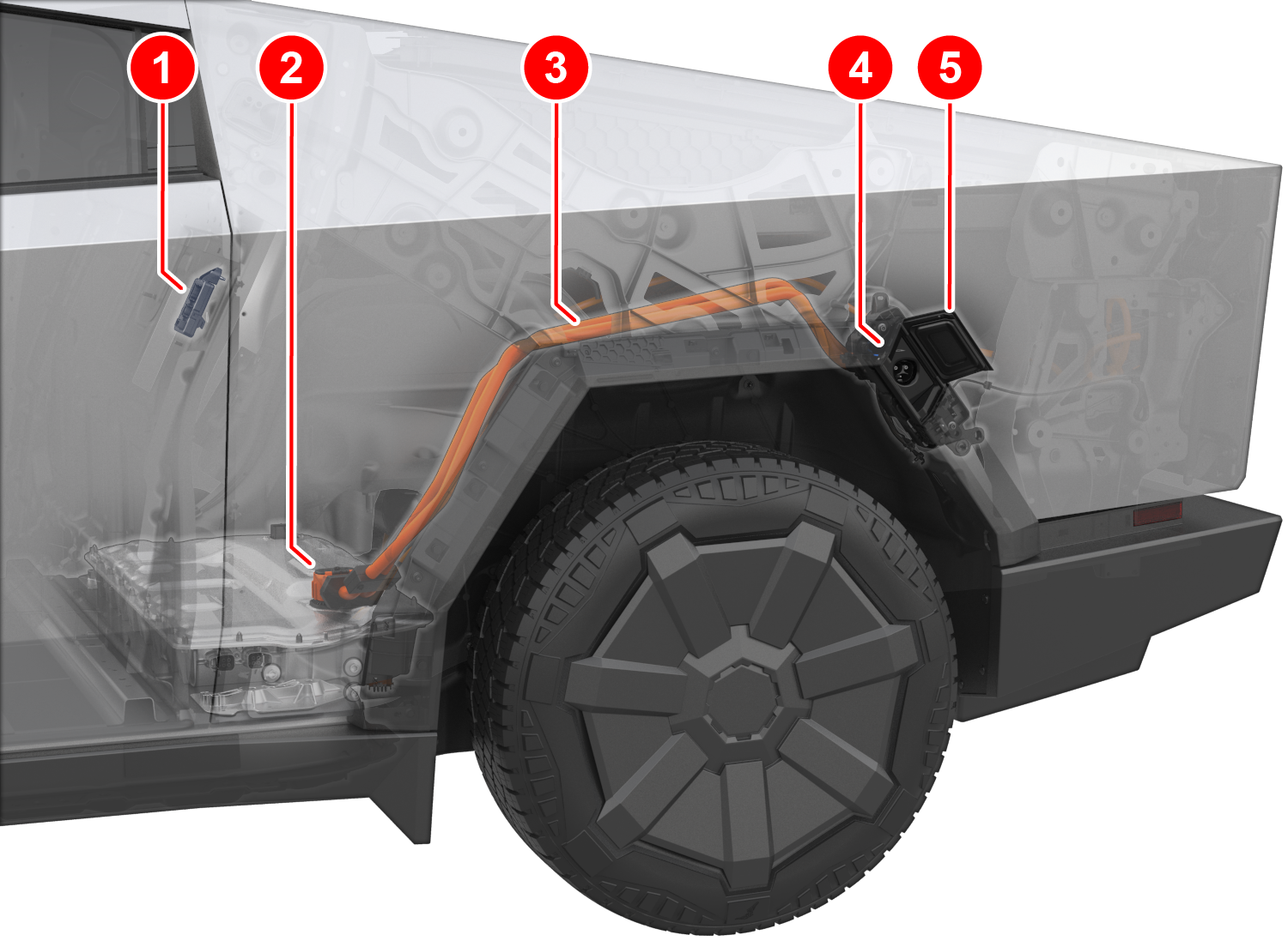
The charge port is located inside the left-hand wheel arch garnish, which hides the charge inlet when the charge port door is closed.
 |
|---|
| 1. Charge port ECU 2. Charge port Ancillary Bay connector 3. HV busbars 4. Charge port inlet assembly 5. Charge port door |
| Charge Port Overview |
The charge port door is motorized and opens in a 45º angle. The charge port ECU is located in an enclosure separate from the charge port inlet inside the Cybertruck cabin at the back wall behind the rear-left seat cushion. The charge port ECU has vehicle communication with external charge equipment such as Supercharger, Wall Connector, and Mobile Connector. It also has additional pinouts for inlet heating. The charge port ECU is connected to the High Voltage System (HVS) Controller Area Network (CAN) bus. This means it can communicate with the Battery Management System (BMS), the Power Conversion System (PCS), and the High Voltage Controller (HVC). The HV charge port busbars connect to a connector on top of the HV battery enclosure in the left rear corner from where power is distributed via the fast-charge link to the fast-charge contactors at the rear of the HV battery for Direct Current (DC) charging. The fast charge link is further connected via an HV harness inside the battery to the AC Junction Box (ACJB) at the rear of the battery in order to connect the charge port to the Alternating Current (AC) side of the PCS for AC charging.
 |
|---|
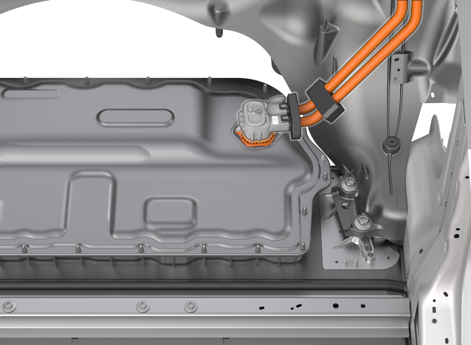
| Charge Port Connector At HV Battery |
The HV busbars are one assembly with the charge port inlet and connect to the ancillary bay using bolted connections. The charge handle should be 5-10in (15-25 cm) from the charge port door for effective operation of the remote "Open" button. The charge port inlet around the inlet pins can be heated.
Charge Port Assembly and Operationlink
 |
|---|
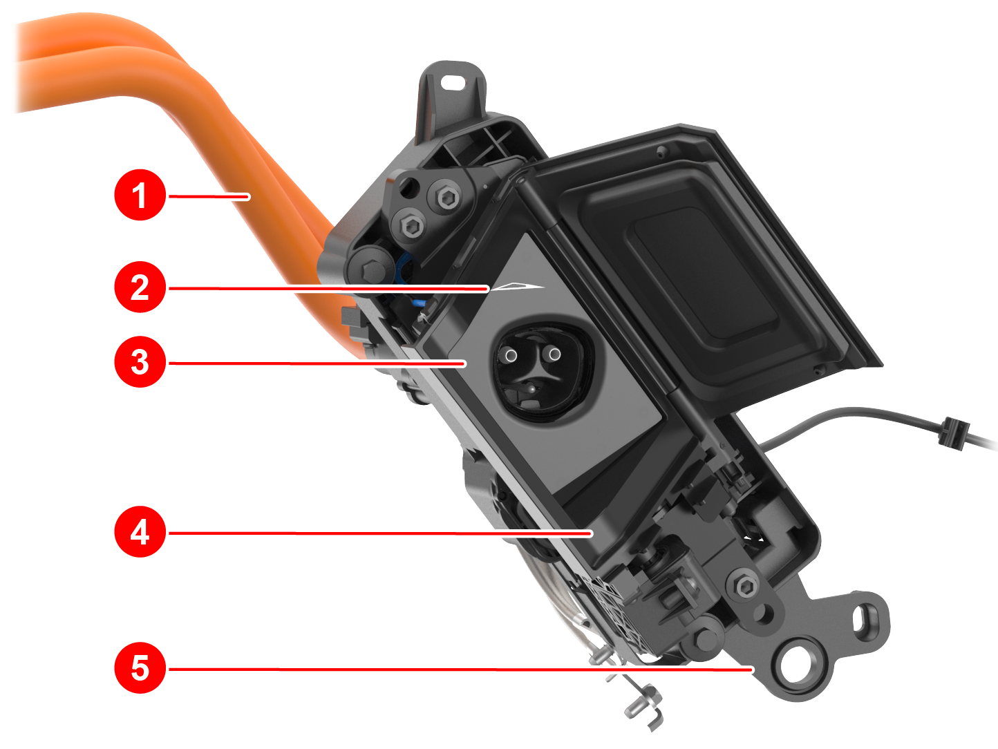
| 1. HV busbars 2. Trim with status LED 3. Inlet trim 4. Inlet assembly 5. Carrier mounting points |
| Charge Port Overview Front |
 |
|---|
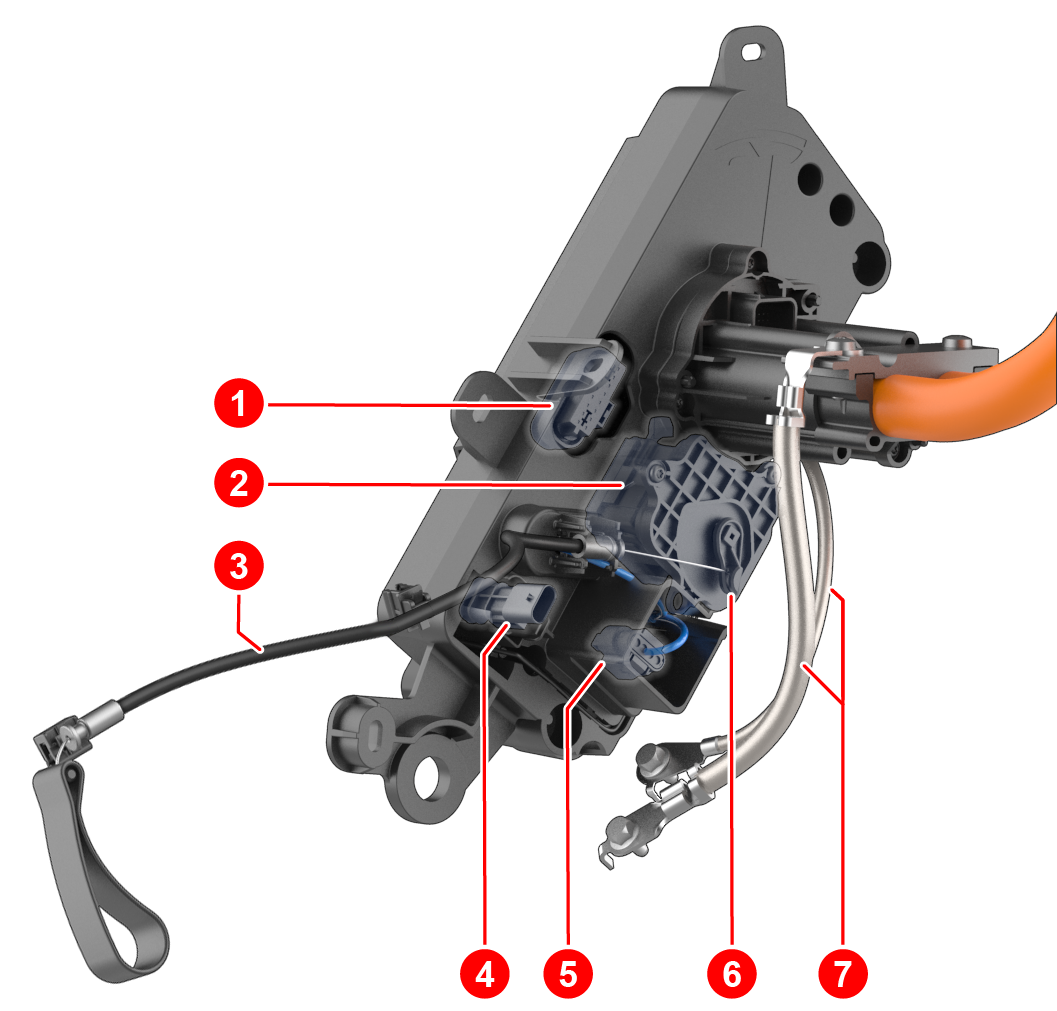
| 1. Charge port LV connector 2. Latch actuator 3. Manual release cable 4. Charge port door LV connector 5. Latch actuator LV connector 6. Latch actuator manual release arm 7. Inlet ground straps |
| Charge Port Overview Rear |
On single-phase charge ports, the charge port HV busbars are used for AC charging (up to 48A limited by PCS) and DC charging.
The HV battery connector no longer has a High Voltage Interlock Loop (HVIL) or Charge Port Interlock Loop (CPIL). Inside the connector, the busbars are mounted to the HV battery using bolted connections. The bolts can be accessed through a lid on top of the connector.
The inlet vanity LED at the top of the charge port inlet helps users see the inlet easier in the dark. The inlet vanity LED is illuminated when the charge port door is open, the vehicle is not asleep, and a charge cable is not plugged into the vehicle.
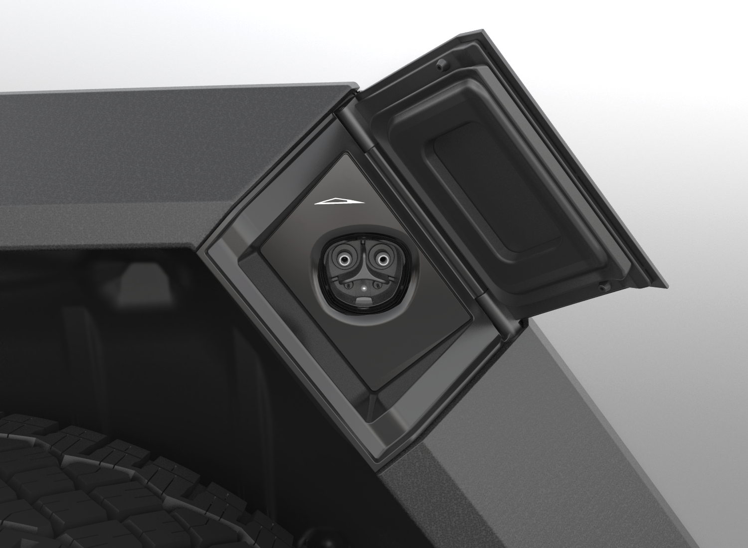 |
|---|
| Charge Port Inlet (Door Open) With Status LED |
The status LEDs illuminate a Cybertruck logo on the upper left side of the cosmetic trim piece.
The flash speed pattern of the status LEDs is inversely related to the State Of Charge (SOC). When the SOC is closer to 100% SOC, the flashing is slower, and when the vehicle is done charging, the charge port displays constant green. The flash speed is not related to the line current value or the charge limit setting.
The charge port status LED is active when the charge port door is open and one of the following is true:
- Truck is unlocked.
- Two-minute LED timer is running.
- Charge port latch is disengaged.
If none of those combinations are met, then the LED will be off. Each LED color then has its own conditions that need to be met as described in the table below:
| Status LED | LED Color | Charge Port State | Set Conditions |
|---|---|---|---|
 |
Solid White | Charging cable can be removed or inserted. | The charge port latch is disengaged. |
 |
Solid Amber | Cable is inserted, but not properly latched. | The cable is connected, charge port latch is not engaged, vehicle is trying to engage latch, and vehicle is not charging. |
 |
Solid Red | Either the charger, charge port, or Electric Vehicle Supply Equipment (EVSE) is not operating as expected. | One of the following:
|
 |
Flashing Green | Charging at expected current. | Cable is connected, charge port latch is engaged, and vehicle is actively charging. |
 |
Flashing Amber | Charging at reduced current. | Cable is connected, charge port latch is disengaged, and vehicle is actively charging. |
 |
Solid Green | Charging is complete. | Cable is connected and vehicle is no longer charging. |
 |
Solid Blue | Pilot is present. | Cable is connected and either a pilot signal or fast charger is present. |
The rear left Bluetooth Low-Energy (BLE) endpoint hosts the Ultra High Frequency (UHF) antenna and transceiver. Once it detects Radio Frequency (RF) signals from a charge handle, it sends the request to the security controller (VCSEC), which then forwards the charge port door request to open via CAN to the charge port ECU. Charge port door position and presence are detected via two separate Hall effect sensors: one mounted next to the door hinge to sense door opening positions and the other mounted in the cosmetic trim piece to sense whether the door is present when closed. The hall sensor mounted in the cosmetic trim piece is also used to determine whether the user pushes the door to open it. For this, the charge port ECU relies on relative changes to the Hall effect sensor reading. Since Hall effect sensors measure the strength of a magnetic field, one magnet is mounted to the door hinge, while another is molded into the door.
Two Low Voltage (LV) harnesses connect the charge port ECU to the charge port:
- One connects to the inner puck for proximity, pilot, inlet heating, and temperature measurements.
- The other one connects to the latch for actuation and position sensing.
Since the busbars are fixed to the charge port inlet, the charge port is no longer equipped with a back cover, thus there is also no back cover sensing.
Charge Port ECUlink
The charge port ECU controls the following sub-components:
- Charge port door motor
- Charge port door position Hall effect sensor
- Charge port door presence Hall effect sensor
- Charge port latch
- Charge port latch switch
- LEDs
- Inlet thermistors
- Charge port heater
- Bed outlets door position Hall effect sensor
The charge port ECU connects to external charge equipment through control pilot and proximity pins in the charge inlet. The charge port ECU is not connected to HV power. The charge port ECU enclosure is similar across multiple regions and can house different internal hardware, resulting in different connector pinout. Therefore, in some cases it may be necessary to verify that the charge port ECU unit matches the vehicle it is being installed in.
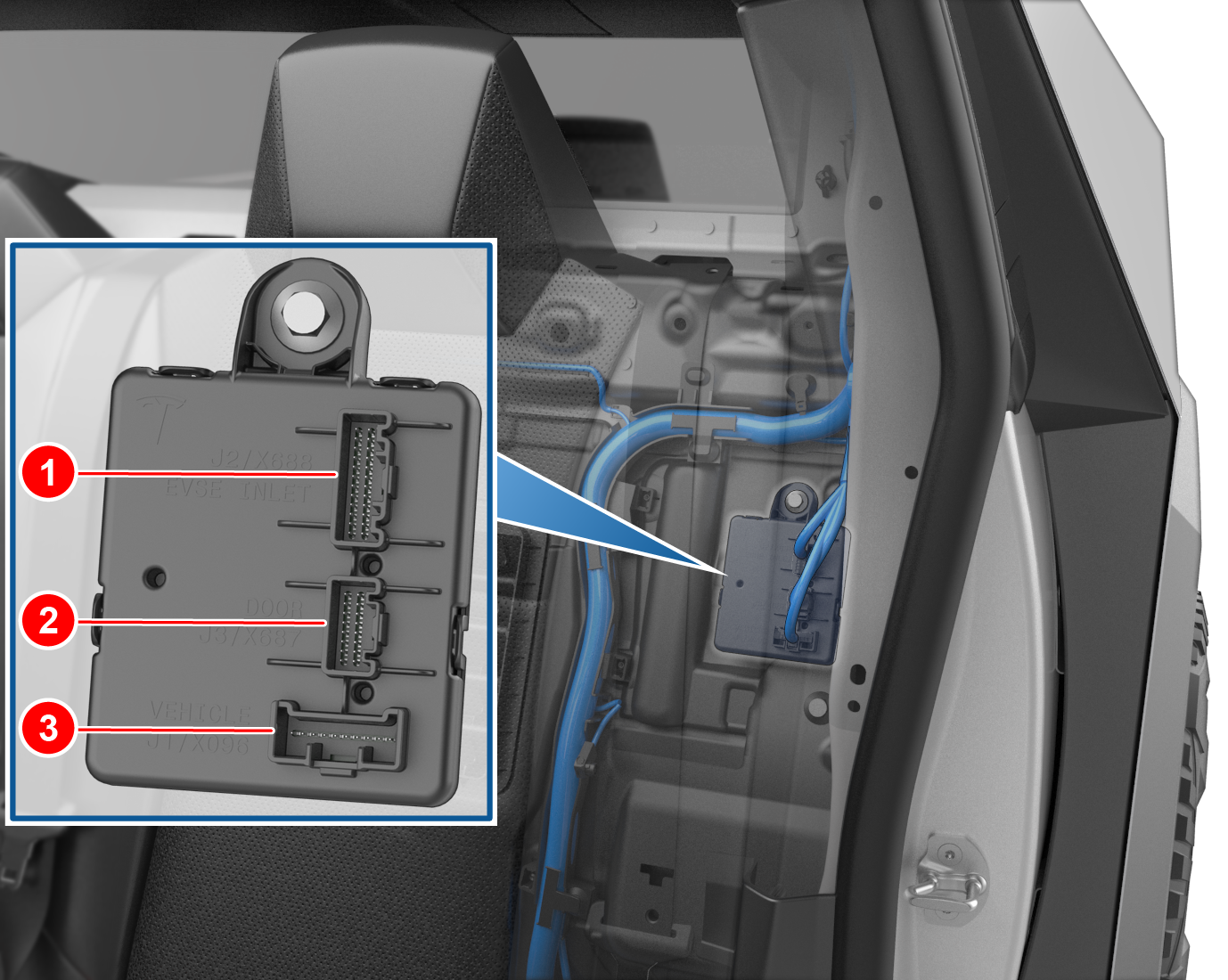 |
|---|
| 1. Inlet connector 2. Bed outlet door connector 3. Vehicle connector |
| Charge Port ECU Location Inside Cabin |
The pins within the 24-pin plug connector for the inlet LV harness connects circuits for the following features: proximity, pilot, thermistors, latch drive, latch sense, and inlet heater. The pins within the 16-pin plug connector for the trim LV harness connects circuits for the following features: LEDs, door sense, and door drive.
A 5V source connected to a 330 Ω resistor supplies the proximity pin. This allows detecting the presence of a charge handle, and the button press state on the handle. In the unlikely event that the cable state is unknown to the vehicle controllers (left controller / right controller) and drive inverter (for instance because the charge port ECU is missing on CAN), the customer can manually override and confirm on the touchscreen that there is indeed no charge cable connected before the vehicle allows them to shift into Drive.
The pilot pin detects the duty cycle of a 1 kHz pulse width modulation (PWM) signal sent from external charge equipment. The duty cycle indicates the maximum allowable current draw from the charging station. The positive amplitude of the pilot signal indicates vehicle readiness for charging (see Gen 2 UMC Theory of Operation for more details). Additionally, the charge port ECU controls Single Wire Controller Area Network (SWCAN) communication, which means the charge port ECU has the SWCAN relay and transceiver to communicate with external charging products manufactured by Tesla, such as Supercharger. The charge port sends relevant CAN messages from the SWCAN bus to the HVS bus where the BMS, PCS, and HVC are connected. Furthermore, the charge port ECU is equipped with a Powerline Communication (PLC) modem to support Combined Charging System (CCS) communication.
The charge port ECU connects to the HVC with two hardware lines:
- The charge port fault line
- Bidirectional active-low signal used by HVC to disallow charging and door opening.
-
This signal is used to prevent HV exposure when, for instance, the fast-charge contactors are welded or assumed welded. The signal can also be set low by the charge port when there are risks of HV exposure. The fault line immediately stops charging (via hardware and software) if charging is active.
-
The charge port latch enable line
- Unidirectional active high signal used by HVC to allow the charge port to drive the latch into disengaged state for cable insertion.
- The charge port cannot drive the latch into disengaged position if this signal is not active.
Since there is thermal sensing of the charge port inlet power pins, the charge port ECU can read temperatures while charging, which allows the vehicle to monitor temperature changes and reduce the charge rate if needed.
Note
Always consult the circuit diagram and connector reference for the vehicle being diagnosed to confirm which connector is used.
Charge Port Doorlink
The charge port door can open three different ways:
- A request by the User Interface (UI)
- A request by the Mobile App
- Pressing the charge port door
- Pressing the button on a Tesla charge handle
- Pressing and holding the trunk key on the keyfob
When the charge handle is pressed, an RF signal is sent to the rear left BLE endpoint. The endpoint connects to VCSEC, which then sends the request via CAN to the charge port ECU. A Hall effect sensor, mounted to the door driveshaft with a magnet, senses the door position. The charge port ECU uses another Hall effect sensor in the left corner of the trim piece with a magnet molded into the charge port door to determine whether the door is in the closed/open/pressed state. Since this Hall effect sensor is located on the left corner of the charge port door, it is easiest for the Hall effect sensor to detect door press when pushing at this location. The charge port ECU measures the door motor current for accurate control during door actuation, and stall current detection when reaching fully closed/open positions.
The door motor uses a gear to produce appropriate torque for door actuation. Normally, customers should not need to manually move the door since it will automatically close 3 seconds after removing a charge handle. If customer moves the door manually when a handle is not connected, the charge port door will close.
Charge Port Inlet Latchlink
The charge port latch locks the charge handle in place when charging and current is flowing to prevent live disconnect. The charge port latch is actuated by a cam for converting rotational movement into linear movement. The picture on the left shows the latch arm mounted to the cam (without the latch cover), and the picture on the right shows just the cam with the latch arm hidden.
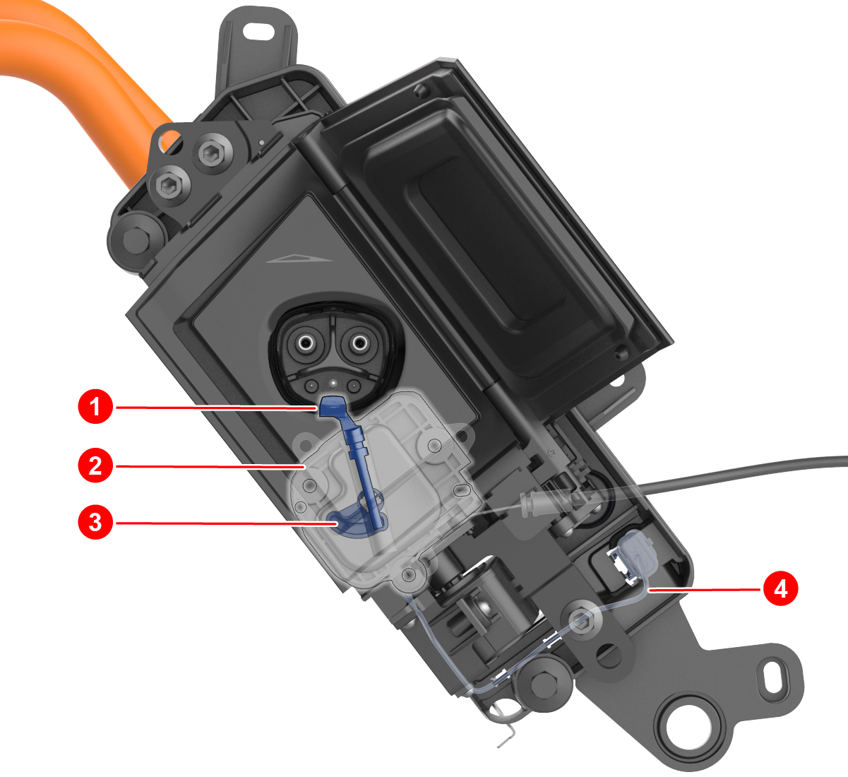 |
|---|
| 1. Latch pin 2. Latch actuator 3. Latch cam 4. Latch actuator LV connector |
| Charge Port Latch Mechanism |
The latch uses binary position sensing to report if it is engaged or disengaged. There is no continuous position sensing, which means there is no need for calibration either. The latch needs to be driven by the charge port ECU into engaged and disengaged positions, meaning there is no spring to force it into the engaged state if the latch is undriven. The charge port drives the latch at low voltage in the engaged direction every four seconds whenever the vehicle is actively charging. This is done to confirm that the latch is connected by sensing the latch motor current, since a disconnected latch looks electrically identical to an engaged latch. This can cause a quiet “ticking” noise that is noticeable when listening closely.
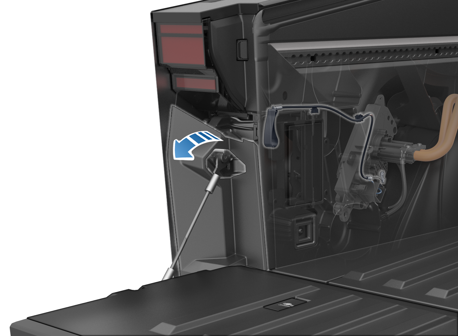
Charge Port Latch Manual Release Cablelink
The charge port latch manual release cable is used in emergency situations where the latch or LV support is malfunctioning while a charge cable is plugged in. This is the only situation the latch release cable should be used. The latch release cable should never be used to disengage the latch to force insert a charge cable. This is because if the latch does not disengage, the inlet could be live. The latch release handle is accessible by users from the left-hand tailgate area after the tailgate is opened.
 |
|---|
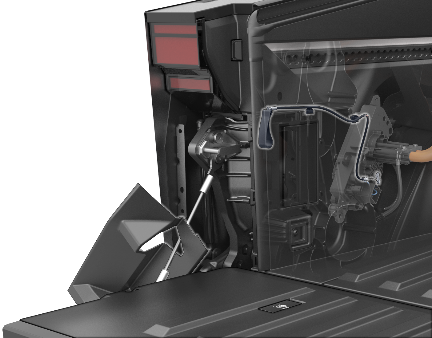 |
| Accessing The Manual Release Cable |
Serviceabilitylink
Electrical Connectionslink
To ensure low resistance connections, all busbar connections need to be established with a sufficient amount of electrical joint compound applied.
Note
Always refer to the Service Manual for the latest instructions.
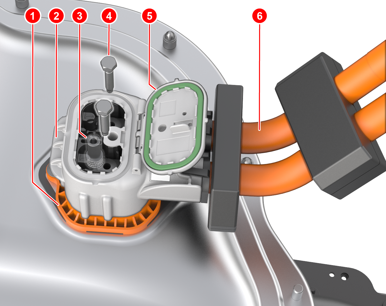 |
|---|
| 1. Ancillary Bay connector header 2. Charge port HV connector 3. HV terminal Ancillary Bay side 4. HV connector bolt 5. Connector lid 6. HV busbars |
| Charge Port Ancillary Bay Connector |
Calibrationslink
There are no calibration methods on this charge port.
Diagnosis Methodslink
If the charge port does not operate as expected, it is important to determine if another condition prevents the charge port from operating.
For example, the two hardware signals from HVC can prevent the latch from being driven, or the door from opening in cases like a Fast Charge (FC) contactor has welded or is assumed welded. The FC contactor can be assumed welded if the FC contactor logic harness in the HVC is disconnected or damaged. In this case, alerts from HVC will be present, so generally it is a good idea to resolve all HVC alerts prior to resolving charge port issues.
Additionally, as shown in the charge port LED state table, whenever the BMS is in a faulted state, the charge port LED will show red LEDs, so any BMS alerts should be diagnosed before suspecting issues with the charge port.
The latch does not have a position sensor, only a closed/open binary state signal.
The door position Hall effect sensor gives a position value for the door which can be used for diagnosing charge port door issues.
If the Hall effect sensor for door presence sensing is malfunctioning, the door may not open when pressing the door, or it may open when not pressing the door. In the former case, the door could be opened by using charge handle or UI. The door will never open when the vehicle is not parked.
- If the vehicle is not parked, the door will not open using the UI, charge handle button, or press-to-open.
- If the drive rail is enabled, but the vehicle is in Park, and either a UI or charge handle open request is received, the vehicle controllers (left controller / right controller) will attempt to disable the drive rail. The drive rail will not be disabled with a push-to-open request.
If the latch fails to engage, the vehicle will not allow DC charging, but will be able to AC charge at up to 16A. This is usually sufficient for emergency charging so that the vehicle can drive to a Service Center. If a handle does not latch when inserted in the charge port, inspect the charge port inlet and handle for any signs of obstruction, try a different handle, or very gently wiggle the handle.
Partslink
The following parts are the only parts that can be replaced:
- Inlet assembly HV busbars and HV battery connector
- Charge port door with trim PCB
- Charge port door actuator
- Charge port ECU