Windowslink
Last updated: February 28, 2024
Overviewlink
The moving glass system is a frameless design. The front edge of the front door glass is supported by a C-channel guide above the belt. The top edge of both window glass panels will seat into an upper bright trim seal when fully closed. Other side edges have a flush appearance with the surrounding appliques.
Componentslink
Switchpacklink
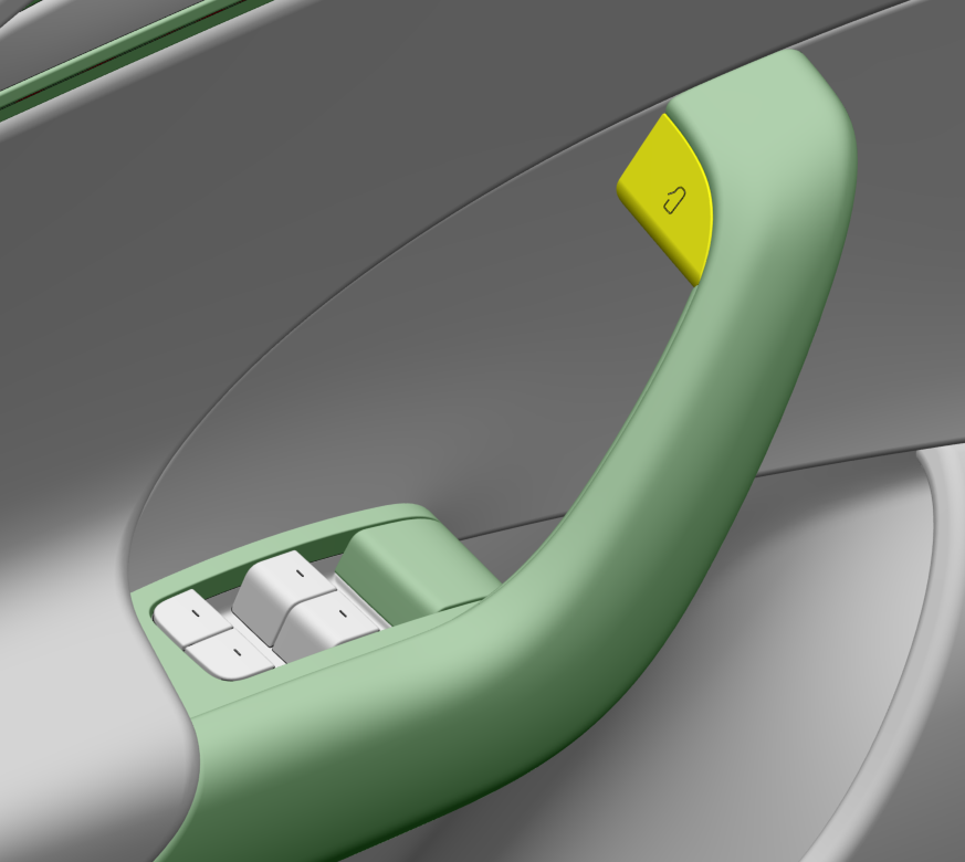
The switchpack contains four window switches and an LED. There are four LEDs, one for each button, but they share the same power supply inside the switchpack. The window switches are plastic push-pull levers mounted on the driver side armrest. These switches allow control of all four power windows in the vehicle. All other doors also have a single window switch used for control of that window only.
The switchpack is powered by the left vehicle controller (VCLEFT) on a Left Hand Drive (LHD) vehicle and powered by the right vehicle controller (VCRIGHT) on a Right Hand Drive (RHD) vehicle. The switchpack connector has six pins, four analog outputs for each of the buttons, one LED power, and one ground.
 |
|---|
| Driver Side Switchpack |
The switches have five positions. Each of the five positions corresponds to a known resistance (to ground) of the button. The corresponding vehicle controller reads this resistance value and knows the position of the switch.
Refer to the Specifications section for expected resistance values of the switches.
Window Switchlink
The three passenger windows can also be controlled locally (not from switchpack) by a single window switch. Each switch contains a single window switch and an LED. The single window switches are also powered by the corresponding vehicle controller. Each window switch has three pins, one analog output for the button position, one LED power, and one ground.
Window Regulatorlink
The window is moved up and down by a window regulator. The window regulators contain a DC motor with a right angle worm drive gear box, a DC motor controller, and a cable/pulley system which translates the rotation from the motor into linear motion of the windows.
The cables pull metal guides up the two rails on the regulator. These metal guides bolt directly to the window glass and hold the glass in place. The position of the glass can be adjusted by loosening the clips in the metal guides. This operation can be used to correct glass flush issues.
The window regulator motors are controlled by their corresponding vehicle controllers, see Vehicle Controller Left/Right.
The pinout of the window regulator is the same for all four windows. Always refer to the relevant wiring diagram but in general the pinout will look like the table below.
| Nr. | Label |
|---|---|
| 1 | Hall Effect Sensor 1 Output |
| 2 | Hall Effect Sensor Supply |
| 3 | Motor Supply P |
| 4 | Motor Supply N |
| 5 | Hall Effect Sensor Ground |
| 6 | Hall Effect Sensor 2 Output |
Window Glasslink
The four windows on 2021+ Model S and Model X vehicles are made of a 3.5 mm thick layer of tempered glass and a 1.1 mm thick layer of chemically strengthened glass (the same as is used on smartphones). The use of the chemically strengthened glass layer allows for a thinner and lighter window while still warranting the same strength. It also makes the window edges prettier. The two layers are bonded together by a 0.76 mm thick layer of an acoustic polymer layer which also dampens sound from outside of the vehicle. The small triangular A-pillar windows which are mounted to the side mirror assembly are non-laminated.
The glass attachment points for the front windows contain a hole for the A-pillar window clamp and a bonded-on PU holder for the B-pillar window clamp. The glass attachment points for the rear windows contain holes on both sides.
Vehicle Controller Left/Rightlink
The left window regulators are controlled by the left vehicle controller (VCLEFT), and the right window regulators are controlled by the right vehicle controller (VCRIGHT). The corresponding vehicle controller outputs MOTOR+ and MOTOR- signal to the window lift motor to move it up and down. Direction is controlled by changing polarity of the pins. Each window lift motor also has two hall sensor outputs, which input to the corresponding vehicle controller. This way the vehicle controller knows the window motor's position and speed, which allows it to have full control over the window lift motors. The switchpack is also hardwired to VCLEFT for Left Hand Drive (LHD) vehicles and to VCRIGHT for Right Hand Drive (RHD) vehicles.
VCLEFT and VCRIGHT are connected to each other via both Party controller area network (CAN) bus and Vehicle CAN bus. The Vehicle CAN bus is used to transmit relevant data about windows and switchpack to each other.
For more information on the vehicle controllers, refer to Electrical > Controllers and Wiring.
Specificationslink
Expected resistance of the window switches:
| Position | R min (Ohm) | R max (Ohm) | Description |
|---|---|---|---|
| Neutral | 25074.50 | 26625.50 | This is the undisturbed switch state. No effect on the window position. |
| Down | 3734.50 | 3985.48 | Pressing the switch down lightly will lower the window as long as the switch remains in this position. Use this setting to lower the window a custom amount. |
| Auto down | 1406.50 | 1513.34 | Pressing the switch down all the way will fully lower the window. The motor is driven regardless of switch position. Its state is latched until an overcurrent condition causes the motor state to unlatch. |
| Up | 611.10 | 668.88 | Same as Down, except the window moves up. |
| Auto up | 194.00 | 225.17 | Same as Auto down, except window moves up. |
Theory of Operationlink
Window Switchlink
This section describes the process of operating a window from a local switch, meaning the switch corresponding to the window adjacent and not on the driver switchpack. This is only the case for the three passenger power windows.
- The switch lever is pressed/pulled by the user.
- Each switch position causes a certain resistance (see Specifications) that is read by the corresponding vehicle controller.
- If the switch position is up/down partial, the vehicle controller will drive the motor until the window reaches the top/bottom of travel, or the switch position changes to any other state.
- If the switch position is up/down full, the regulator will drive the motor until the window reaches the top/bottom of travel, or the switch position changes to the opposite up/down full state.
Operating a window from the switchpack works exactly the same as operating a window from the local switch, except when the driver operates a window on the passenger side of the vehicle.
In this case, the vehicle controller that is hardwired to the switchpack (VCLEFT for LHD and VCRIGHT for RHD) reads the switch position and sends a CAN signal to the other vehicle controller over the Vehicle CAN bus. The other vehicle controller receives this CAN signal and controls the window accordingly.
Rear door window switches can be disabled from the vehicle UI, touch Controls > Quick Controls > Window Lock.
When Window Lock is enabled on the UI, both vehicle controllers will ignore inputs from the rear window switches. The rear windows will still operate when using the switchpack.
Specific Behaviorslink
- Window switches are locked out if the vehicle is externally locked and the vehicle power state is in OFF or CONDITIONING.
- Window switches are timed out after being pressed for more than 15 consecutive seconds due to button stuck detection.
Window Regulatorlink
Short Droplink
A short drop will occur every time the door is opened and the window is closed. The window will drop just enough for the glass to not catch on the upper bright trim seal. When the door is closed again, the window will move to the closed position. This is called "reverse short drop". If the door is not fully closed, the glass will not raise.
Ventinglink
The window regulators are classified for pinch detection, which allows for the remote closing features. Venting is one of those features that can be done remotely through the mobile app to open or close the windows. All four windows will vent at the same time. The vent position is slightly lower than the short drop position. The mobile app can also be used to close the windows again.
Thermal Protectionlink
The window regulator heats up as it raises and lowers the window. To prevent any damage to the window regulator internal components, vehicles controllers will limit window actuation if they sense the regulator temperature is above pre-defined threshold. Once the window regulator cools down, normal window operation will resume.
Pinch Detectionlink
Since software version 2023.2.12, vehicles are using a window pinch detection algorithm, which monitors window speed to identify potential pinch events and rely on pre-defined deceleration thresholds that may vary based on various factors.
In addition, the algorithm looks back at previous roll-up actuations to review if similar deceleration events were observed before and determine whether a current event is expected.
This is done by using "speed tables", which are built whenever the window performs a roll-up actuation, partial or complete.
Note
Speed tables are only used for limited window position ranges. Therefore, false pinches event may not be related to speed table build status.
Specific Behaviorslink
- Pinch override is disabled by default. User will only be able to hold a window switch up to manually roll-up for 30 seconds following a pinch detection event.
- If two or more pinch detection events occurs within 30 seconds without the window closing, a customer facing message will be displayed, advising user to hold the corresponding switch to close the window.
- If 15 pinch detection events occurred without the window closing, the window will become uncalibrated.
Serviceabilitylink
The window regulator is a non-serviceable component. If there is an issue with the window regulator operation, replace the component.
Service Routineslink
Window Calibrationlink
The window regulator contains an incremental encoder that tracks position changes. However, it does not report or keep track of the absolute position. Therefore, the regulator must learn the endpoints of the window. This is done through window calibration.
In addition, the window pinch detection algorithm saves the previous roll-up actuation speed into the speed table to inhibit pinch detection in certain scenarios.
Window calibration can be done manually by using the relevant window switch. Calibration can also be done automatically by running a Toolbox routine. To calibrate all windows at once, run PROC_VC_X_CALIBRATE-WINDOWS. To calibrate windows individually, use the following routines:
| Routine | Window |
|---|---|
| TEST-SELF_VCLEFT_FRONT-L_CALIBRATE-WINDOW | Front Left |
| TEST-SELF_VCRIGHT_FRONT-R_CALIBRATE-WINDOW | Front Right |
| TEST-SELF_VCLEFT_REAR-L_CALIBRATE-WINDOW | Rear Left |
| TEST-SELF_VCRIGHT_REAR-R_CALIBRATE-WINDOW | Rear Right |
When performing a software-initiated window calibration:
- Pinch detection is disabled.
- Window will roll down until it stalls to identify lower end-stop.
- Window will then roll up until it stalls to identify upper end stop.
- Pinch detection is enabled using pre-defined thresholds.
- Window will roll down again to the lower end-stop, and attempt an auto-up actuation to learn the speed table.
Window may detect a pinch event during the step #3 of the calibration when rolling-up. It will prevent the speed table from being built, but the end stop positions will still be calibrated, which allow auto-up and auto-down movement.
But without the speed table, the pinch detection algorithm might be more sensitive for certain windows and position ranges. It is therefore advised to manually perform a full roll-up actuation in a single movement to build it.
In some cases, a window regulator can lose calibration. Re-calibrating a window manually is easy and can therefore be done by the customer. Check if the window is calibrated again by shortly pressing the switch fully down or fully up. The window should move up or down automatically and stop at the expected positions.
Window Adjustmentlink
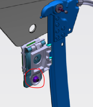
Windows can be adjusted in Y-direction, so inboard and outboard. On each slider of the glass regulator, there is a glass clamp. On the bottom side of the glass clamp, there is a jack screw (Allen key) that can be used to adjust the Y-direction of the window. The jack screw is locked with a 10mm nut. Loosen the locked nut and turn the jack screw clockwise to move the glass outboard. Turn the jack screw counter-clockwise to move the glass inboard. The total adjustment is 5mm, so 2.5mm towards each side from the neutral position.
 |
|---|
| Window Regulator Adjustment Screw |
Diagnosticslink
Window Statelink
The window state signal represents what the window is doing.
CAN signals:
VCLEFT_windowStateLFVCLEFT_windowStateLRVCRIGHT_windowStateRFVCRIGHT_windowStateRR