Filter Selection
Please select applicable type
Power Conversion Systemlink
Last updated: November 13, 2024
Overviewlink
The power conversion system (PCS) has three main functions:
- Pre-charging the HV bus on the vehicle prior to closing HV pack contactors
- Converting the pack DC high voltage down to low voltage to power the low voltage (low voltage) system of the vehicle and support the low voltage battery
- Converting AC to DC and stepping it up to charge the HV battery from AC wall power
AC and DC side terminals of the PCS are galvanically isolated.
The maximum AC charge current per line depends on the vehicle configuration. See Vehicle Configurations and Their Maximum Charge Current for more information.
Note
For more information on HV battery packs, see either Non-Structural High Voltage Battery or Structural High Voltage Battery.
On the low voltage side, the PCS can convert up to 2.5kW of power between the DC link and low voltage output. The illustration below displays the location of the PCS within the front Ancillary Bay.
Location of Power Conversion System (PCS)link
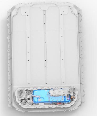
The PCS is located in the Ancillary Bay of the HV battery.
 |
|---|
| Location of the PCS in HV Ancillary Bay |
Accessing the PCSlink
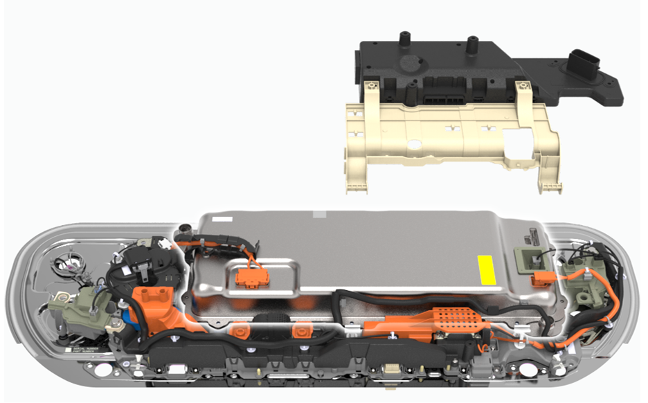
The High Voltage Controller (HVC) mounts to the PCS with a rotating plastic bracket. The bracket rotates to move the HVP out of the way to access the PCS.
 |
|---|
| Location of the PCS |
The PCS has a short connection to the HV. The current between the PCS and DC link flows in both directions.
- PCS to DC link/pack when AC charging
- Pack/DC link to PCS when supporting low voltage power
DC Connection to the PCSlink
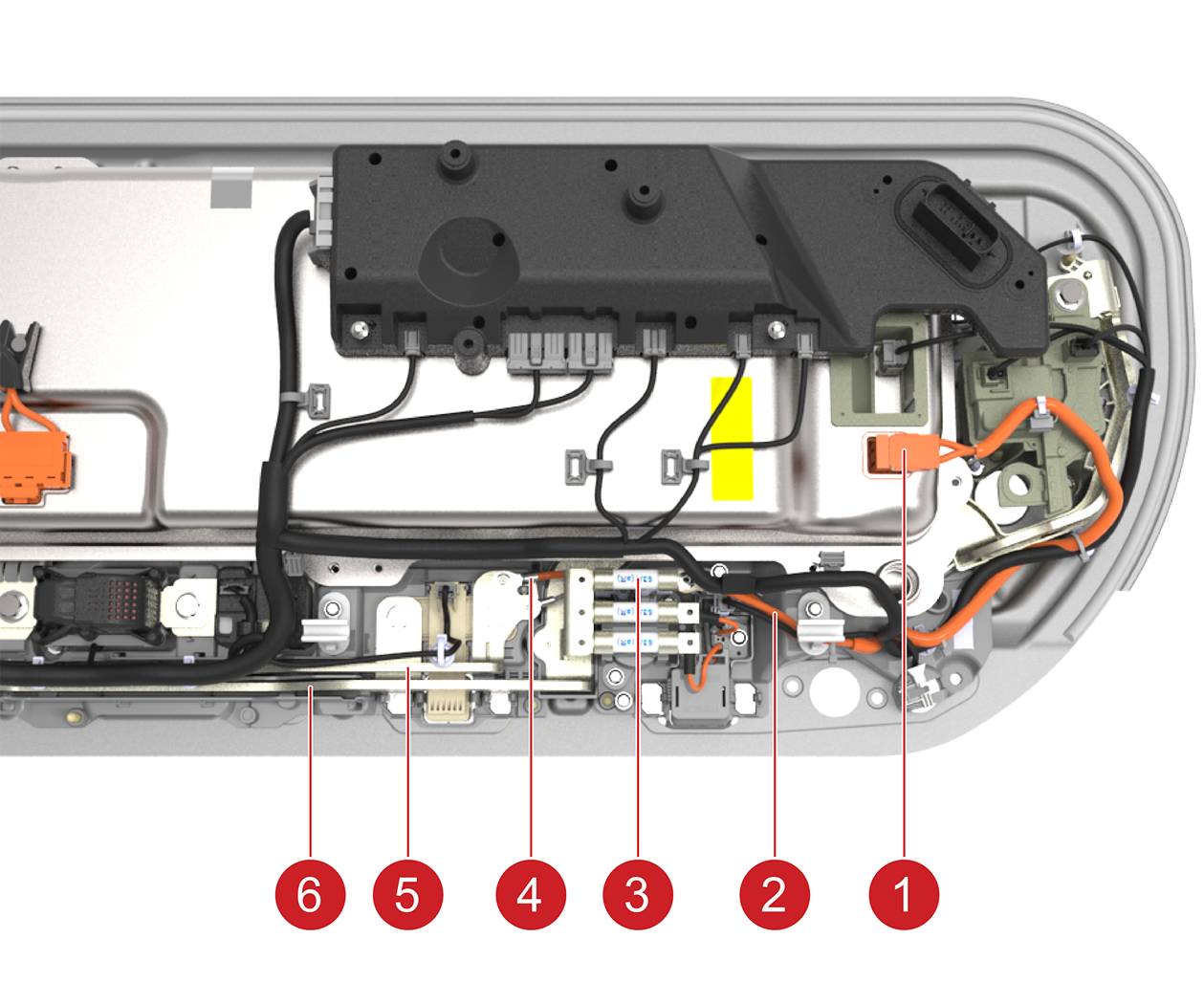
The PCS DC side is connected as follows to the pack DC link:
- The HV positive of the PCS is connected to the positive DC link busbar coming from the positive pack contactor.
- There is a 63A fuse in between the PCS HV connection and the busbar.
- The PCS HV negative connection is from a cable bolted on the main DC link negative busbar (via a round terminal) that connects to the negative pack contactor.
- The negative link from the DC link to the PCS is not fused in contrary to the positive one.
 |
|---|
| 1. HV DC connector to/from PCS 2. DC positive cable to/from PCS 3. 63A fuse on the DC positive leg of PCS connection 4. DC negative cable to/from PCS 5. DC negative busbar to negative pack contactor 6. DC positive busbar to positive pack contactor |
| Connection of PCS to DC Link HV |
AC Connection to the PCSlink
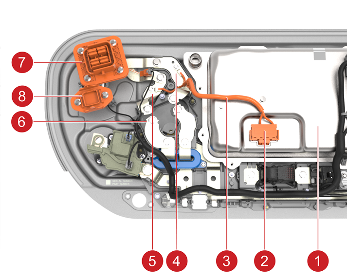
The PCS converts AC input from wall power through the charge port to DC voltage when charging the HV battery. The PCS has a dedicated connection to the HV battery inlet charge port busbar connector for this.
 |
|---|
| 1. PCS 2. AC input to the PCS 3. Harness for AC input to PCS 4. Connection of PCS AC input 1 to charge port connector busbar 5. Connection of PCS AC input 2 to charge port connector busbar 6. Fast charge contactors 7. Connector to charge port harness 8. three-phase AC input Connector for EMEA and APAC |
| Connection of PCS to AC Input |
On Model Y and Model 3 vehicles built in late 2020 and later, the charge port inlet uses solid aluminum busbars with a bolted-joint type connection.
 |
|---|
| 1. Slide-in connector charge inlet - Model 3 vehicles built up to late 2020 2. Charge port inlet bus bar or bolted style - Model Y and Model 3 vehicles built in late 2020 and later |
| The Two Styles of Charge Port Inlets |