Body Controllerslink
Last updated: October 20, 2023
Body Control Modulelink
 |
|---|
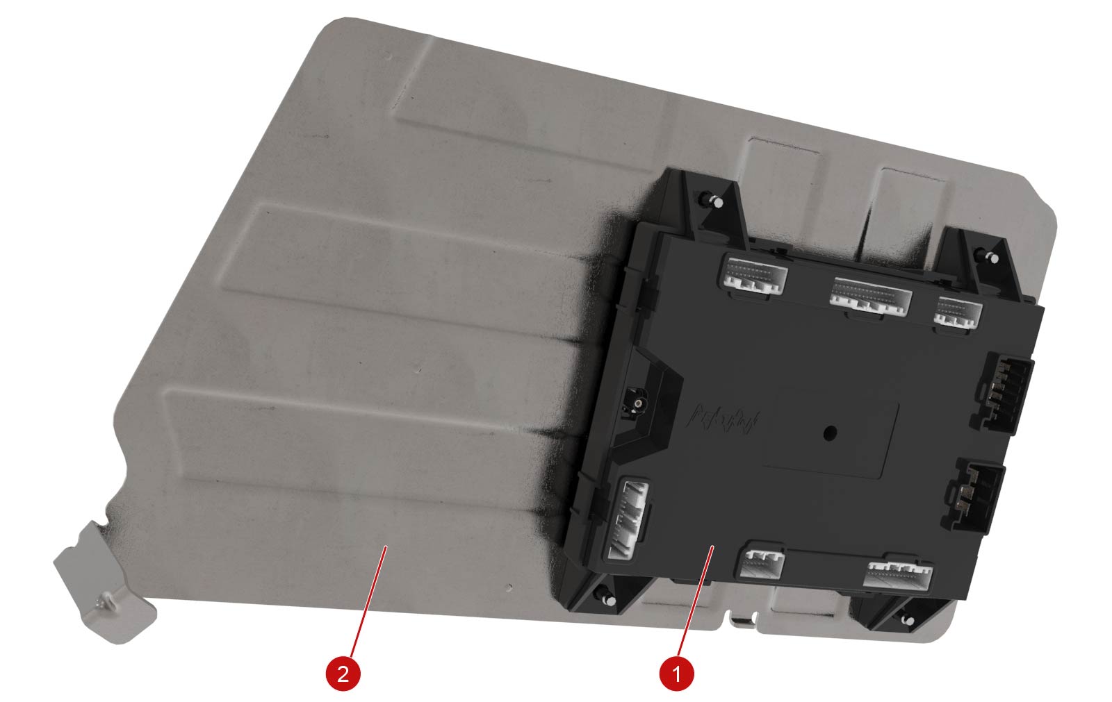
| 1. Body control module 2. Cover plate |
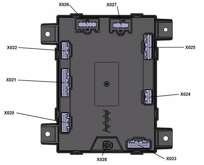 |
| Connectors |
| Body Control Module |
The BCM is located in the front passenger footwell, behind a cover plate. The cover is secured by 4 screws and there are 8 harness connectors and a single coaxial antenna connector.
The BCM controls the lock/unlock and opening behavior of all closures on the Model S. It communicates with the door control modules to manage door handle behavior, locking/unlocking, and door latch operation. The BCM directly controls the liftgate latch, and communicates with the liftgate control module to manage power liftgate operation (if equipped). The BCM directly controls the operation of both hood latches.
The RKE (remote Keyless Entry) antenna is connected to the BCM, which processes RKE requests and takes action accordingly, whether to directly control an actuator, or to send a Controller Area Network (CAN) message to another control module to carry out an action. The Passive Entry antennas, which detect the presence of the key fob, are connected to the BCM (with the exception of the antennas in the ends of the instrument panel, which are connected to the door control modules). The BCM also receives door ajar inputs directly from the door latches.
Other inputs to the BCM include the glove box door release switch and the liftgate release switch. Both receive power from the BCM for illumination. The glove box switch is a simple momentary switch that completes a path to ground on a discrete signal circuit. The liftgate release switch does not have a discrete signal circuit, but contains resistors that vary the current draw on the power supply circuit from the BCM. Standard liftgates have one action switch with one resistor. Power liftgates have a dual action switch with two resistors. The BCM detects the current changes and interprets the switch input signals as "release" for standard liftgates, and as "open" or "close" for power liftgates.
The BCM controls exterior and interior lighting. It receives signals from several sources:
- CAN messages from the steering column control module and the touchscreen control the headlamp and turn signal operation.
- CAN messages from the Drive Inverter control brake light operation in response to regenerative braking, and reverse light operation when the Reverse gear is selected.
- CAN messages from the EPB (Electronic Park Brake) activate the brake lights in response to dynamic parking brake application.
- A direct input from the brake pedal switch turns on the brake lights when the pedal is pressed.
- CAN messages from the Electronic Stability Program (ESP) module activate the brake lights during a stability control intervention.
- The hazard switch is also a direct input to the BCM.
Each of the headlamp assemblies and the outer brake/tail light assemblies has a discrete output circuit to the BCM, to indicate a light outage. The other lights are monitored for current draw in order to detect failures.
Door Control Modulelink
 |
|---|
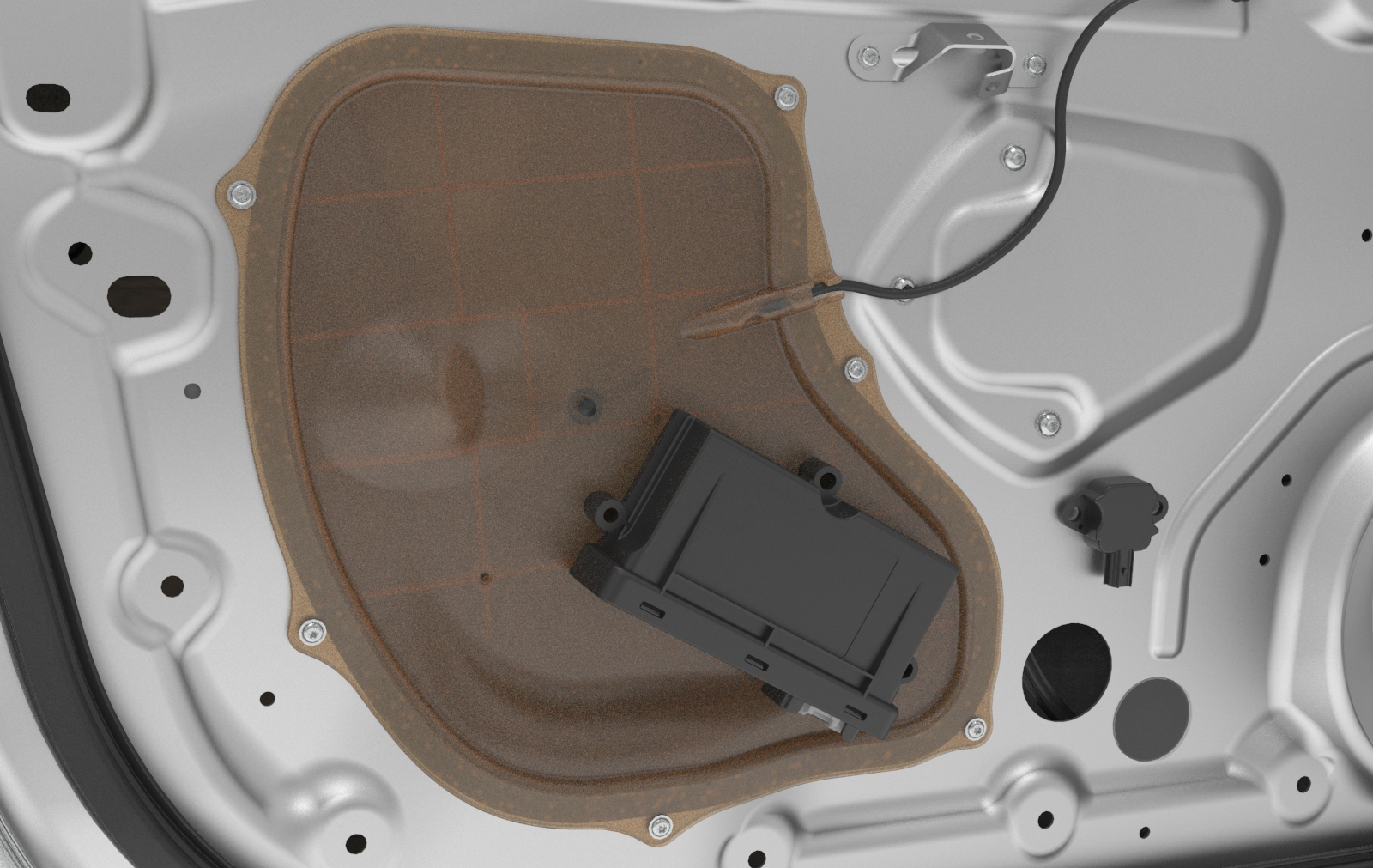
| Door Control Module |
A door control module is located in each front door. Each door control module controls the front and rear door for its respective side.
The driver door module (DDM) and the passenger door module (PDM) are identical. These modules self-identify their position on the vehicle through a combination of an output from the Gateway (GTW), and unique vehicle harness wiring. Another GTW output determines whether the vehicle is Left Hand Drive (LHD) or Right Hand Drive (RHD). The passenger door wire harness grounds an input circuit of the module, which identifies it as the PDM. From these two inputs, each door module determines if it is on the LH or RH side of the vehicle, and whether it is the DDM or PDM. When a module is replaced, a "learn car" command stores the identity in non-volatile memory.
The door control modules manage operation of the door latch, exterior door handle, power window motor, outside mirror, and door lock/unlock behavior. The door control modules are connected to the body CAN bus, and each one has a discrete LIN bus that is used to communicate with the outside door handles, the power window motors, and on the LH side, the driver's switchpack (window/mirror controls). The other window switches do not communicate directly with the door control module. The door control modules act as a CAN/LIN gateway for controlling window and mirror operation, and for updating door handle firmware.
Liftgate Control Modulelink
 |
|---|
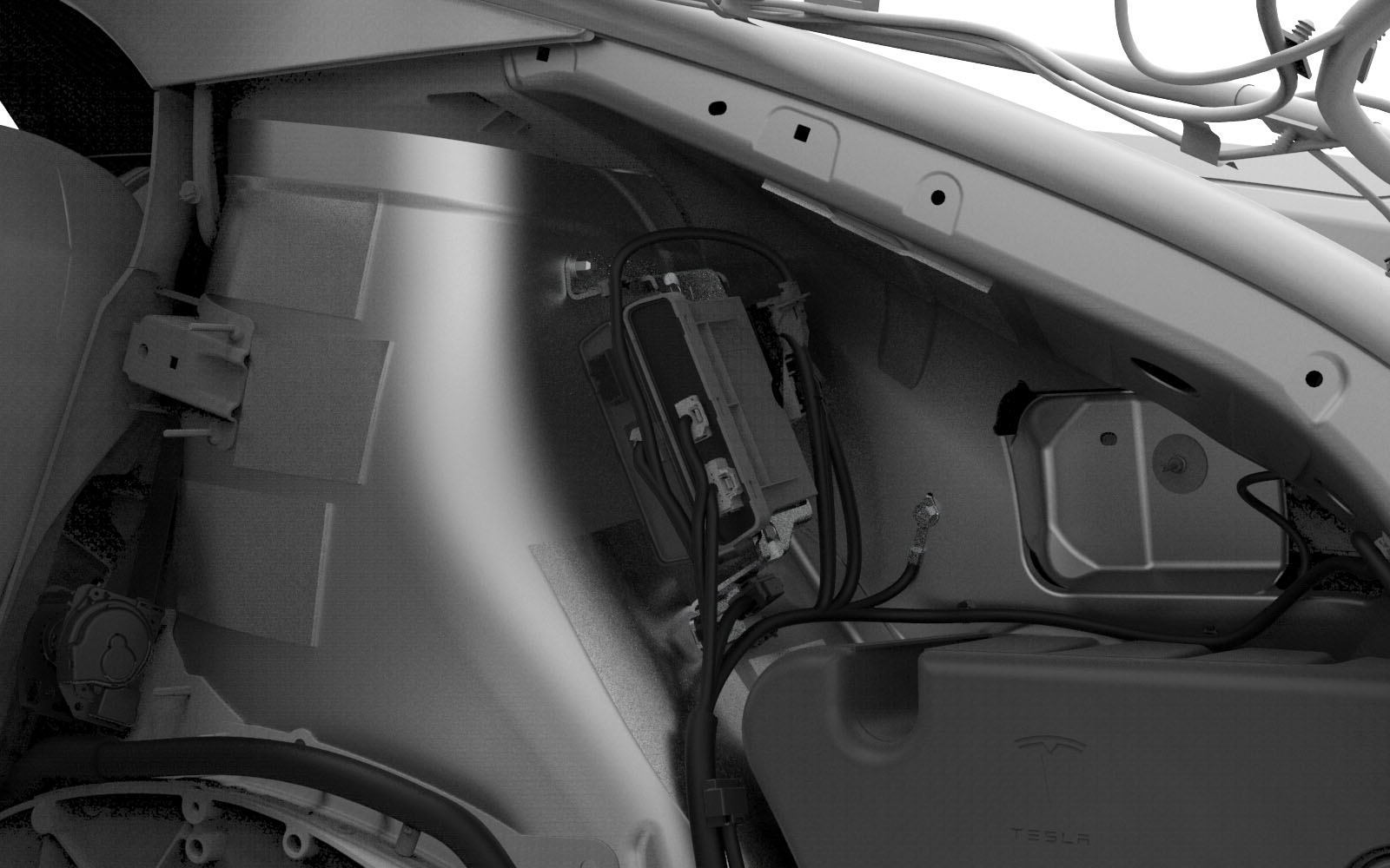
| Liftgate Control Module |
This control module operates the power lift struts and stores memory settings for the liftgate opening limit.
CANlink
 |
|---|
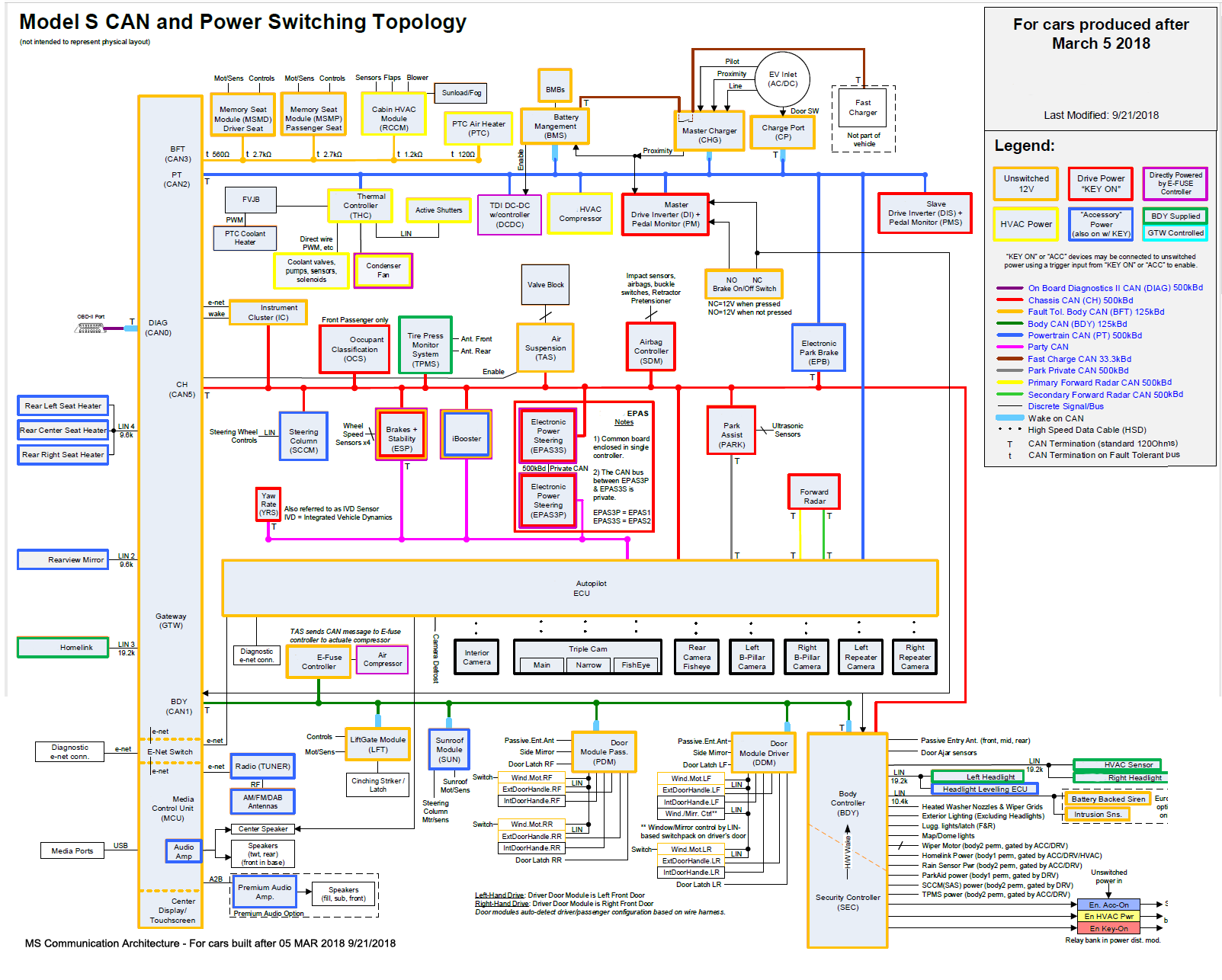
Download the PDF of this image: Communication Architecture for Model S PDF
Communication Architecture for Model S Built after March 5th 2018
Bus Mappinglink
Model S/X CAN bus networks are mapped to different ID numbers depending on where they connect to the microcontroller within the gateway.
| Bus ID | Bus Name |
|---|---|
| 0 | OBD2/Diag |
| 1 | Body |
| 2 | Powertrain |
| 3 | Body Fault Tolerant |
| 5 | Chassis |