High Voltage Distributionlink
Last updated: December 11, 2024
Overviewlink
This document focuses on the distribution of high voltage power among all HV components. Each high voltage component that is not directly used for HV distribution is detailed in other Theory of Operation documents.
The HV distribution architecture is influence by the powertrain configuration of the vehicle.
- All configurations have the high voltage (HV) battery located in the chassis of the vehicle, between the 4 wheels of the car.
-
Long Range configuration has one front drive and one rear drive unit:
- The front drive unit is located on the front subframe, between each front wheel.
- The rear drive unit is located on the rear subframe, between each rear wheel.
-
Tri-motor has one front drive unit and two rear drive units, one for each rear wheel:
- The front drive unit is located on the front subframe, between each front wheel.
- Both rear drive units are located next to each other on the rear subframe, between each rear wheel.
For cabin and powertrain thermal heating / cooling , the HV system uses a heat pump. The HV system does not use a PTC heater (dedicated cabin heater), nor does it use a coolant battery heater. The HV system uses the heat pump to generate heat in the cabin and uses waste heat mode in the drive inverter, along with the heat pump to generate heat for the HV battery. For more details, refer to the section 'High Voltage Battery Thermal Management' in the Structural High Voltage Battery Theory of Operation.
The Cybertruck compressor is specifically designed to handle an 800V architecture and High Voltage Interlock Loop (HVIL) over Controller Area Network (CAN).
The HV distribution design minimizes complexity, cost, and weight, with most connections consolidated within the HV battery and no separate HV connection components. The HV system includes the following components:
- High voltage battery serves as the primary energy source for the vehicle.
- Drive inverter(s) featuring waste heat mode, which heats the coolant and eliminates the need for a dedicated coolant heater component.
- The Power Conversion System (PCS), located in the HV battery ancillary bay, which supports
- DCDC conversions
- MV to HV conversion for precharging the DC link bus before closing pack-contactors.
- HV to MV conversion once contactors are closed to power the MV bus and manage MV battery state of charge.
- AC to DC conversion for charging vehicle on AC power.
- HV to AC for Powershare features (AC outlets and home power backup)
- Cabin heating, ventilation, air conditioning (HVAC) system.
- High Voltage Devices to manage high voltage distribution
- Battery pack contactors manage the energy transfer from the HV battery to the DC link, supplying power to other high voltage components.
- Fast charge contactors used to facilitate direct current charging.
- Pyro disconnects to interrupt the HV loop when necessary
- Shunts to measure current flow
- AC junction box to interconnect AC outlets, PCS and charge port
- Charge port assembly and charging harness for charging.
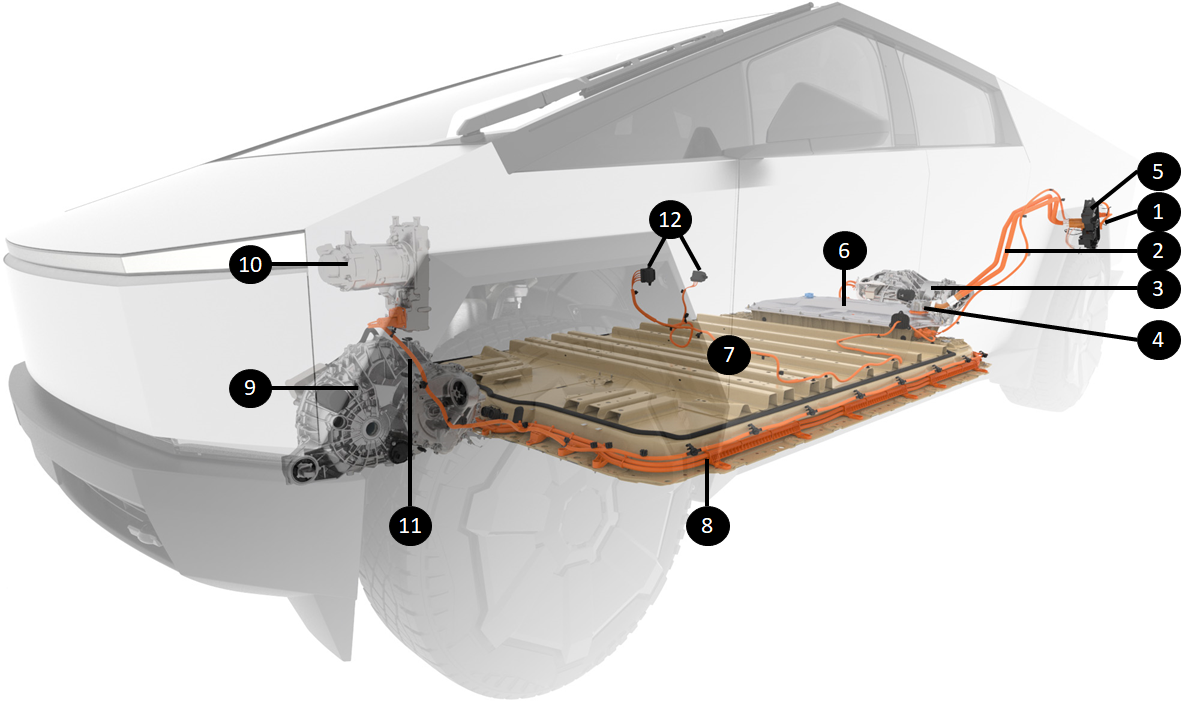
The illustration below provides a general overview of how the HV is distributed from the HV battery to all HV components, which creates the powertrain of the vehicle. The representation shows a Dual Motor configuration with two drive units .
 |
|---|
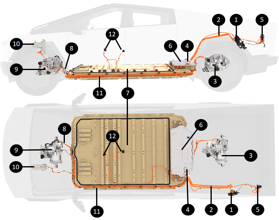 |
| 1. Charge port 2. Charge port busbars 3. Rear drive unit 4. HV battery inlet charge port busbar connector 5. Truck bed AC outlet 6. Ancillary Bay 7. Structural High voltage battery 8. HV cable to Front Drive Unit 9. Front Drive Unit 10. Heat Pump Compressor 11. Routing of Front Drive Unit and Compressor from Rear of HV battery to Front of vehicle 12. Cabin AC outlets |
| HV Distribution Overview (Dual Motor Configuration) |
Most of the HV connections and branching are located inside the ancillary bay of the HV battery.
Location of High Voltage Componentslink
Location of High Voltage Batterylink
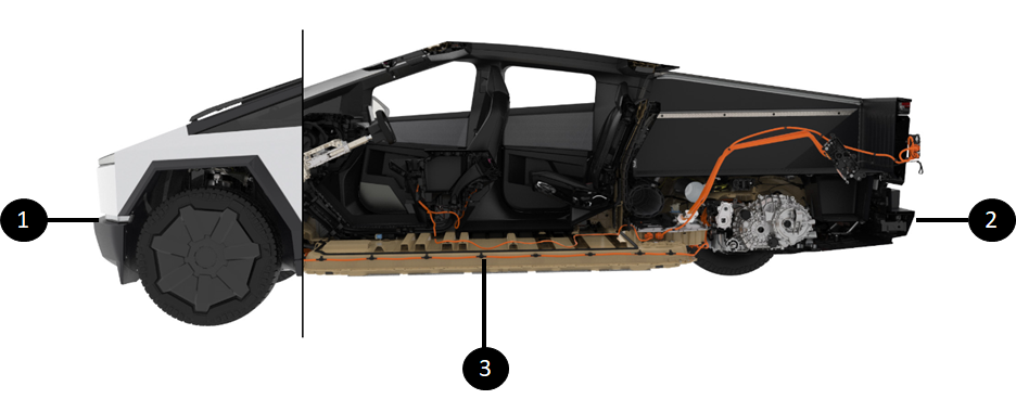
The HV battery is located between the rear and front subframes of the vehicle. The high voltage battery is mounted to the chassis of the vehicle, from underneath. This gives easy access to removal and installation from the bottom of the vehicle and gives the vehicle exceptional performance due to the lower center of gravity.
The HV battery is a structural HV battery. It is designed to be part of the vehicle body and carries structural properties for the chassis and body of the vehicle. The structural HV battery enclosure is integrated with the Body-in-White and provides front crash backup structure as well as interior seat mounts. The structural HV battery not only provides rigidity to the chassis for vehicle dynamics and crash response, but it also acts as the floor of the vehicle. The seats, carpet, center console, and other interior trim is mounted directly onto the structural HV battery.
The rear ancillary bay of the HV battery, which contains most of the HV devices of the HV battery, is located at the top rear of the HV battery on top of the modules. For more details, refer to the Structural High Voltage Battery Theory of Operation.
 |
|---|
| 1. Front of vehicle 2. Rear of vehicle 3. HV battery |
| Structural HV Battery Location |
Location of Drive Unitslink
The Cybertruck Tri-motor configuration has three drive units in total. The Long Range configuration has two drive units, and there is no Rear Wheel Drive (RWD) version with a single drive unit.
For Tri-motorconfigurations, there are two drive units located in the rear subframe between the two rear wheels and one front drive unit located in the front subframe between the two front wheels.
Note
The two rear drive units come as a single assembly in service. The rear and right inverters can be serviced as independent parts, but the drive units come as a single unit with both drive units.
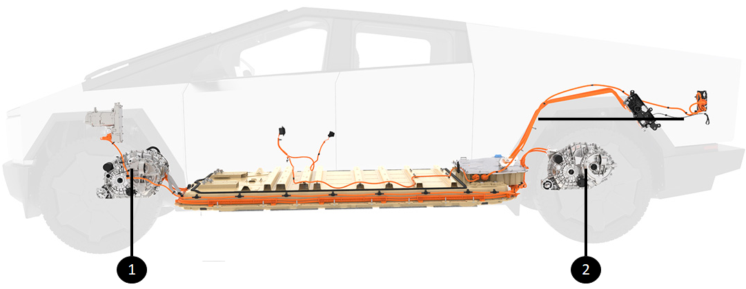
For Long Range/Dual Motor configurations, the rear drive unit is located in the rear subframe between the two rear wheels and the front drive unit is located in the front subframe between the two front wheels.
See the Drive Unit Theory of Operation for more details.
 |
|---|
| 1. Front drive unit 2. Rear drive unit |
| Drive Unit Locations (Dual Motor Configuration) |
Location of HV A/C Compressorlink
The HV A/C compressor is located between the firewall and the front trunk of the vehicle. The location of the heat pump compressor is behind the firewall for both the structural and non-structural HV battery vehicles. However, the firewall is located in different places in each variant.
To reduce further Noise, Vibration, and Harshness (NVH), the compressor on Cybertruck is suspended from the megabeam.
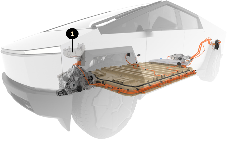 |
|---|
| 1. HV A/C compressor |
| HV A/C Compressor Location |
Location of Power Conversion Systemlink
The functions of AC charging and DCDC conversions are handled by the Power Conversion System (PCS). There is no dedicated AC charger or DCDC device in the vehicle.
The PCS (highlighted in red) is located on the right side of the ancillary bay of the HV battery. For more details, refer to the Structural High Voltage Battery Theory of Operation.
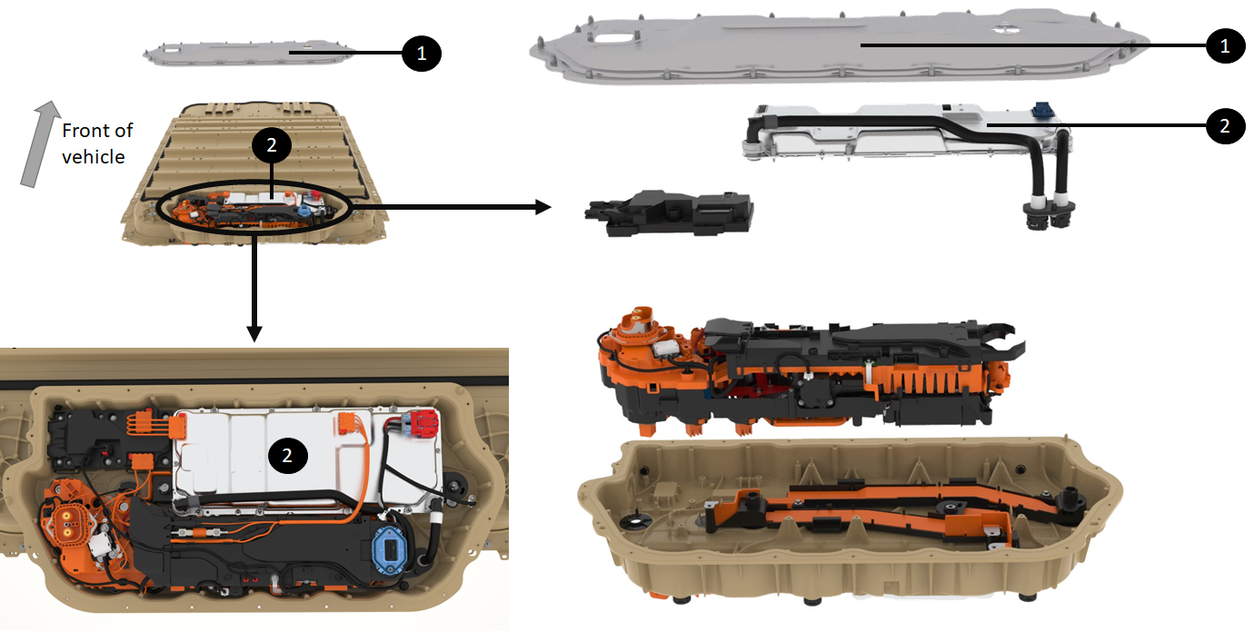 |
|---|
| 1. Ancillary Cover 2. PCS2 directly underneath |
| Location of the PCS2 |
High Voltage Build Up in the High Voltage Batterylink
The Cybertruck can either be set in series mode for 800V (full pack voltage) operations or parallel mode for 400V (half pack voltage). Series mode is the default state of the HV battery. It is used for driving, AC charging, support mode, and everything else that is not DC fast charging on a DC charge unable to provide 800V.
The Dual Pole Dual Throw (DPDT), located in the ancillary bay , connects the cell array either in series or parallel mode.
The general idea is that when charging at stations that are unable to provide 800V, the DPDT will switch to parallel mode where:
- Cell array 1 and 3 are in series
- Cell array 2 and 4 are in series
- These two sets, each comprising two cell arrays in series, are then connected in parallel.
High Voltage Battery and High Voltage Component Interfaceslink
DC Link to Power Conversion Systemlink
Although the PCS is not used when fast charging, it is connected to the DC link of the HV battery for the following functions:
- Precharging the DC link but to pack voltage before closing contactors.
- Stepping down high voltage from the HV battery to lower voltage to support the mid voltage bus of the vehicle.
- Converting DC HV from the HV battery to AC for the AC outlets and home back up functionalities
For more details, see Structural High Voltage Battery Theory of Operation.
The DC side of the PCS DC is connected as follows to the HV battery DC link:
There are two connections from the HV battery to the medium voltage system. The first connection is made before the contactors, ensuring that the PCS always receives high voltage from the HV battery, even when the contactors are open. This connection powers the HV battery side DCDC converter, which is permanently connected to the HV battery. The second connection is made after the contactors and only provides high voltage to the PCS when the contactors are closed, powering the switched DCDC converter that is connected to the HV battery only when the contactors are closed.
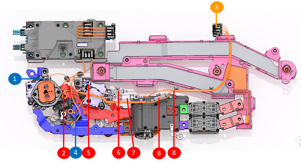 |
|---|
| 1. Always powered negative connection on negative contactor for always on DCDC 2. Lug connection at FC contactor for DC Link positive HV to PCS 3. HV connector to PCS 4. Lug connection for DC Link positive HV to PCS 5. Always powered positive connection on positive contactor for always on DCDC 6. Sand fuse integrated in harness for always ON DCDC 7. Sand fuse integrated in harness for PCS2 8. Second Sand fuse integrated in harness for always on DCDC |
| Connection of PCS to DC Link HV |
AC Input to Power Conversion Systemlink
The PCS converts AC input from wall power through the charge port to DC voltage when charging the HV battery.
The AC junction box (ACJB) serves as the link between the charge port and the PCS. This configuration enables power from the charge port to be used directly by the truck bed AC outlets when one or multiple loads are connected to the plugs.
Note
The cabin AC outlets are not directly connected to the charge port. The image below shows the PCS to charge port bus bars at the fast charge contactor assembly.
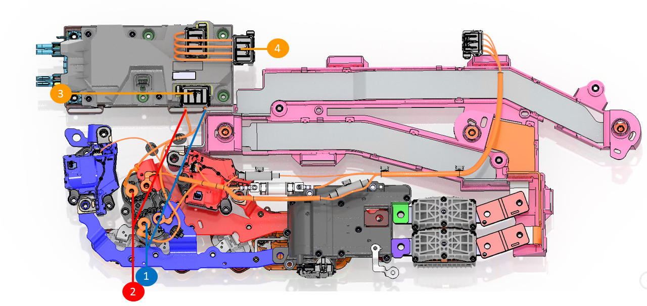 |
|---|
| 1. Eyelet for connection of neutral of charge inlet to harness to ACJB 2. Eyelet for connection of AC phase from charge inlet to harness to ACJB 3. ACJB connector for connection to charge inlet 4. Connector from ACJB to PCS for AC connection from charge inlet |
| Connection of PCS to DC Link HV |
Charge Port to DC Linklink
Fast Charge (FC), also known as Direct Current (DC) charging, involves the vehicle receiving DC voltage directly into the HV battery without any internal conversion system. The conversion from Alternating Current (AC) to DC occurs outside the vehicle, like in Supercharger or CHAdeMO stations. The HV battery uses FC contactors to connect each side of the DC link to the charge port cables.
The DC Connection to the PCS section describes the charge port busbar route from the HV battery charge port inlet to the FC contactors assembly, which closes during Fast Charge, allowing a direct connection between the HV battery DC link and the HV battery inlet charge port connector.
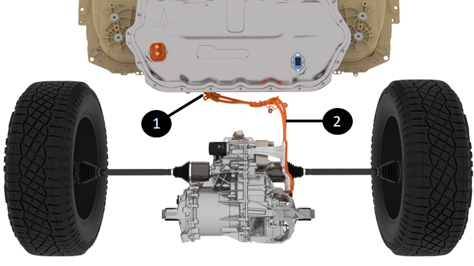
Front Drive Unit and HV A/C Compressorlink
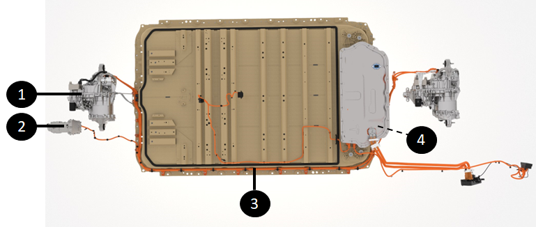
The front drive unit and HV A/C compressor are both located in the front of the vehicle, between the firewall and the front trunk (or frunk).
HV cables for each HV component run from the back of the HV battery, passing under the ancillary bay to the front (along the driver side of the HV battery), extending toward the front of the vehicle. The image below illustrates the locations of the compressor and front drive unit, along with the high voltage routing from the rear of the HV battery to the front of the vehicle.
 |
|---|
| 1. Front drive unit 2. Compressor 3. Compressor and front drive unit HV cables running along the HV battery 4. Compressor and front drive unit HV connections at back of HV battery, under the ancillary bay |
| Location of HV Connections to the HV A/C Compressor |
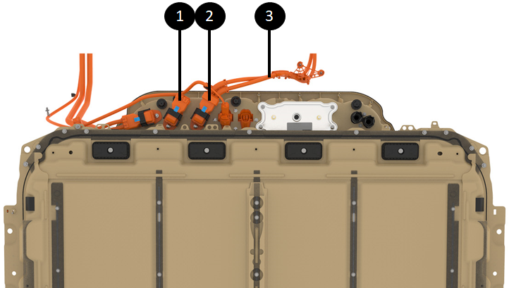
 |
|---|
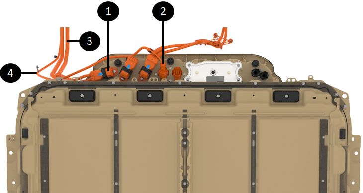
| 1. Front drive unit HV cable connection at HV battery 2. Compressor HV cable connection at HV battery 3. Front drive unit HV cable 4. Compressor HV cable |
| Front Drive Unit and HV A/C Compressor HV Connections |
The high voltage connection at the compressor is made on the front side for easier access.
 |
|---|
| HV Connection to the HV A/C compressor |
High Voltage Battery to Rear Drive Unitlink
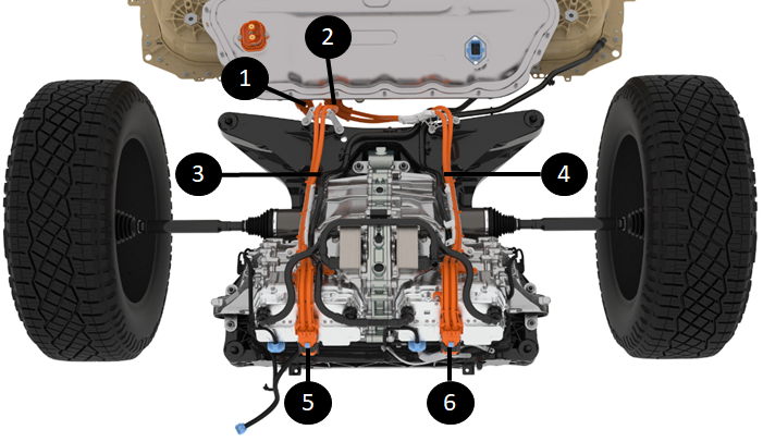
The HV routing for the rear drive units originate from the high voltage connectors located at the rear of the HV battery.
- The Tri-motor configuration has two harnesses going to each drive unit.
- The Long Range configuration has one harness going to the single drive unit.
The same HV battery is used for Long Range and Tri-motor configurations. For the Long Range configuration, a dummy plug is installed on the HV connector of the HV battery intended for the second drive unit of Tri-motor configurations.
 |
|---|
| 1. Rear Left Drive Unit HV connection underneath ancillary bay - RDUL-HV-AT-HVBATT 2. Rear Right Drive Unit HV connection underneath ancillary bay - RDUR-HV-AT-HVBATT 3. Rear Left Drive Unit HV cable 4. Rear Right Drive Unit HV cable 5. Rear Left Drive Unit HV connection - RDUL-HV-AT-RUDL 5. Rear Right Drive Unit HV connection - RDUR-HV-AT-RUDR |
| HV Connections Routing to Rear Drive Unit (Tri-motor Configuration) |
 |
|---|
| 1. Rear Drive Unit HV connection underneath ancillary bay - RDU-HV-AT-HVBATT 2. Rear Drive Unit HV cable |
| HV Connections Routing to Rear Drive Units (Long Range Configuration) |
 |
|---|
| 1. Rear Left Drive Unit HV cable connection at HV battery RDUL-HV-AT-HVBATT (shown in Dual Motor with a dummy plug) 2. Rear Right Drive Unit HV cable connection at HV battery RDUR-HV-AT-HVBATT 4. Rear Right drive unit HV cable |
| HV Connections Routing to Rear Drive Units at HV battery |
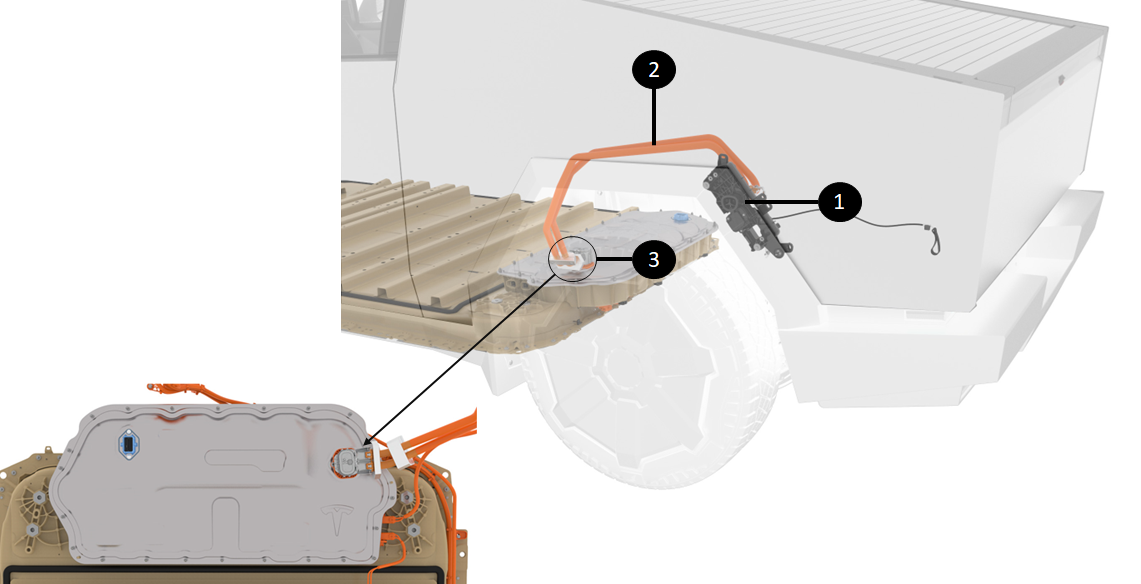
Charge Port Connectionslink
The high voltage routing for the charger port starts from the high voltage connector at the rear of the HV battery. From there, refer to the section on Alternating Current (AC) and Direct Current (DC) connection to Power Conversion System (PCS) internally to the HV battery.
 |
|---|
| 1. Charge port 2. Charge port harness to HV battery 3. HV battery inlet charge port busbar connector CP-HV-AT-HVBATT |
| Charge Port HV Connections |