Low Voltage Controllers and Wiringlink
Last updated: January 30, 2023
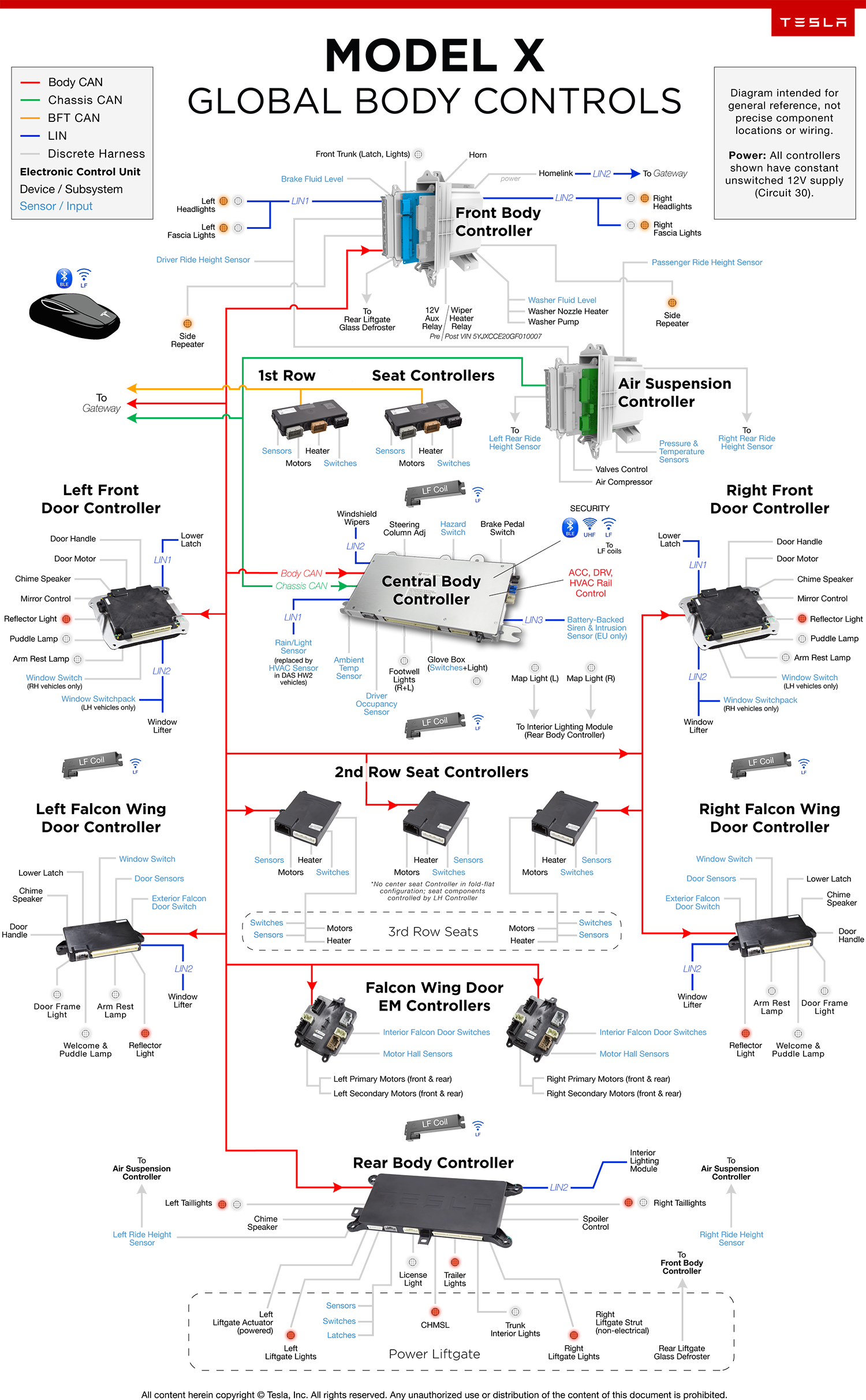
Body Controls Overviewlink
 |
|---|
Controller Area Network (CAN)link
Overviewlink
 |
|---|
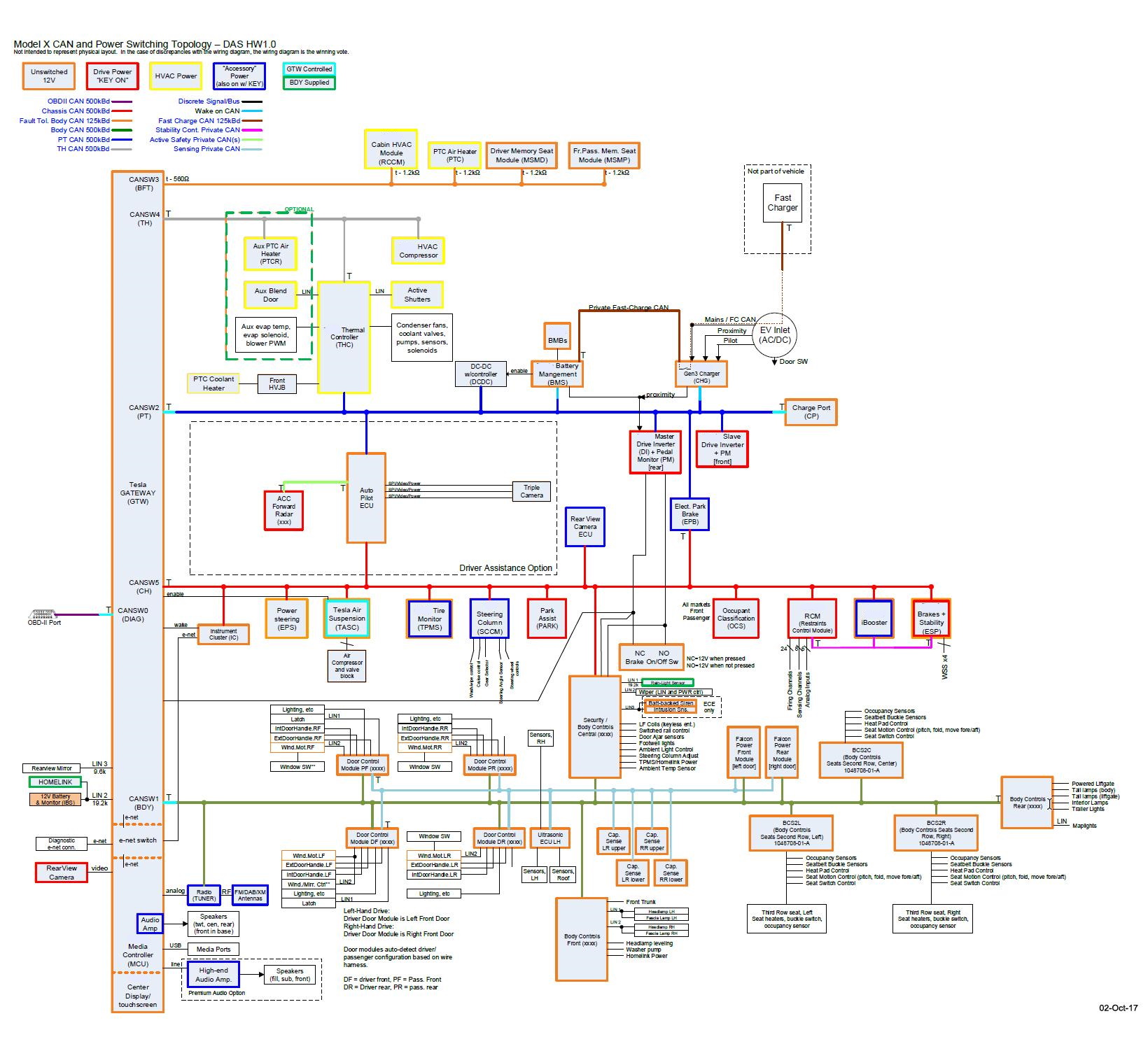
| CAN Overview, Driver Assistance System (DAS), Hardware Version 1.0 |
 |
|---|
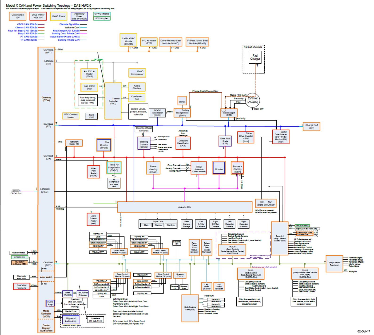
| CAN Overview, DAS 2.0 |
 |
|---|
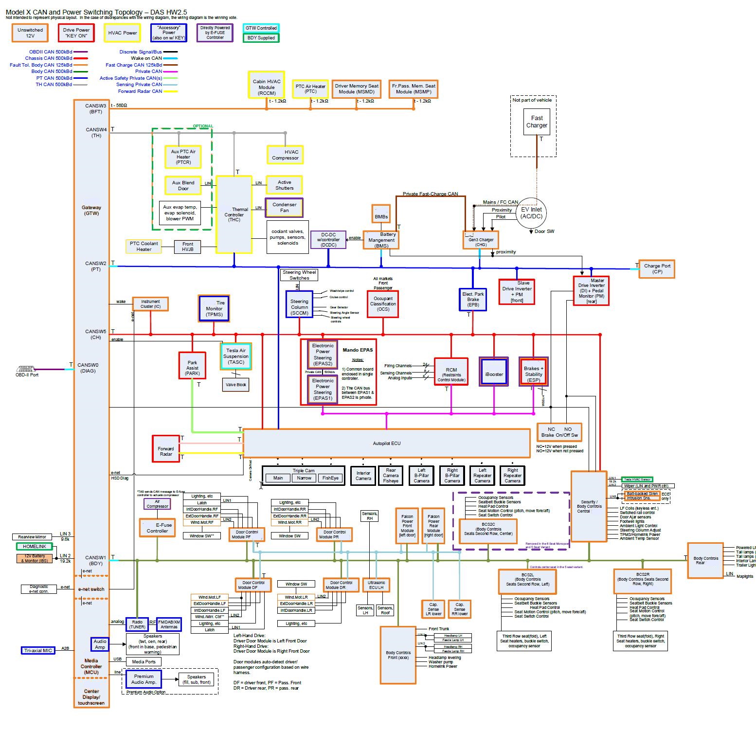
| CAN Overview, DAS 2.5 |
Bus Mappinglink
Model S/X CAN bus networks are mapped to different ID numbers depending on where they connect to the microcontroller within the gateway.
| Bus ID | Bus Name |
|---|---|
| 0 | OBD2/Diag |
| 1 | Body |
| 2 | Powertrain |
| 3 | Body Fault Tolerant |
| 5 | Chassis |
Model X has a total of 10 Controller Area Network (CAN) buses. Of the 10 CAN buses, 6 are connected to the Tesla Gateway (GTW). The other buses are considered private CAN networks utilized for Driver Assistance features, Fast Charging, Stability Control, and Rear Door Sensing. Individual controllers use these buses to transfer data between the different controllers and networks. The CAN buses are:
- Chassis
- Body
- Body - Fault Tolerant
- Powertrain
- Thermal
- OBDII (On-Board Diagnostics II)
- Active Safety (Not connected to GTW)
- Fast charge (Not connected to GTW)
- Stability control (Not connected to GTW)
- Rear Door (Sensing) (Not connected to GTW)
All CAN circuits consist of a twisted pair of copper wires. This type of construction reduces electromagnetic interference. Each controller on a particular CAN bus exchanges information with other controllers, but data is passed through the GTW if it needs to go to a controller on a different CAN bus.
The CAN lines are integral with the vehicle harnesses, and they can be recognized by the following pair of wires in adjacent terminals in the connector of the relevant controller:
- Body Fault: VT and VT/WH
- Body: BN and BN/WH
- Chassis: GN and GN/WH
- Rear Door: GY and GY/WH
- Powertrain: RD and RD/WH
- Thermal: BU and BU/WH
A ‘T’ or ‘t’ on the end of each node indicates a termination resistor. More information on each of these is given in the individual CAN descriptions.
The 4 wheel speed sensors and the air suspension compressor wires have a diagonal slash across them. This indicates that more than one wire is used in the implementation.
CAN Bus Descriptionslink
OBD-II CAN Bus - 500 Kblink
The OBD connector is the only component on the OBD CAN. It connects directly to the GTW.
The TPMS tool connects through the OBD-II port.
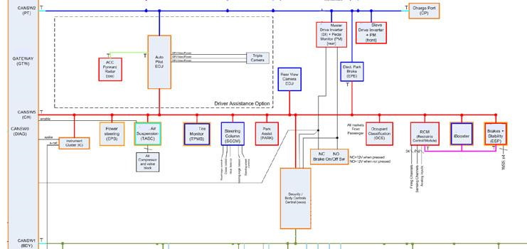
Chassis CAN Bus - 500 Kblink
 |
|---|
The chassis CAN bus connects the following controllers:
- Tesla Gateway (GTW) - T
- Instrument Cluster (IC)
- Security / Central Body Control Module (BCCEN)
- Tire Pressure Monitoring System (TPMS)
- Air Suspension (EAS)
- Active Safety (TASC)
- Restraints Controller
- Bosch iBooster (IBST)
- Bosch Brakes & Stability (ESP)
- Occupant Classification System (OCS)
- Steering Column Control Module (SCCM)
- Electric Power Steering (EPS)
- Electric Park Brake (EPB) - T
- Park Assist Controller (PARK)
Each controller on the schematic is identified by a colored outline. The outline indicates the controllers power source operation (always powered, ON with Drive Rail, ON with ACC Rail, etc.), along with additional controller wake conditions (e.g. GTW controlled enable).
The Air Suspension, EPS, ESP, and ESP controllers have a twin color outline. This denotes that different functions within the controller are powered through different sources. The TPMS controller’s color indicates that its power is supplied by the body controller.
Note: The air suspension ECU also has an enable line from the GTW. When the drive rail is switched on, this enable signal wakes the ECU. The drive rail is on whenever P, R, N, or D is showing under the speedometer. When the drive rail is off, the enable signal is lost. The ECU enters post-run mode, then sleep mode, and finally the system switches off.
The chassis CAN has a ‘T’ on 2 nodes. This indicates the 2 terminating nodes of the bus; each adds 120 ohms to the CAN bus. The terminating nodes are located at the end of each bus, to help with the reflection of the messages. A perfectly terminated CAN bus reads 60 ohms, which is the equivalent resistance of the two 120 ohm terminators in parallel.
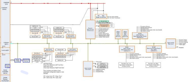
Body CAN Bus - 500 Kblink
 |
|---|
The Body CAN connects the following controllers:
- Tesla Gateway (GTW)
- Radio/Tuner
- Front Driver Door Control Module (BCFDM)
- Front Passenger Door Control Module (BCFPM)
- Rear Driver Door Control Module (BCRDM)
- Rear Passenger Door Control Module (BCRPM)
- Front Body Control Module (BCFRONT)
- Security / Central Body Control Module (BCCEN)
- Body Controls / Second Row Seat Left Control Module (BCS2L)
- Body Controls / Second Row Seat Right Control Module (BCS2R)
- Body Controls / Second Row Seat Center Control Module (BCS2C)
- Rear Door Power Front Module
- Rear Door Power Rear Module
- Rear Body Control Module (BCREAR) - T
All modules on the Body CAN are powered via unswitched 12V power except for the Radio/Tuner which is powered via ACC Rail.
The Body CAN has a ‘T’ on two nodes. This indicates the two terminating nodes of the bus; each adds 120 ohms to the CAN bus. The terminating nodes are located at the end of each bus, to help with the reflection of the messages. A perfectly terminated CAN bus reads 60 ohms, which is the equivalent resistance of the two 120 ohm terminators in parallel.
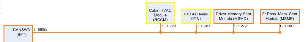
Body CAN Bus - Fault Tolerant - 125 Kbpslink
 |
|---|
The Body Fault Tolerant CAN bus connects the following controllers:
- Remote Climate Control Module (RCCM)
- PTC Heater (PTC)
- Driver Memory Seat Module (MSMD)
- Front Passenger Memory Seat Module (MSMP)
The PTC Heater and RCCM are awake immediately upon receiving power from the HVAC rail. However, the memory seat module is supplied with unswitched 12V power and can become active any time it receives a CAN wake-up message.
The Body Fault Tolerant CAN bus has a ‘T’ on each node. This is because the voltage levels are different from the others. In this architecture, every node adds bus impedance; unlike the other standard CAN buses in which only 2 terminating resistors add impedance to the bus. If either of the CAN wires goes open circuit or shorts to ground, each node’s CAN controllers recognize the fault and convert to single wire CAN on the remaining wire. This provides the fault tolerance.
 |
|---|
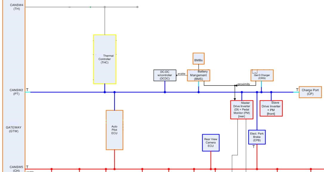
The Powertrain CAN bus connects the following controllers:
- Tesla Gateway (GTW) - T
- Active Safety (TASC)
- Tesla Thermal Controller (THC)
- Battery Management System (BMS)
- Master Charger (CHG)
- Charge Port (CP) - T
- DC-DC Converter (DCDC)
- Master Drive Inverter (DI)
- Slave Drive Inverter (DIS)
- Electric Park Brake (EPB)
The DC-DC Converter, Active Safety Controller and Drive Inverter(s) are awake immediately upon receiving power from the drive rail. However, the BMS, Master Charger, and Charge Port are all supplied with unswitched 12V power and can become active any time they receive a CAN wake-up message (e.g. opening the charge port door). Whether the request comes from pushing the touchscreen button or using the wireless feature on the charge connector, a CAN message is sent to wake all the modules in preparation for charging. The Thermal Controller is awake immediately upon receiving power from the HVAC rail.
Each controller on the schematic is identified by a colored outline. This indicates whether the controller is supplied with unswitched 12V power and wakes on CAN, or wakes when the HVAC, ACC, or Drive rail turns on.
The Powertrain CAN has a ‘T’ on 2 nodes. This indicates the 2 terminating nodes of the bus; each adds 120 ohms to the CAN bus. The terminating nodes are located at the end of each bus, to help with the reflection of the messages. A perfectly terminated CAN bus reads 60 ohms, which is the equivalent resistance of the two 120 ohm terminators in parallel.
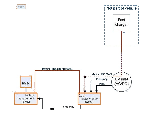
Fast Charge CAN Bus - 125 Kbpslink
 |
|---|
The fast charge CAN connects the following controllers:
- Battery Management System (BMS)
- Master Charger (CHG)
- Fast Charger
The Battery Management (BMS) and Master Charger are supplied with unswitched 12V power and can become active any time they receive a CAN wake-up message (e.g. opening the charge port door).
The fast charge CAN has a ‘T’ on 2 nodes. This indicates the 2 terminating nodes of the bus; each adds 120 ohms to the CAN bus. The terminating nodes are located at the end of each bus, to help with the reflection of the messages. A perfectly terminated CAN bus reads 60 ohms, which is the equivalent resistance of the two 120 ohm terminators in parallel.
Stability Control CAN Buslink
The Stability Control CAN bus connects the following controllers:
- Restraints Controller
- Bosch iBooster (IBST)
- Bosch Brakes & Stability Module (ESP)
The Bosch Airbag Controller (ACU) is powered by the Drive Rail. The Bosch Brakes & Stability Module (ESP) has components powered the Drive Rail and unswitched 12V power. The Bosch iBooster has components power by the ACC Rail and unswitched 12V power.
The Stability Control CAN bus has a ‘T’ on 2 nodes. This indicates the 2 terminating nodes of the bus; each adds 120 ohms to the CAN bus. The terminating nodes are located at the end of each bus, to help with the reflection of the messages. A perfectly terminated CAN bus reads 60 ohms, which is the equivalent resistance of the two 120 ohm terminators in parallel.
Active Safety CAN Buslink
The Active Safety CAN bus connects the ACC Forward Radar ECU to the Active Safety ECU.
All modules on the Active Safety CAN bus are powered by the Drive Rail.
The Active Safety CAN consists of two modules each being a terminator. This indicates the 2 terminating nodes of each bus. Each adds 120 ohms to its respective CAN bus. The terminating nodes are located at the end of each bus, to help with the reflection of the messages. A perfectly terminated CAN bus reads 60 ohms, which is the equivalent resistance of the two 120 ohm terminators in parallel.
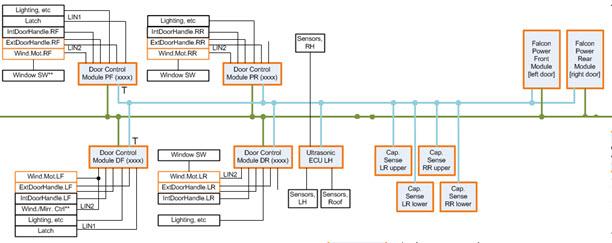
Rear Door Control CAN Buslink
 |
|---|
The Rear Door Control CAN bus connects the following controllers:
- Front Driver Door Control Module (BCFDM)
- Front Passenger Door Control Module (BCFPM)
- Rear Driver Door Control Module (BCRDM)
- Rear Passenger Door Control Module (BCRPM)
- Rear Door Power Front Module - LH
- Rear Door Power Front Module - RH
- Ultrasonic ECU LH
- Capacitive Sensor Module – Upper RR
- Capacitive Sensor Module – Lower RR
- Capacitive Sensor Module – Upper LR
- Capacitive Sensor Module – Lower LR
All controllers on the Rear Door Control CAN Bus have unswitched 12V power, except for the Ultrasonice ECU. The Ultrasonic ECU receives its power from the Rear Driver Door Control Module.
The Rear Door Control CAN bus has a ‘T’ on 2 nodes. This indicates the 2 terminating nodes of the bus; each adds 120 ohms to the CAN bus. The terminating nodes are located at the end of each bus, to help with the reflection of the messages. A perfectly terminated CAN bus reads 60 ohms, which is the equivalent resistance of the two 120 ohm terminators in parallel.
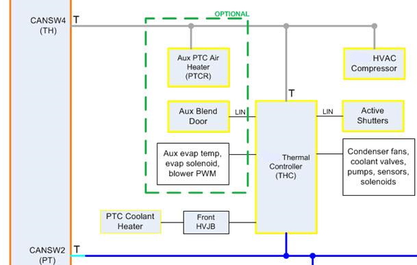
Thermal CAN Bus - 500 Kblink
 |
|---|
The thermal CAN bus connects the following controllers:
- Aux PTC Air Heater (PTCR)
- Tesla Thermal Controller (THC) - T
- Halla HVAC Compressor
- Gateway Module (GTW)) - T
Each controller on the schematic is identified by a colored outline. The outline indicates the controllers power source operation (always powered, ON with Drive Rail, ON with ACC Rail, etc.), along with additional controller wake conditions (e.g. GTW controlled enable).
The modules on the thermal bus are powered on with the HVAC Rail.
The thermal CAN has a ‘T’ on 2 nodes. This indicates the 2 terminating nodes of the bus; each adds 120 ohms to the CAN bus. The terminating nodes are located at the end of each bus, to help with the reflection of the messages. A perfectly terminated CAN bus reads 60 ohms, which is the equivalent resistance of the two 120 ohm terminators in parallel.
Local Interconnect Network (LIN)link
 |
|---|
Model X has 16 LIN buses. They fulfill the following functions:
- SCCM LIN 1 - Steering wheel controls
- GTW LIN 2 - Homelink, 12V Battery & Monitor (IBS)
- GTW LIN 3 – Driver Seat Heater, Passenger Seat Heater, and Rearview Mirror
- GTW LIN 4 - Not Used
- BCFRONT LIN 1 – LF Headlamp, LF Fascia Light
- BCFRONT LIN 2 – RF Headlamp, RF Fascia Light
- BCCEN LIN 1 – RLS
- BCCEN LIN 2 – Windshield Wipers
- BCCEN LIN 3 – Siren / Intrusion Sensor
- BCFDM LIN – Window Switchpack, Window Lifter
- BCFPM LIN – Window Lifter
- BCRDM LIN – Window Lifter
- BCRPM LIN – Window Lifter
- BCREAR LIN 1 – Interior Lighting Module
- THC LIN – Aux Blend Door
- THC LIN (2) – Active Shutters, Air Quality Sensor, Chiller valve
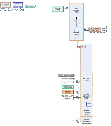
Other Connectionslink
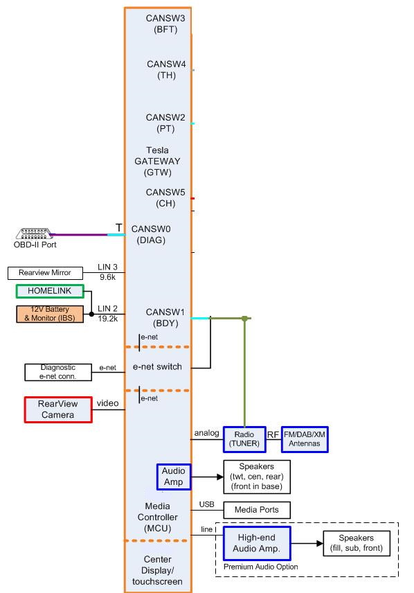 |
|---|
The Tesla media controller section of the GTW has additional connections as detailed in the illustration above.