Second Rowlink
Last updated: November 27, 2023
Overviewlink
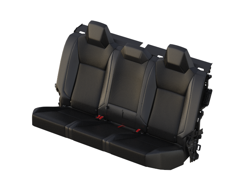
Cybertruck has a standard five-person seating capacity with a driver and passenger seat in the front row. A three-passenger bench seat is mounted to the rear wall with a fold-up seat cushion. The second-row seats do not have ventilation but have seat heating in the outer seats. All seats are designed, engineered, and manufactured by Tesla.
 |
|---|
| Second Row Seats |
The seat sections are referred to as 40% (right-side rear seat), 60% (left-side and middle rear passenger seats), and 20% (middle rear passenger seat).
 |
|---|
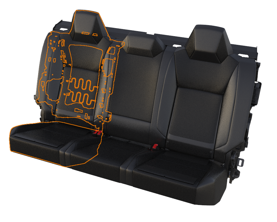
| 40 Percent (or right hand seat) |
Coverslink
Component Descriptionlink
Cybertruck seats are available in black. The vehicle utilizes a mix of Polyurethane (PUR) and Polyvinyl Chloride (PVC). These materials are a leather alternative. The second-row seat does not have ventilation, so there is no need for perforation.
There are removable bolsters between each seating position and on the outer portion of the seats. Removing these allow easy access to components like the Charge Port Electronic Control Unit (ECU) located on the left-hand side of the vehicle.
 |
|---|
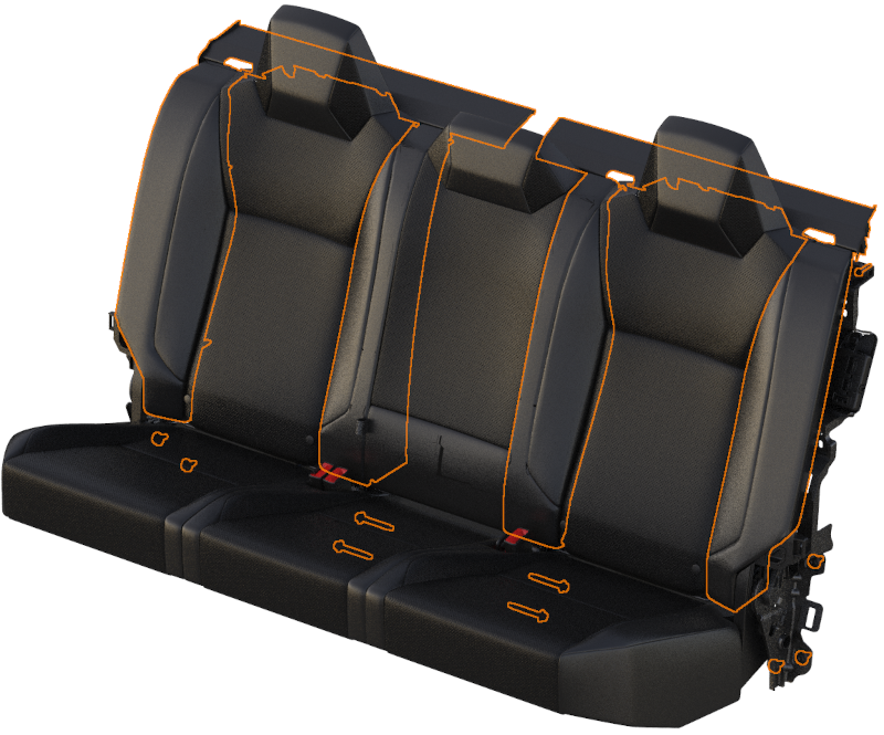
| Second Row Seat Cover |
Theory of Operationlink
Cybertruck second-row seat covers are secured to the foam using a smart clip that attaches within the foam trenches. Once the foam is sandwiched by the cover, it is connected to the upholstery support or pan, ensuring the seat cushion retains its shape before being affixed to the seat frame. Additionally, there is stitch detailing within the seat to aid in shaping it around the foam. A metal seat frame then provides support to the cushion prior to attaching the outermost panel, which is referred to as the underbelly.
Serviceabilitylink
Cleaninglink
Cleaning PUR seats with some conventional cleaners (especially alcohol-based) can cause performance and appearance degradation. Do NOT use products containing bleach (sodium hypochlorite). It is therefore important to clean seats with only approved cleaners. Below is a list of approved cleaners:
- Clorox NON-Bleach Disinfecting Wipes
- Formula 409
- Seventh Generation NON-Bleach Disinfecting Wipes
Foam/Padlink
Component Descriptionlink
The seat foam, also referred to as the seat pad, provides comfort and stability to occupants.
Serviceabilitylink
If the seat foam and covers have not been installed appropriately it can feel or look as if the seat is missing foam or that the foam has collapsed. Because the foam is sandwiched between the cover and upholstery support, it is possible that it could have been misaligned during installation. In some rare cases, the way in which a customer ingresses or egresses from the vehicle can apply pressure on the out most edge of the cover and foam, causing the foam to get caught on the upholstery support and not maintain its full shape. This can be resolved by refitting the cover and foam.
The center lumbar bun slides left to right and locks into place, you will want to remove the left inner bolster in order to gain access to the lumbar bun.
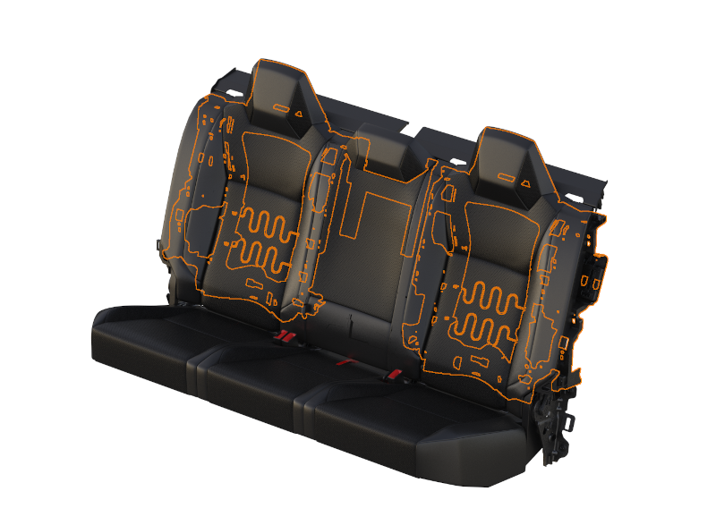
Seat Heatlink
Component Descriptionlink
Cybertruck second row has heating elements in the left and right seat positions, but not in the center seat.
 |
|---|
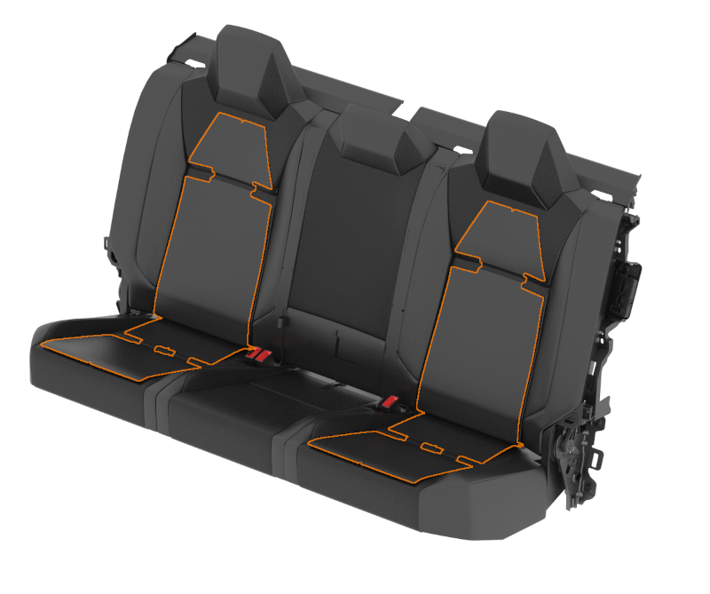
| Second Row Seat Heat |
The seat heater is made up of the following components:
- High side driver
- Pulse width modulation (PWM)
- Negative temperature coefficient (NTC) thermistors
- Resistive pad
The heating element, or resistive pad, is located only in the center panels of the seat back and seat cushion, the heating element is not located in the side bolsters.
Theory of Operationlink
There are 3 heating temperature targets for the seats (low, medium, and high). Target temperatures as read by the NTC in the cushion for both the cushion and the backrest are:
- Low (Setting 1): 28C or 82F
- Medium (Setting 2): 44C or 111F
- High (Setting 3): 60C or 140F
Be mindful that the temperatures read by the NTC will differ than the temperature on the surface of the trim.
The seat heaters utilize PWM at 1Hz in order to reach the desired target temperature. This means pulsing the voltage at a controlled frequency. The duty cycle (width of the pulses) will be increased if the temperature read by the NTC is below the target temperature, the duty cycle can be increased all the way up to 100%, providing up to 48V. When the temperature read by the NTC is higher than the target temperature, the duty cycle can be decreased all the way to 0% providing no voltage. Due to this PWM, the voltage at the seat heater is constantly changing and varies due to ambient temperature and heat setting level.
Current travels through the resistive pad generating the heat. This resistance remains constant with a functioning seat heater.
The NTC is located only in the seat cushion, not the seat back. It is connected to 3.3V through a resistor on the body controller. As the temperature of the seat increases, the resistance on the NTC lowers and the voltage read at the controller goes down. If the thermistor is disconnected, the voltmeter will read 3.3V or 0V depending on where the disconnect occurs. At around room temperature, the voltage at the NTC should be around 3.6V.
Communicationlink
The seat heaters are connected to VCREAR, and VCREAR communicates the seat heater status on Etherloop.
Serviceabilitylink
The seat heater resistive pad is integrated into the seat cover and is therefore not serviceable.
The temperature felt at the surface of the seat, depends on an occupant sitting in the seat. Compressing the foam and trim with an occupant sitting in the seat allows for the occupant to fully feel the temperature provided by the seat. Factors such as a heat-soaked interior, body heat from someone sitting in the seat, direct sunlight, and ambient air temperatures can play a big role on the temperature readings at the surface of the seat cover.
Occupancy Sensinglink
Component Descriptionlink
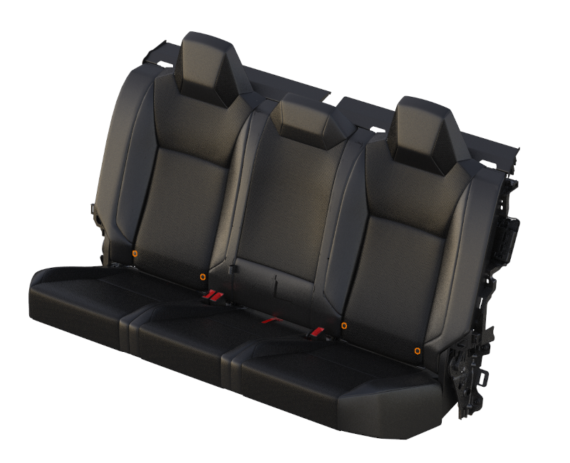
Each seat in the second row contains an occupancy sensor, resistive pad, also referred to as the seat belt reminder (SBR). The occupancy sensors are located in the seat cushion. The occupancy sensors are switches distributed throughout the cushion connected in both parallel and series.
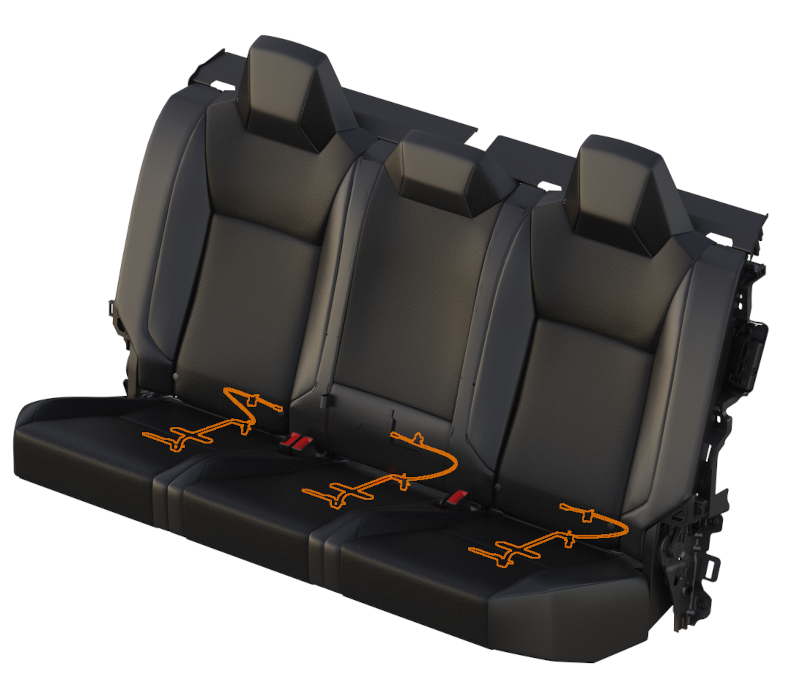 |
|---|
| Restive Pad (x3) |
Theory of Operationlink
Occupancy sensing for the second row is connected to VCREAR. VCREAR then communicates the occupancy sensor status on Etherloop. The sensor itself is a simple resistive pad that can be tested with a multimeter. Occupied, the resistance should read 1kOhm. Unoccupied, the resistance should read 11kOhm.
Serviceabilitylink
Occupant sensors distributed throughout the cushion help prevent situations where small items might trigger the seat belt reminder indicator. At the time of publishing this document, the resistive pad, or seat belt reminder, located in the second-row cushion, is not a serviceable component. This is due to the infrequency of which this part needs to be replaced as well as current production capability.
Framelink
Component Descriptionlink
The second row gets its structure from the seatback substrates that are mounted to the rear wall, the main frame, and the cushion frame.
Theory of Operationlink
The backrest substrates allow for the seat to have shape and mount to the rear wall. The seat foam and covers mount to these substrates. On the left and right seating positions the substrate contains lumbar springs to support an occupant. There is also a headrest frame to give shape to the foam and trim of the headrest.
 |
|---|
| Backrest Substrate |
The main frame, located lower on the seat back, provides the support off the rear wall and aids in the stowing and use position of the seat cushion.
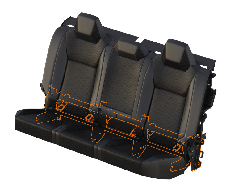 |
|---|
| Main Support Frame |
The cushion frame provides structure and support for occupants in the use position. The frame itself bolts to the stantons connected to the battery pack.
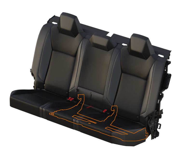 |
|---|
| 60% Cushion Frame |
The second-row seat is designed to allow for 3 child seats.
Armrestlink
Component Descriptionlink
The second row is equipped with an armrest at the center seating position. In the deployed position there are 2 cup holders.
Theory of Operationlink
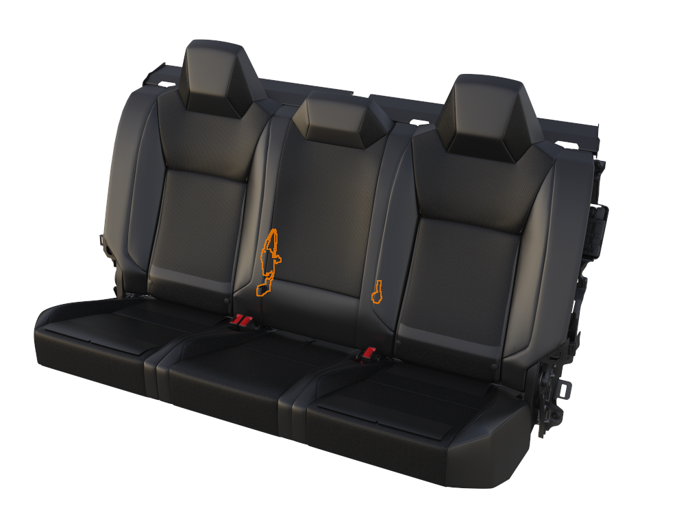
The armrest has a manual release strap located at the lumbar bun. This release pulls on the armrest latch located on the RH side of the center seat. On the LH side of the center seat is a spring that helps aid in the deploying of the arm rest.
 |
|---|
| Armrest Latch, Release strap and spring |
Cushion Stowlink
Feature Descriptionlink
The second-row cushion can be stowed in the upright position in order to give more storage in the second row. When in the use position, the cushion sits atop the rear wall lower stantons that are covered by the rear wall lower carpet.
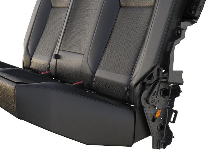
Theory of Operationlink
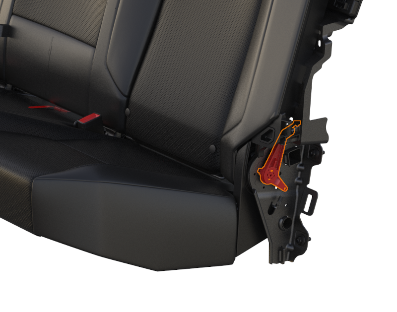
There are two positions that the second-row seat cushion can be locked into, the cushion folded up or the cushion deployed in use position. A recliner mechanism is welded on both outboard sides of the frame, between the main seatback frame and the cushion frame in order to allow for this feature.
 |
|---|
| Left Hand Recliner |
The recliner cannot lock in between these two positions. There are also stopper and bump stops to keep the cushion in its locked position.
 |
|---|
| Bump Stops |
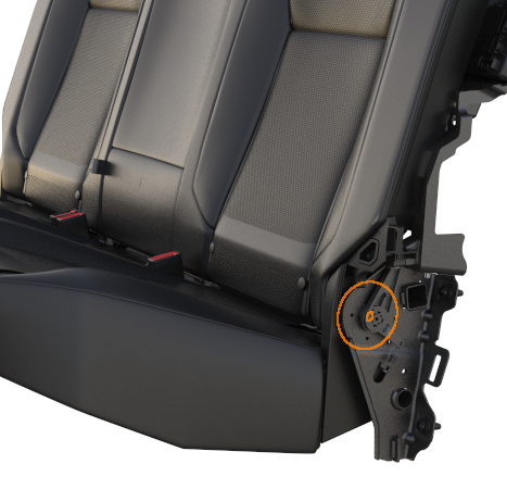
A plastic release lever is snapped onto the recliner spline. This lever is utilized to release the seat cushion from either of the locked positions. It must be used to release from the stowed position or to be released from the use position.
 |
|---|
| Release Lever |
There is a release lever spring that works against the user pulling the release lever. This is intended to prevent the lever from moving during driving scenarios; it also helps with skip locking.
 |
|---|
| Release Lever Spring |
Within the recliner mechanism is a clock spring that aids in kicking the cushion up to get it from the use position to the stowed position. This spring is only a lift assist to provide assistance in stowing the cushion; the user must push the cushion the rest of the way to lock it into place.
This same clock spring prevents the cushion from slamming down onto the rear floor when going from stowed to use position.
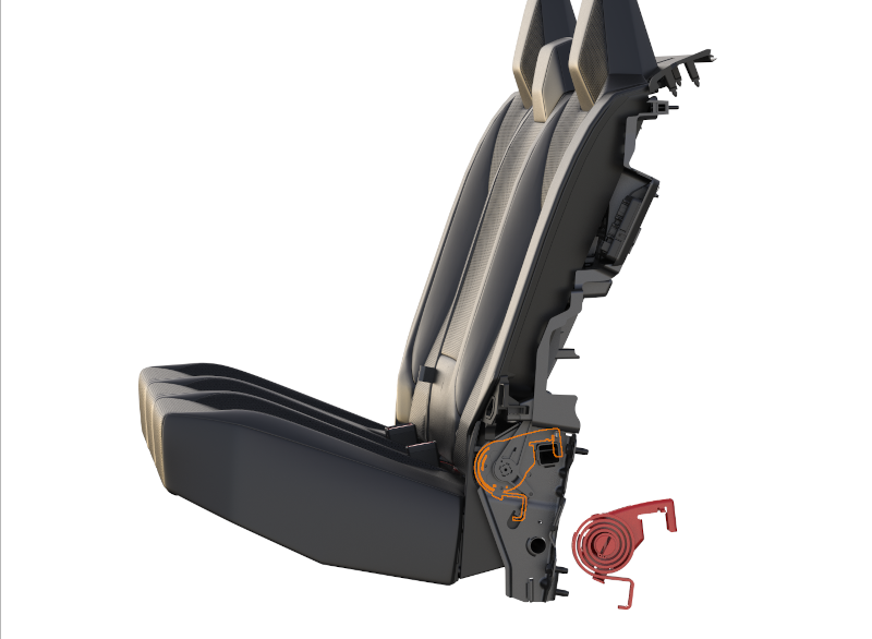 |
|---|
| Clockspring |
Serviceabilitylink
It is possible when installing the bolsters or lumbar bun that the release straps may get stuck behind the bolsters, be sure to leave straps out when installing bolsters.
In order to gain access to the recliner mechanism, the C-Pillar trim must come off.