Connectivitylink
Last updated: January 19, 2024
Overviewlink
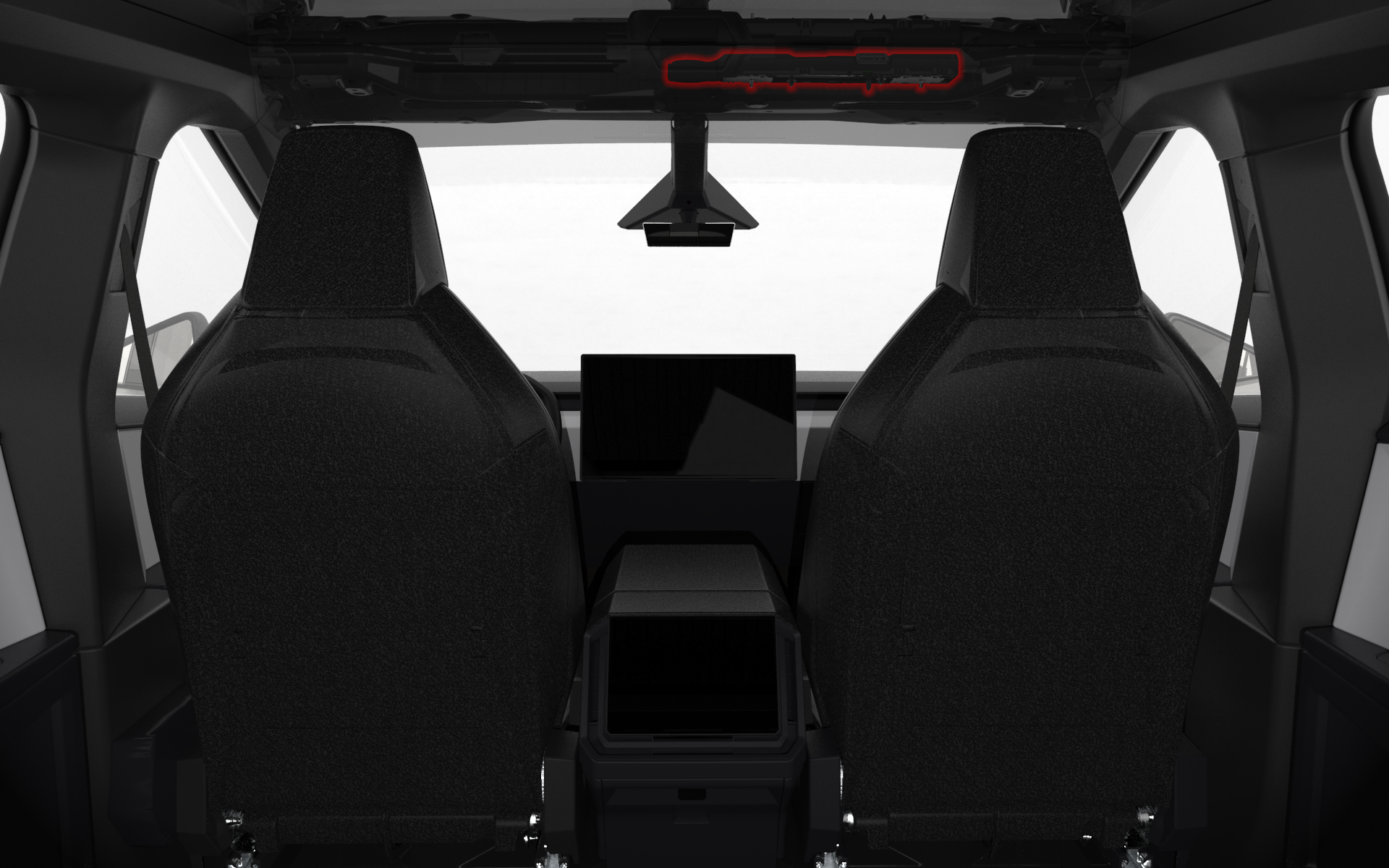
Cybertruck connects to the cellular network, Wi-Fi network, and external Bluetooth devices through the Telematics Control Unit (TCU). The TCU replaces the functions of the connectivity card (or modem card), the Wi-Fi and Bluetooth module, and their antennas within a single assembly. It is located in the front headliner of the Cybertruck.
 |
|---|
| TCU Location |
 |
|---|
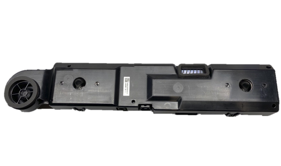
| Telematics Control Unit (TCU) |
System Architecturelink
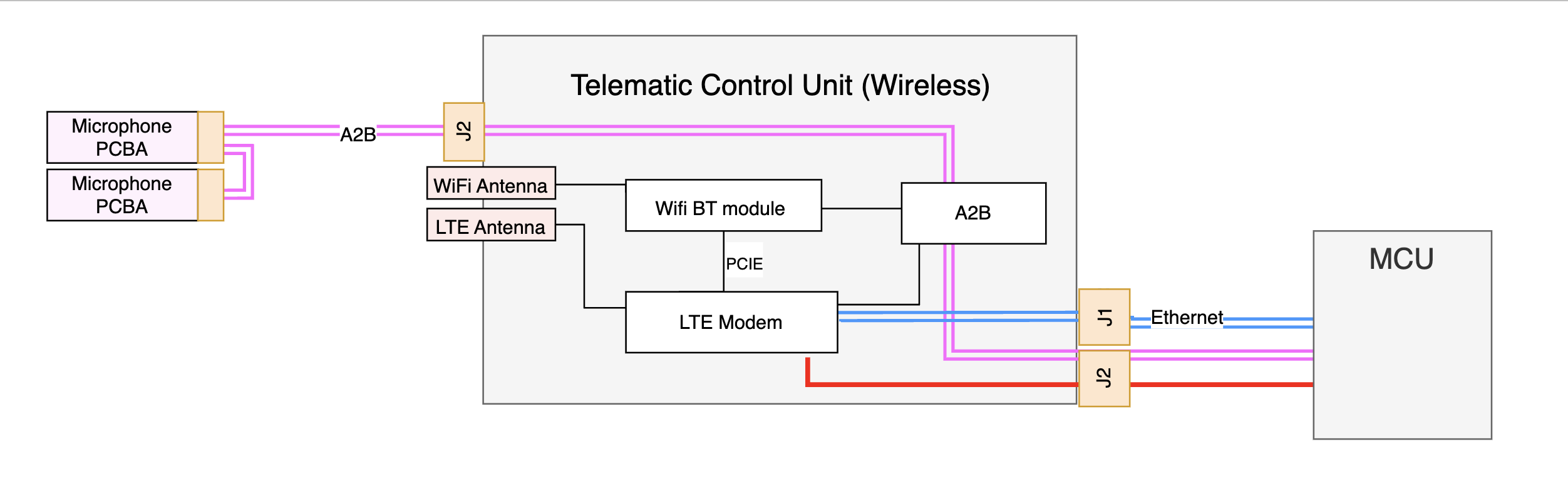
The TCU contains an Automotive LTE module, a Wi-Fi and Bluetooth module, an Ethernet Physical Layer (PHY) chip and an A2B transceiver. It is powered by the Media Control Unit (MCU) through the A2B harness. TCU is also connected to the infotainment computer through an Ethernet harness which carries all the data over Ethernet protocol. The harness is used for the data traffic between the Infotainment main board and the Cellular module, Wi-Fi, and Bluetooth module. The LTE and Wi-Fi antennas are located within the TCU.
 |
|---|
| TCU Block Diagram |
 |
|---|
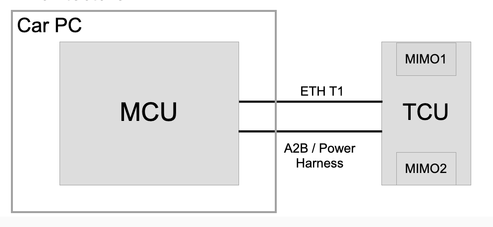
| TCU Connectivity Architecture |
TCU Components Breakdownlink
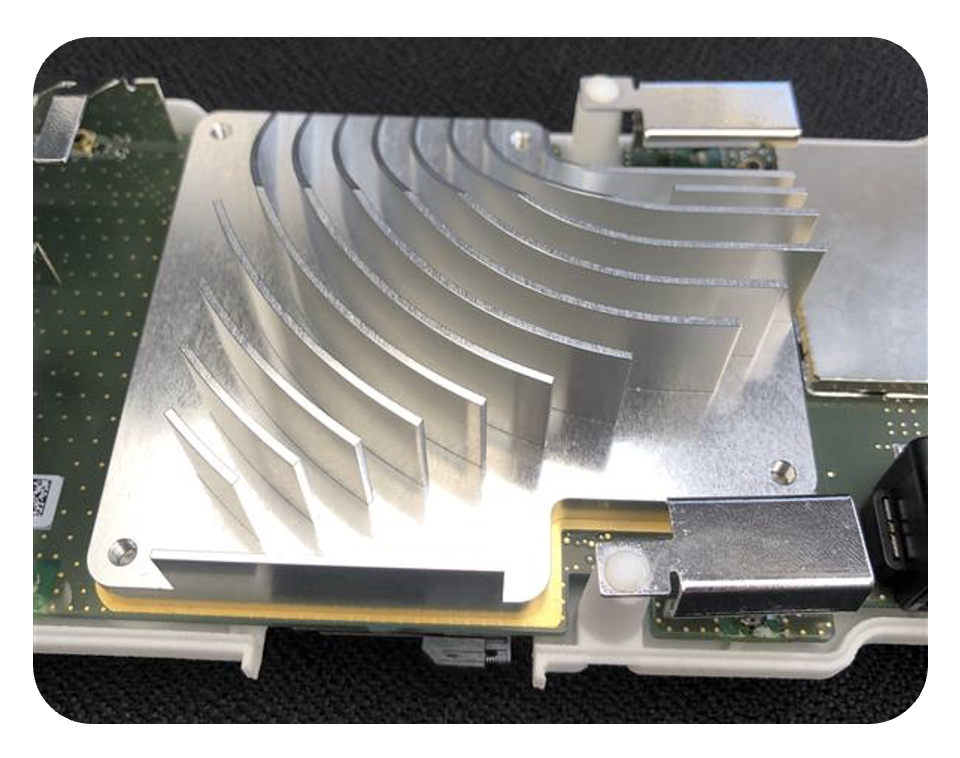
 |
|---|
| TCU PCB |
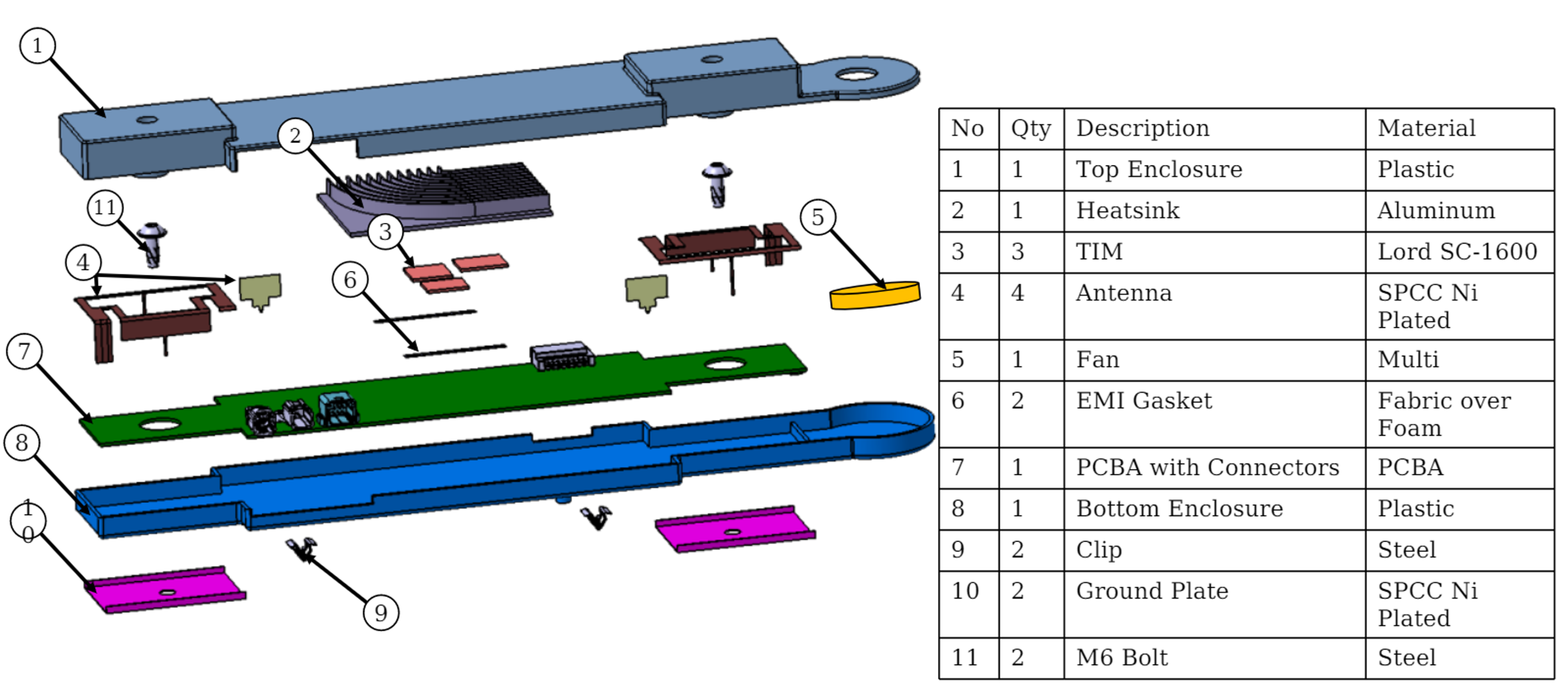
Mechanicallink
The TCU mainly consists of top and bottom enclosures, a fan, a cast aluminum heat sink, and a printed circuit board assembly (PCBA). The fan housing is integrated into the TCU enclosure. The antenna is grounded to body-in-white through the ground plate. The heat sink is also used for shielding. The TCU only has two connectors. One is a 2-pin connector for the Ethernet harness. The other is an 8-pin connector for A2B bus, power, and ground.
 |
|---|
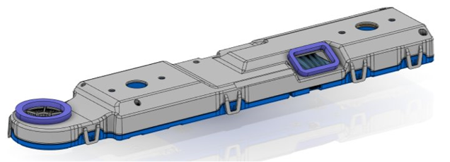
| TCU Assembly |
 |
|---|
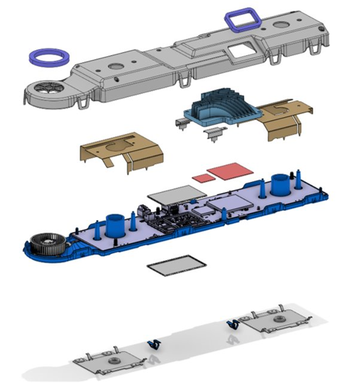
| TCU Internal |
 |
|---|
| TCU Components |
Cellular modulelink
A single worldwide LTE module variant is used in the TCU.
The TCU runs its own firmware package, and the package can be updated through the car computer updater and the TCU updater. The car computer updater communicates with the remote Tesla firmware server and controls the TCU updater, which controls the firmware update procedure for the TCU.
The Cellular module is connected to the Wi-Fi and Bluetooth module through Peripheral Component Interconnect Express (PCIe) and Universal Asynchronous Receiver-Transmitter (UART). It is also connected to the TCU Ethernet PHY, which connects to the Infotainment Ethernet switch in the car computer. Data traffic flows between the car computer and the Wi-Fi and Bluetooth module through the Cellular module and the Infotainment Ethernet switch.
SIM Cardlink
A Subscriber Identity Module (SIM) card is an integrated circuit intended to securely store the International Mobile Subscriber Identity (IMSI) number and its related key, which are used to identify and authenticate subscribers on mobile telephony devices. Every TCU has an embedded SIM (eSIM) chip and an external 2FF SIM card slot. The SIM selection is controlled by the Cellular module, and it is configured by the main SoC.
An eSIM chip can store more than one profile, and the eSIM profiles need to switch according to the carrier of the region.
The external SIM reader slot is located on the bottom of the TCU PCBA.
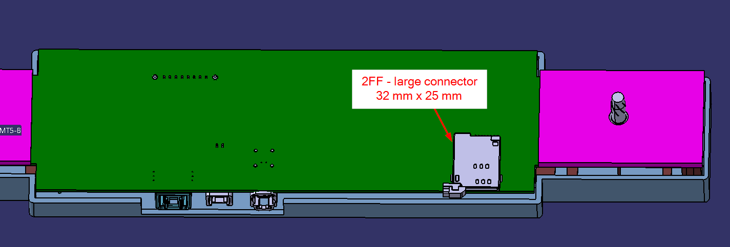 |
|---|
| TCU External SIM Reader Location |
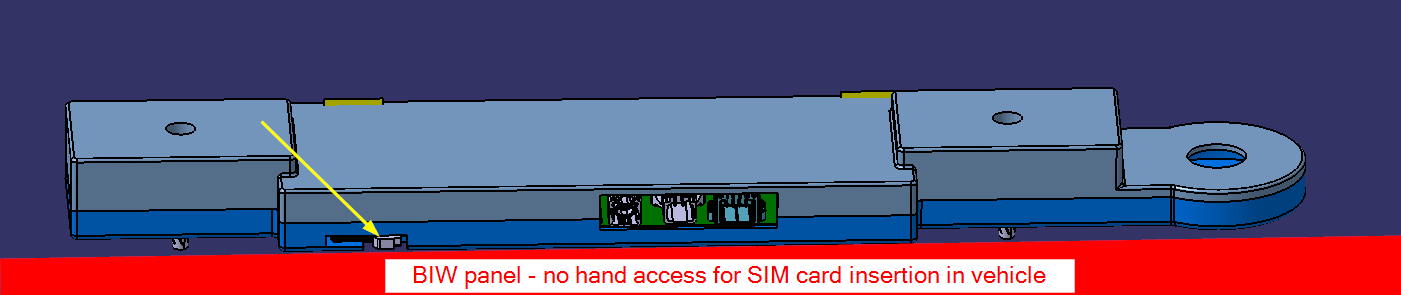 |
|---|
| TCU External SIM Card Insertion |
Wi-Fi and Bluetooth Modulelink
The data traffic flows from the Wi-Fi and Bluetooth module to the Cellular module, and then to the main SoC on the car computer. Specifically, the Wi-Fi data flows through PCIe to the Cellular module. The Bluetooth data and control traffic flow between Bluetooth chipset and Cellular module through UART. The Cellular module and Infotainment computer exchange this data over Ethernet.
The Bluetooth voice traffic passes over the I2S interface to the A2B transceiver to the audio digital signal processor (ADSP) upstream in the car computer main SoC, or downstream to microphones.
Note
TCU does not exchange the voice data directly with the microphones. All the downlink and uplink voice data is exchanged between Bluetooth module and ADSP over A2B.
Automotive Audio Bus (A2B) Chipsetlink
The same A2B transceiver is used in the TCU as the one used in the infotainment board. The A2B chipset in the TCU is part of the A2B daisy chain. The A2B chipset in the infotainment board is the A2B primary, and the one in the TCU is the A2B secondary. The upstream of the daisy chain from the TCU is the Audio Digital Signal Processor (ADSP) on infotainment main board and the downstream are the microphones.
A2B is also used for module level control signaling between infotainment board and TCU. Infotainment computer can use this interface to reboot the TCU, read and write GPIO connected to Cellular module, and determine which NAND (Primary or Recovery) to boot the TCU from.
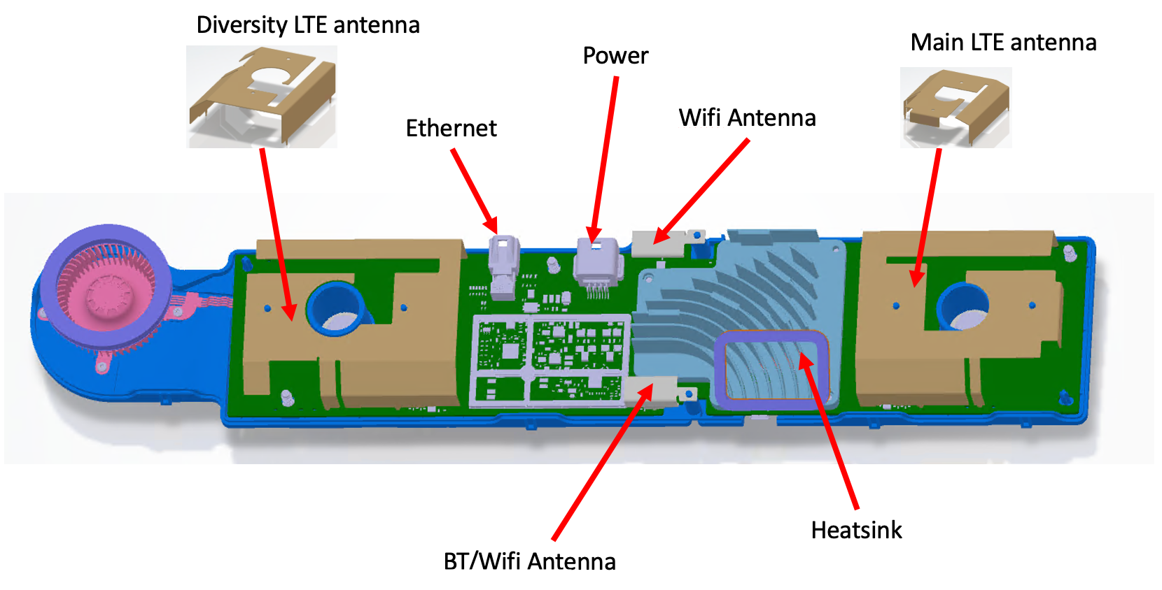
Antennaslink
The Multiple Input Multiple Output (MIMO) antennas in the TCU are integrated into the TCU PCBA and are not individually serviceable.
- Two LTE antennas function as a 2x2 MIMO pair.
- One is the main LTE antenna, and the other one is the diversity LTE antenna. Diversity reception reduces the probability of occurrence of communication failures caused by fades by combining several copies of the same message received over different antennas.
- One dedicated Wi-Fi antenna supports the 2.4GHz and 5GHz Wi-Fi MIMO.
- One switched antenna supports either the 2.4GHz Bluetooth or 2.4GHz and 5GHz Wi-Fi MIMO.
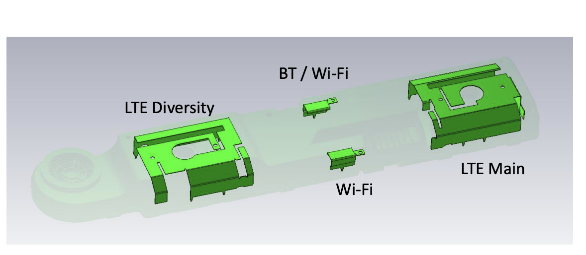 |
|---|
| Antenna Locations |
Interfaceslink
The TCU power is supplied by the Infotainment main board through the same socket of the A2B bus. In addition to the functional modules, there is also a GPIO extender chip in the TCU to control the TCU property. The GPIO expander chip can be configured by the A2B primary through the A2B bus. It is used to reboot the Cellular module, read and write the GPIOs, and determine which NAND (primary or recovery) to boot the Cellular module from. This serves as a control interface between Infotainment board and TCU.
There is an Ethernet PHY chip on the TCU board, which is connected to the Ethernet switch through the MCU PHY, both located on the Infotainment board.
Cooling Systemlink
The TCU is located in the front headliner where high ambient temperature is expected. As a result, multiple cooling methods are used:
- Dispensable Thermal Interface Material (TIM).
- Cast Aluminum heat sink is used for LTE Cellular module and Wi-Fi and Bluetooth module.
- Fan / blower is controlled by the Cellular module.
The TCU has a fan (blower) that is controlled by the Cellular module. The airflow from the fan passes through the heatsink to cool the chipset. The fan speed is controlled by the following parameters:
- Temperature of LTE and Wi-Fi and Bluetooth modules.
- There is a temperature sensor within the TCU.
- Occupancy state of vehicle.
- Lower duty cycles run when there are occupants inside the vehicle, and the HVAC is running at a lower setting due to the given proximity of the fan to the driver's and passenger's ear.
- State of the HVAC blower.
For low ambient temperature, the TCU module is expected to operate without turning on the fan. The TCU periodically wakes up, checks the temperature, and goes into sleep. If the temperature exceeds the threshold, then the fan will be turned on without waking up the MCU.
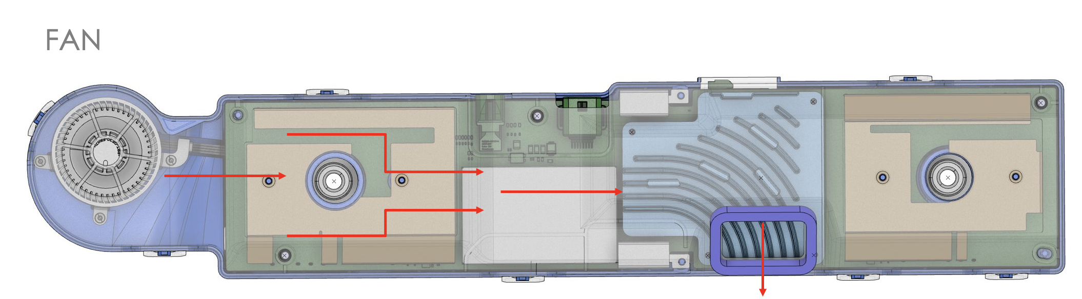 |
|---|
| TCU Fan Airflow |
 |
|---|
| TCU Heatsink |
Cellular Connectionlink
The Cellular module of TCU is responsible for the cellular communication of the TCU. The control traffic of the module is through the A2B bus and the data traffic is through the Ethernet. - Low-level firmware processes run in the Cellular module and communicate with the cellular tower of the carrier. - The cellular tower will register or unregister the module depending on the information provided by the module. The information includes the module's IMEI(International Mobile Equipment Identity), SIM card identification, and the technology it supports. - The cellular carrier may provide limited service (Roaming) if the SIM card ID does not match its local market region. - High-level firmware processes manage the network connectivity.
The Cellular module only supports LTE (or 4G) cellular standard or below.
Toolbox users with a physical connection to the vehicle are able to power cycle the Cellular module and restart the software processes without rebooting the car computer by running the ODIN task PROC_ICE_X_SET-MODEM-POWER-STATE with argument 'cycle'. Toolbox cannot access the low level cellular software in the TCU directly.
Wi-Fi Connectionlink
The Wi-Fi software stack runs on the Wi-Fi module of the TCU. The data traffic goes from the Wi-Fi module to the Cellular module and then to the Ethernet. The function of the Wi-Fi stack includes the following:
- Loading the Wi-Fi kernel module.
- Setting up the wlan interface on the TCU.
- Enabling "wpa_supplicant" so the TCU can resolve authentication and connect to a wireless access point.
- Running "dhcp" to get an IP address from the access point once connected.
- Running "dnsmasq" so the MCU can connect to TCU.
Connection management processes run on the main SoC to control the Wi-Fi module and includes the following:
- Health check for connectivity.
- Knowledge about Wi-Fi power state.
- Control the Wi-Fi module power state and interfaces with TCU over a Transmission Control Protocol (TCP) socket.
Toolbox users with physical connection to the vehicle are able to power cycle the Wi-Fi and Bluetooth module and restart the main SoC software processes without rebooting the car computer by running the ODIN task PROC_ICE_X_SET-MODEM-POWER-STATE with argument 'cycle'. Toolbox cannot access the Wi-Fi stack software in TCU directly.
Bluetooth Connectionlink
Bluetooth media audio and control signals are sent via Ethernet from the TCU to the MCU while Bluetooth telephony call audio are sent via A2B from and to the MCU.
Bluetooth A2DP audio is communicated to the MCU using the Ethernet path and is used for streaming music from a connected device. The Hands-Free Protocol (HFP) audio is used for hands-free calls and follows the I2S path from the Bluetooth module to the MCU over A2B. This will be running at WideBand Speech or NarrowBand Speech, which uses 16kHz or 8kHz respectively.
Toolbox users with physical connection are able to power cycle the Wi-Fi and Bluetooth chip and restart the software processes without rebooting the car computer by running the ODIN task PROC_ICE_X_SET-MODEM-POWER-STATE with argument 'cycle'.
Firmware Updatelink
The TCU runs its own firmware and has its own flash memory to store the package. The TCU boots from the flash memory in the unit, and it runs its own updater software. The TCU updater will update the firmware package in the flash memory when it receives the installation command from the main infotainment updater.
Diagnosticslink
The status of the Cellular module will be relayed to the main SoC through the Ethernet connection. In addition, the Cellular module and the Wi-Fi and Bluetooth module health check ODIN task can be run to verify the TCU hardware and firmware is running properly.
The Service Mode Connectivity panel shows the status of both the cellular and Wi-Fi connection. It also shows the ODIN task which is available for the hardware health check.
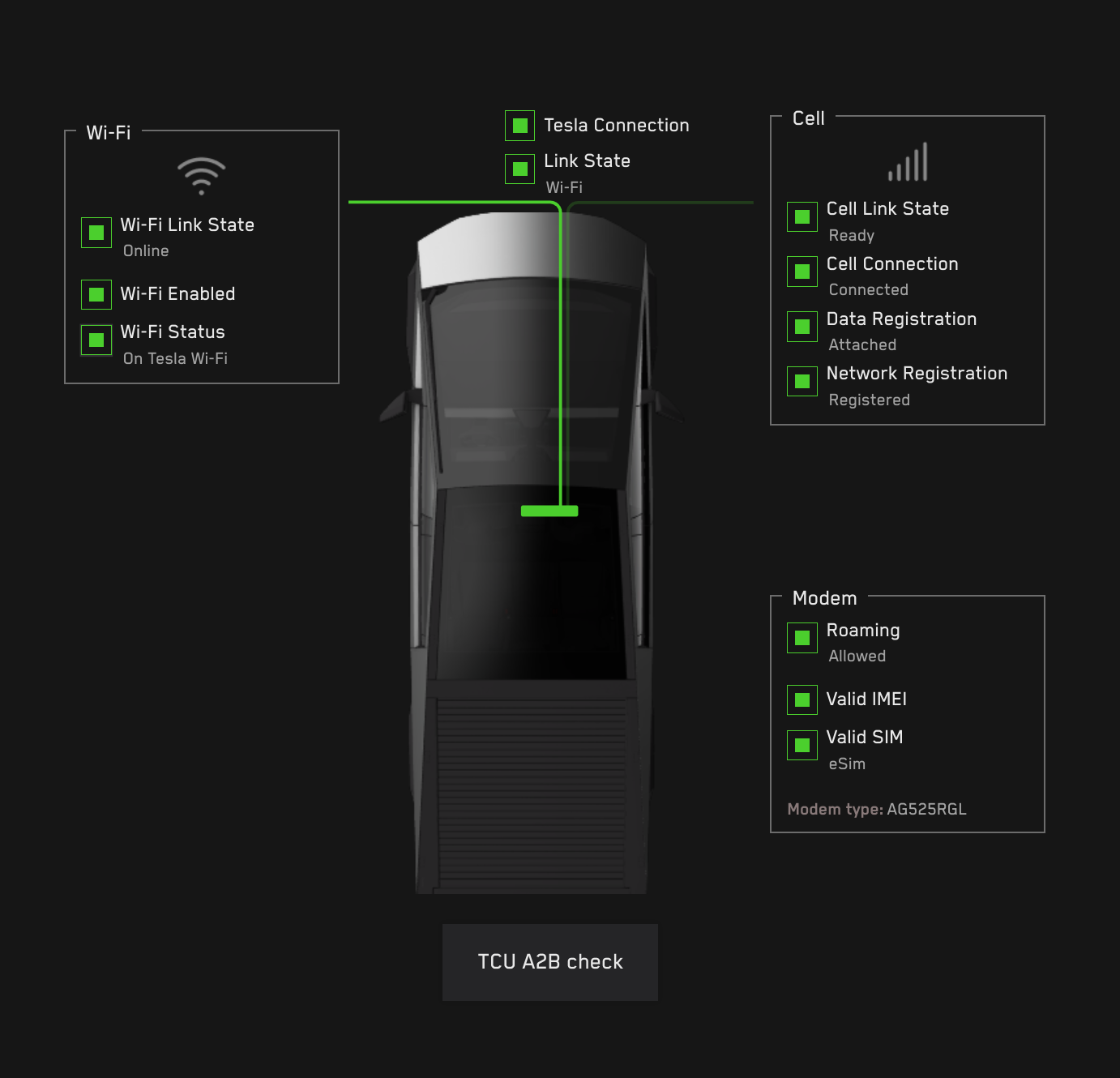 |
|---|
| Service Mode Connectivity Panel shows the TCU is connected to Tesla network with Wifi connection |
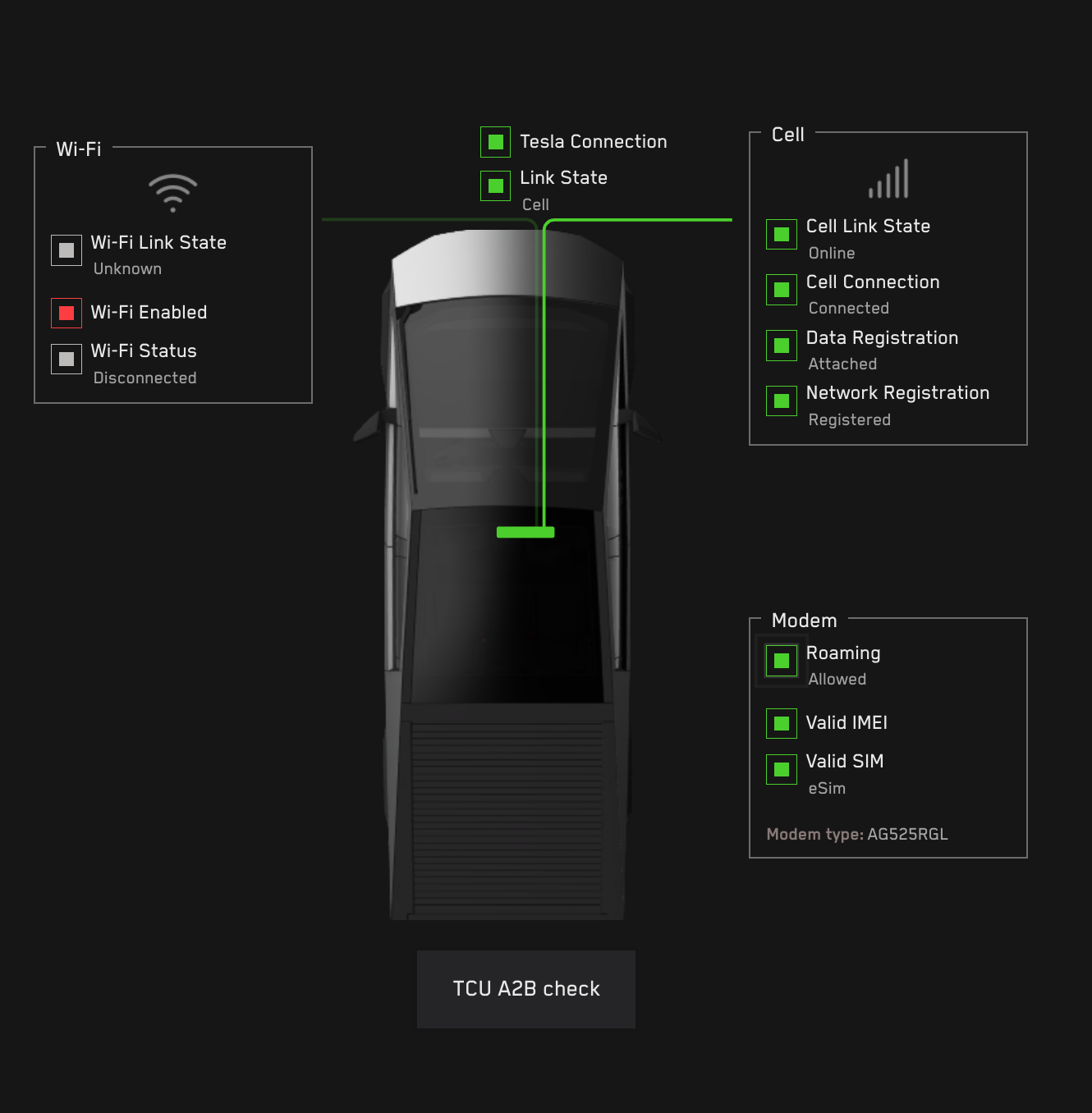 |
|---|
| Service Mode Connectivity Panel shows the TCU is connected to Tesla network with Cellular network when Wifi is disable |
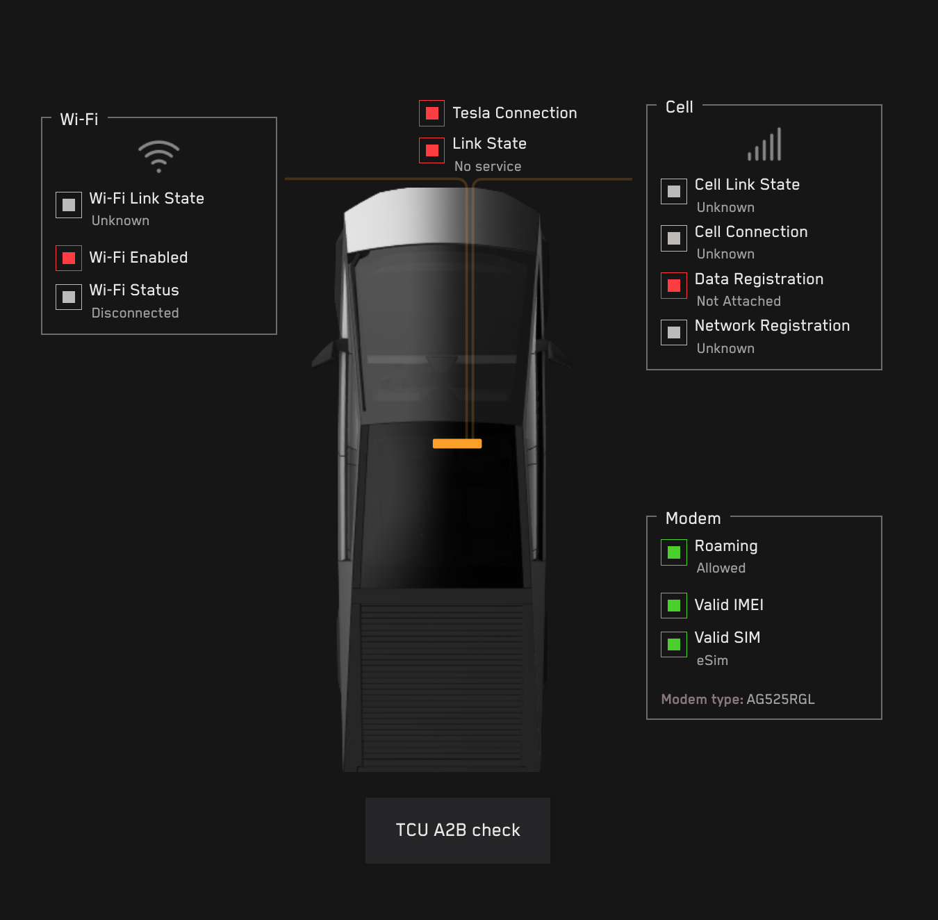 |
|---|
| Service Mode Connectivity Panel shows the TCU is not connected to Tesla network when its power supply is off |
Serviceabilitylink
The components of the TCU are not replaceable, except for the external SIM Card. The TCU itself can be replaced.