Safety and Restraints Systemlink
Last updated: October 20, 2023
Overviewlink
Component Locationlink
 |
|---|
| 1. Passenger airbag 2. Seat belt retractor pretensioner - RH 3. Lap belt pretensioner – RH 4. Side airbag – RH seat 5. Seat belt buckle – RH 6. Side curtain airbag – RH 7. Seat belt pretensioner – 2nd Row 8. Seat buckle – 2nd Row 9. Side airbag – LH seat 10. Seat belt retractor pretensioner – LH 11. Lap belt pretensioner – LH 12. Side curtain airbag – LH 13. Seat belt buckle – LH 14. Driver airbag 15. Knee airbag – LH 16. Knee airbag – RH |
| North America |
 |
|---|
| 1. Passenger airbag 2. Seat belt retractor pretensioner - RH 3. Lap belt pretensioner – RH 4. Side airbag – RH seat 5. Seat belt buckle – RH 6. Side curtain airbag – RH 7. Seat belt pretensioner – 2nd Row 8. Seat buckle – 2nd Row 9. Side airbag – LH seat 10. Seat belt retractor pretensioner – LH 11. Lap belt pretensioner – LH 12. Side curtain airbag – LH 13. Seat belt buckle – LH 14. Driver airbag 15. Pedestrian Protection - actuator 16. Pedestrian Protection - pressure sensor |
| Europe and China |
 |
|---|
| 1. Passenger airbag 2. Seat belt retractor pretensioner - RH 3. Lap belt pretensioner – RH 4. Side airbag – RH seat 5. Seat belt buckle – RH 6. Side curtain airbag – RH 7. Seat belt pretensioner – 2nd Row 8. Seat buckle – 2nd Row 9. Side airbag – LH seat 10. Seat belt retractor pretensioner – LH 11. Lap belt pretensioner – LH 12. Side curtain airbag – LH 13. Seat belt buckle – LH 14. Driver airbag 15. Pedestrian Protection - actuator |
| All other markets |
Sensor Locationlink
 |
|---|
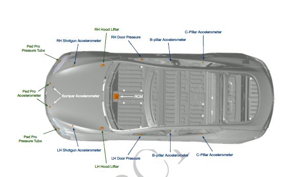 |
| The above photos indicate the locations of the sensors used in the safety and restraints system |
| Accelerometers and sensors |
The following sensors are only applicable to Model S vehicles produced after February 2019:
- shotgun accelerometers
- bumper accelerometers
- pedpro fascia accelerometers
Generallink
Model S is equipped with a Tesla Supplementary Restraint System (TSRS). The system is comprised of the following components:
- Passive safety restraint control module (PSRCM)
- Pyrotechnic fuse
- Driver and passenger dual-stage front airbags
- Driver and passenger knee airbags (North America ONLY)
- Driver and passenger seat side (pelvis/torso) airbags
- First and second row side curtain airbags
- Collapsible steering column
- Driver and passenger seat belt pretensioners
- Multiple impact sensors
- Occupant classification system (OCS) (North America Only)
- Seat belt reminder (SBR) switches
- Pedestrian Protection Program (Europe (EMEA) and Asia (APAC) Only)
The TSRS is designed to work in conjunction with the seat belts. These devices supplement, but do not replace, the protection afforded by the seat belts. Seat belts are proven to be the single most effective safety device in a vehicle, and should always be worn. Properly worn seat belts also ensure that the occupant is seated in the optimum position to benefit from the full effectiveness of the airbags and seat belt pretensioners.
The first row safety restraints feature shoulder and lap belt pyrotechnic pretensioners, dual-stage front airbags, seat side airbags, and knee bolster airbags to protect each occupant. In North American market cars, the passenger seat has an advanced occupant classification system (OCS) that can adapt or inhibit airbag deployment based on occupant size or detection of a child seat (among other parameters, such as an empty seat). The first and outboard second row occupants are protected by side curtain airbags that deploy from the roof rails. The collapsible steering column plays a role in occupant safety as well, by absorbing the energy of the driver’s upper body during a frontal collision.
In the event of a collision, the pyrotechnic fuse deploys to isolate high voltage to the HV Battery. All high voltage is therefore removed from all cabling, the DC/DC converter, the HV junction box, the cabin HVAC system, etc.
The TSRS is designed to deploy in select moderate-to-severe front, side, and rear impacts, as well as rollovers. When the PSRCM detects an impact that warrants deployment, the seat belt pretensioners and pyrotechnic fuse are triggered. Whether any airbags are deployed, and which ones are deployed, depends on the type and severity of the impact. Seat belt pretensioners will not deploy if a seat belt is unbuckled.
Although the airbags and pretensioners are designed to be triggered electrically, they are pyrotechnic devices and could deploy unexpectedly— even when not connected to an electrical source— if proper transport, storage, and handling methods are not followed. Always follow Service Manual procedures when diagnosing or repairing the TSRS. Only use Tesla-approved equipment to intentionally deploy a pyrotechnic device for disposal purposes.
Warning
Accidental deployment can cause damage and personal injury. Always refer to the Owner Information for correct use of the TSRS and seat belt systems, and to the Service Manual for correct fitment, repair, and disposal of system components.
Component Descriptionslink
Passive Safety Restraint Control Module (PSRCM)link
 |
|---|
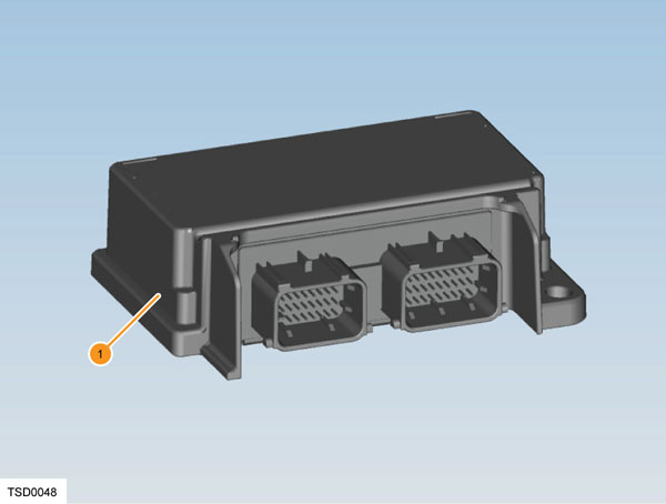
| 1. PSRCM |
| Passive Safety Restraint Control Module (PSRCM) |
The TSRS is controlled by the Passive Safety Restraint Control Module (PSRCM), which includes fault detection and warning circuits. If a fault is detected, an indicator light in the instrument panel notifies the driver. Diagnostic Trouble Codes (DTCs) are also retrievable using Toolbox.
The PSRCM is calibrated specifically to the vehicle model. It contains accelerometers to measure forces acting on the vehicle, and circuits for monitoring the resistance, and therefore condition, of all deployment loops and pyrotechnic devices. It is the primary device that commands the deployment of all TSRS components.
In the event of a collision, the PSRCM compares the signals from the crash and pressure sensors to pre-calibrated values stored in memory. When the generated signals exceed the pre-calibrated values, the PSRCM directs current through the appropriate deployment loops to deploy the airbags, pretensioners, and pyrotechnic fuse as necessary, depending on the severity of the impact. The PSRCM records certain aspects of the event data when a deployment occurs and displays the AIRBAG indicator located in the instrument panel.
When deployment occurs, the PSRCM sends a collision detection CAN message to the body controller to switch on the interior and hazard lights and unlock all doors and the trunk.
The PSRCM performs continuous diagnostic monitoring of the TSRS system electrical components and circuitry when the vehicle is turned on. A safing sensor within the module provides an electro-mechanical switch as a backup to the accelerometer circuit.
If the PSRCM detects a malfunction, a DTC is stored and the PSRCM requests the instrument cluster to display the AIRBAG indicator, notifying the driver that a malfunction exists. If positive voltage is lost during a collision, the PSRCM maintains a volt reserve loop for airbag deployment.
Delphi is the manufacturer of the PSRCM in vehicles prior to February 2019. Use SDM Node.
Bosch is the manufacturer of the PSCRM (RCM2) in vehicles post February 2019. Use RCM Node.
The Bosch RCM is oriented differently in the vehicle than the Delphi PSRCM, with the Bosch RCM, the connector cavities face towards the right hand side of the vehicle.
Pyrotechnic Fuselink
 |
|---|
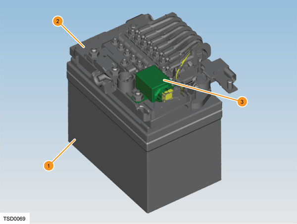
| 1. 12 volt battery 2. Battery fusebox 3. Pyrotechnic fuse F93 |
| Pyrotechnic Fuse |
The pyrotechnic fuse (F93) is located on the battery fusebox. The PSRCM fires the fuse anytime the airbags and/or pretensioners deploy. This isolates high voltage to the HV Battery, which makes the vehicle safe for the occupants and emergency responders if the high voltage system is compromised by collision damage. The pyrotechnic fuse might deploy without airbag deployment.
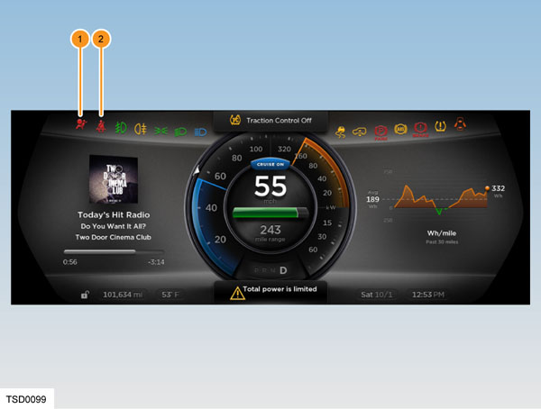
Airbag Indicator Lightlink
 |
|---|
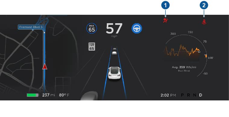
| 1. Airbag indicator light 2. Front seat belt indicator light |
| Airbag Indicator Light |
The airbag indicator light, located in the instrument cluster, is used to notify the driver of TSRS system malfunctions and to verify that the PSRCM is communicating with the instrument cluster. When the vehicle is on and drive rail power is on, the PSRCM is supplied with positive voltage. The instrument cluster momentarily turns on the airbag indicator light. While the indicator is on, the PSRCM conducts tests on all TSRS system components and circuits. If no malfunctions are detected, the PSRCM communicates with the instrument cluster and switches the airbag indicator OFF.
A TSRS system malfunction could result in non-deployment of the airbags or deployment in conditions less severe than intended. The TSRS system airbag indicator remains ON until the malfunction has been repaired.
Airbagslink
Warning
Airbags inflate with great force, in a fraction of a second. A vehicle occupant could be seriously injured or even killed if sitting closer than 10 in (255 mm) to the airbag, or if seated incorrectly. Do not place any objects in the path of airbag deployment (such as on top of the passenger side instrument panel).
Airbags consist of a housing, an inflatable airbag, two initiating devices for dual front airbags, and a canister containing gas generating material.
The driver and passenger upper body airbags have two stages of deployment, which varies the amount of restraint to the occupant according to the severity of the collision. For moderate frontal collisions, the airbags deploy at less than full deployment, or stage 1 of the airbag. For more severe frontal collisions, a full airbag deployment (both stage 1 and stage 2) is initiated. The current passing through the airbags ignites the material in the canister, producing a rapid generation of gas. The gas produced from this reaction rapidly inflates the airbag. Once the airbag is inflated, it quickly deflates through the airbag vent holes and/or the airbag fabric.
When the impact sensors detect a collision, the PSRCM processes the information provided to support airbag and pretensioner deployment. The PSRCM contains a sensing device that converts changes in vehicle speed to an electrical signal and compares these signals to values stored in memory. If the signals exceed a stored value, the PSRCM determines the type and severity of the impact, sending current through the appropriate deployment loops. The PSRCM deploys the airbags and pretensioners if it detects a collision of sufficient force. If the force of the impact is not sufficient to warrant dual-stage airbag deployment, the PSRCM may still deploy the stage one airbags and the seat belt pretensioners.
The PSRCM performs continuous diagnostic monitoring of TSRS system electrical components and deployment loops for malfunctions, and displays the TSRS indicator light if a fault is detected.
Upon detection of a circuit malfunction, the PSRCM sets a DTC and informs the driver by displaying the TSRS system AIRBAG indicator in the instrument cluster.
Driver Front Airbaglink
 |
|---|
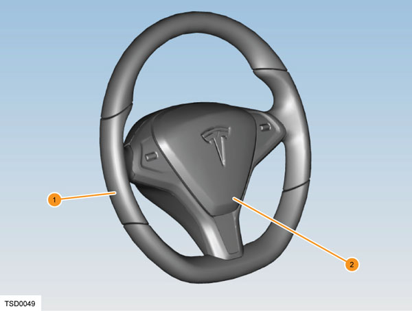
| 1. Steering wheel 2. Driver front airbag |
| Driver Front Airbag |
Mounted on the steering wheel, the driver airbag is a dual stage front airbag that provides protection from impact with the steering wheel and the surrounding dashboard for adults of all sizes.
Passenger Front Airbaglink
 |
|---|
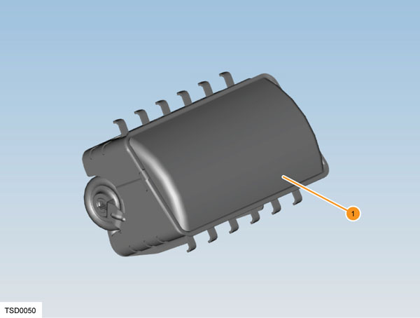
| 1. Passenger front airbag |
| Passenger Front Airbag |
The passenger front airbag is mounted under the instrument panel on the front passenger side. Similar to the driver, the passenger front airbag is dual stage. The passenger airbag provides protection for occupants based on their size as calculated by the Occupant Classification System (OCS). If the seat is empty, the occupant is determined as too small, or a child seat is detected, the airbag does not deploy.
Front Seat Side Airbaglink
 |
|---|
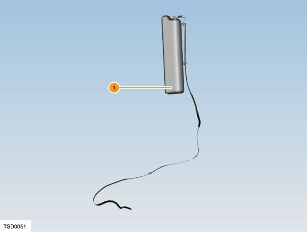
| 1. Side airbag (front row outboard) |
| Front Seat Side Airbag |
The side airbags are part of the front seats. The seat side airbags are deployed from the outboard side of the seat, forming a cushion between the occupant and the door, protecting the occupant’s upper torso and pelvis area during a side impact.
Side Curtain Airbagslink
 |
|---|
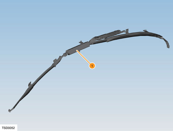
| 1. Side curtain airbag |
| Side Curtain Airbags |
The side curtain airbags are located near the side roof rails. They inflate over the full area of the front and rear side windows to form a cushion, protecting the occupant’s head from contact with the window frame or pillar(s) in a side-impact collision. The side curtain airbag deploys downwards from the top and drapes over the entire glass area. The side curtain airbags stay inflated for a few seconds after a collision in case the vehicle rolls over.
Knee Airbaglink
 |
|---|
| 1. Knee airbag |
| Knee Airbag |
Knee airbags for the driver and front passenger are located on the lower part of their respective dashboards and are designed to deploy against the occupant’s lower legs, reducing the forward momentum of the lower body during a mid- to high-speed frontal impact. Driver side deployment is dependent on the logic determined by the PSRCM, and passenger side deployment is dependent on the logic determined by the OCS and the PSRCM. When deployed, the knee airbag pushes against the occupant's lower legs, contacting them at the knee cap level, cushioning the legs down to the shin and ankle level. This holds the occupant properly positioned in the seat.
Steering Columnlink
 |
|---|
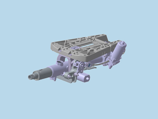
| 1. Steering column carrier 2. Tilt motor 3. Telescopic motor 4. Steering shaft 5. Collapse track |
| Steering Column |
The steering column is designed to absorb energy and collapse during frontal collisions, in order to decrease the chance of injury to the driver. The column has 100mm of collapsible travel. A deformable wire adds resistance to the collapsing motion. If the vehicle has been in a collision that caused driver airbag deployment, the column should be inspected to check whether it collapsed.
Warning
The steering column must be inspected whenever the driver airbag has deployed. Refer to BR-14-20-001 for inspection instructions.
Clockspringlink
 |
|---|
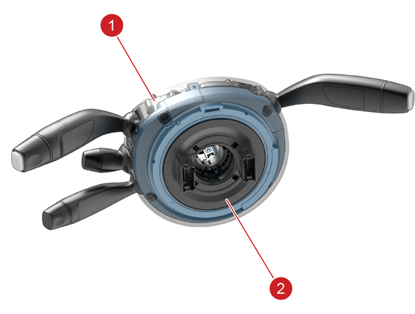
| 1. Steering column control module 2. Clockspring |
| Clockspring |
The clockspring is encapsulated into a plastic cassette, contained within the Steering Column Control Module (SCCM). The cassette consists of an outer and inner housing, with integral connectors that contain a flat ribbon flexible cable with four wires carrying out the following functions:
- Positive feed to the inflator module, stage 1 and 2
- Ground to the inflator module, stage 1 and 2
Seat Belt Pretensioner — First Row Seats Onlylink
 |
|---|
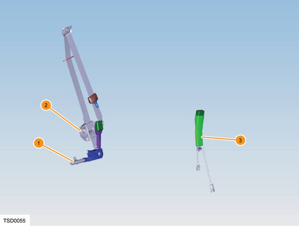
| 1. Lap belt pretensioner 2. Shoulder belt retractor and pretensioner 3. Seat belt buckle |
| Seat Belt Pretensioner — First Row Seats Only |
The driver and first row passenger seat belt pretensioners are a dual pretensioner system. The lap belt pretensioners are mounted on the body sill side, and the shoulder belt pretensioners are integral with the retractors. The initiators of both pretensioners are part of the seat belt pretensioner deployment loop and always deploy simultaneously.
Anytime an airbag deployment occurs, the seat belt pretensioners are also deployed if the belt is buckled. The PSRCM directs current through the deployment loops to the initiator. Current passing through the initiator ignites the material in the canister, producing a rapid generation of gas. The gas produced from this reaction deploys the seat belt pretensioners, which remove slack in the lap and shoulder belts.
Seat Position Sensorlink
 |
|---|
| 1. Seat position sensor |
| Seat Position Sensor |
The seat position sensor (SPS) is used to determine the distance between the driver seat and the steering column. Information from the SPS allows the PSRCM to disable stage 2 of the airbag if the seat is forward of a pre-determined point in seat track travel (closer to the airbag module). The SPS is a Hall effect sensor, mounted on the outboard seat track of the driver seat. The seat track includes a metal bracket that shunts the SPS magnetic circuit, creating two states of seat position. The shunted state represents a rearward seat position. The non-shunted state represents a forward position. These 2 states are inputs to the PSRCM.
When an SPS informs the PSRCM that the state 1 threshold is reached (seat is rearward), the PSRCM does not disable stage 2. When the state 2 threshold is reached (seat is forward), the PSRCM disables stage 2 deployment of the driver airbag.
Note
Stage 2 deployment is also disabled if the PSRCM detects that the sensor is not operating as expected.
The sensor is secured to the seat track with two rivets.
Impact Sensorslink
 |
|---|
| 1. Impact sensor - accelerometer type |
| Impact Sensors |
Eight impact sensors are fitted to the Model S. They are either accelerometer type sensors or pressure sensors, and are fitted in the following positions:
- Front bumper carrier sensors (x2) - accelerometers
- ‘B’ pillar sensors (x2) - accelerometers (for vehicles without Pedestrian Protection)
- ‘C’ pillar sensors (x2) - accelerometers
- Front door sensors (x2) - pressure sensors
For Model S vehicles built after February 2019, there are two additional sensor types:
- Shotgun sensors (x2) - accelerometers
- Pedestrian Protection sensors (x2) - accelerometers
There are four additional accelerometer sensors located near the front of the vehicle - one pair on the shotgun structure, and one pair on the fascia (see the sensor location image near the front of this document). All impact sensors on vehicles produced after February 2019 are no longer Delphi sensors, but Bosch sensors. There are different body/mounting plates and an updated harness for the new Bosch RCM.
The accelerometer type impact sensors contain a sensing device that monitors vehicle acceleration to detect collisions that are severe enough to warrant airbag deployment. The impact sensors are not part of the deployment loop, but instead provide input to the PSRCM. The PSRCM contains a microprocessor that performs calculations using the measured accelerations and compares these calculations to a value stored in memory. When the calculations exceed the stored value, the PSRCM directs current through the deployment loops, deploying the appropriate airbags and the seat belt pretensioners.
 |
|---|
| 1. Impact sensor - Pressure type |
The Piezo-electric pressure sensors mounted inside the front LH and RH doors measure the dynamic pressure change caused by deformation of the door in a side impact.
The inputs from the pressure sensors are processed by the PSRCM to deploy the side airbags and the seat belt pretensioners.
Note
It is extremely important to always reinstall or replace any plugs or tape removed from the door shells when servicing components inside the door. The pressure sensors are precisely calibrated to respond to pressure changes within the door in the event of a collision. Opening more holes in the door creates more escape paths for air, which diminishes the sensor's ability to accurately detect a side impact, and can negatively affect airbag deployment.
Occupant Classification System (OCS)link
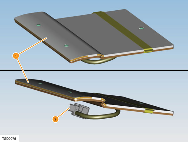 |
|---|
| 1. OCS sensor mat (fluid filled) 2. ECU |
The OCS monitors the seated weight and pattern to estimate the type of occupant sitting in the front passenger seat, and communicates the status to the PSRCM using a CAN signal. The PSRCM uses this information to determine whether to enable or suppress the deployment of the front passenger airbag and corresponding knee airbag.
Note
This system is only available on the front passenger seat of USA vehicles.
The OCS consists of:
- an electronic control unit (ECU)
- a sensor mat in the seat
- a harness
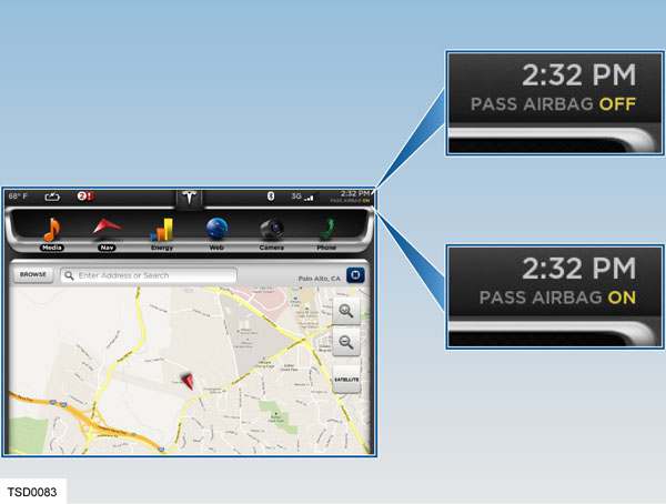
- a passenger airbag ON/OFF indicator.
The OCS measures the pressure change in the mat fluid (and pattern through cell arrangement) to determine the type of occupant in the front passenger seat. The ECU compares this pressure change to the internally stored threshold to determine whether the seat is occupied, and what size of passenger is detected (see table below). The OCS sends this information to the PSRCM to either disable the front passenger airbag and knee airbag or enable stage 2 of the airbag system.
The PSRCM notifies the occupants of the disable status by displaying the passenger airbag ON/OFF indicator.
If a fault is detected, the OCS sends a message to the PSRCM. The PSRCM responds by sending a command message to the instrument cluster to display the TSRS system AIRBAG indicator.
 |
|---|
| Front Passenger Seat Occupancy | Telltale |
|---|---|
| Seat empty | PASS AIRBAG OFF |
| Infant in child seat (up to 20 lbs) | PASS AIRBAG OFF |
| Child or small occupant (20-100 lbs) | PASS AIRBAG ON/OFF |
| Heavy object or occupant | PASS AIRBAG ON |
Note
Values are approximate. Occupants whose weight is close to the low weight threshold can cause the status to occasionally switch on and off depending on seating position and physique.
The Occupant Classification System (OCS) is precisely calibrated for each individual seat at the factory. When servicing the OCS or the Seat Assembly with OCS, Tesla’s service procedures must be followed so that OCS system function is not compromised. Any service performed on the Seat Assembly with OCS must be followed by a Seat Re-Zero procedure.
Vehicles built after February 2019 have a different OCS than earlier vehicles, the newer OCS is not backwards compatible with previous Model S seats.
Seat Belt Reminder (SBR) Sensorslink
 |
|---|
| 1. SBR sensor |
The SBR sensors are fitted in the seat cushion of the appropriate seat. On USA specification vehicles, it is only fitted in the driver’s seat. On all vehicles, regardless of market, the driver seat SBR switch is an input to the body control module (BCM). The BCM sends the state of the sensor to the PSRCM over the CAN bus. The BCM also uses this input for vehicle on/off, gear selection, and parking brake behavior.
SBR sensors are fitted to all five seating positions of the first and second row seats on EMEA and APAC market vehicles. The SBRs always actuate for 5th percentile occupants and larger, but may actuate for other smaller occupants or objects below this weight. The PSRCM uses this signal, together with information from each seat belt buckle, to display an indicator light and sound an audible warning if an occupant has not fastened a seat belt.
Behavior definitions for EMEA and APAC markets are pending.
Note
On EMEA and APAC vehicles, the seat belt warning indicator is on the touchscreen, but the chime operates as described above if a rear seat is occupied with the seat belt unfastened.
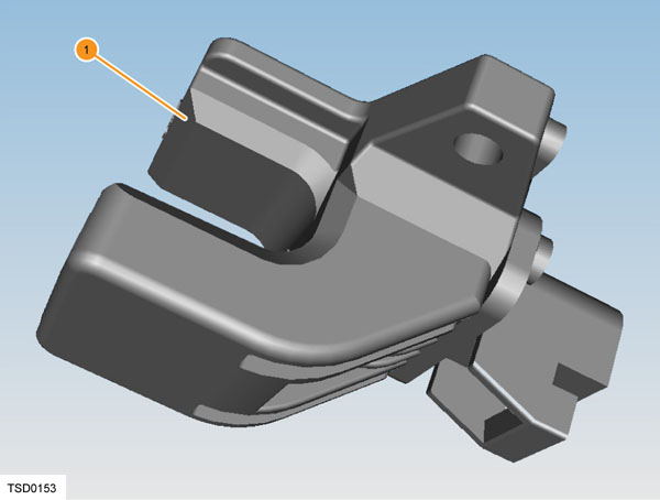
Pedestrian Protection Programlink
 |
|---|
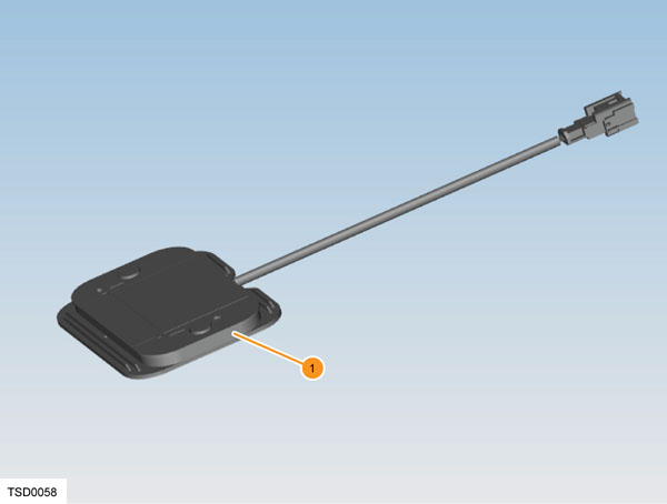
| 1. Pedestrian Protection System - Pressure Sensor |
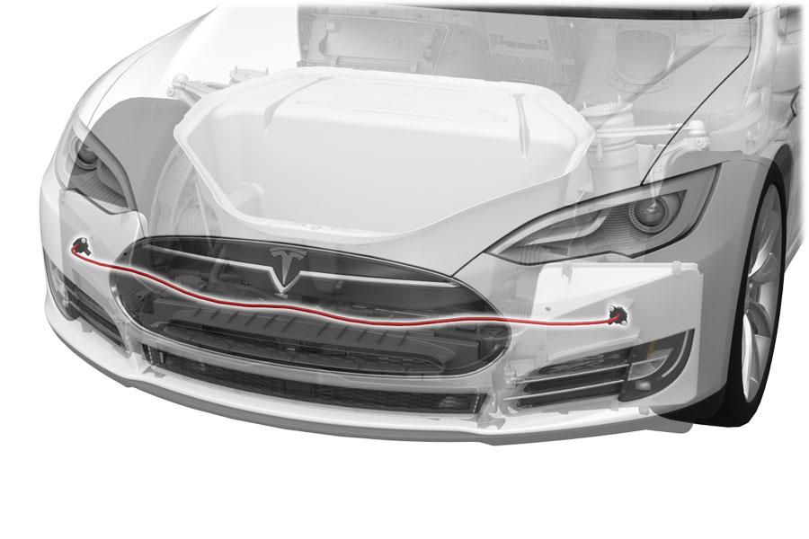
Model S vehicles sold in EMEA and APAC which were built from start of production through April 10, 2016 that were sold in EMEA and APAC are equipped with the Pedestrian Protection System. The system is made up of a pressure sensor tube and two actuators. The pressure tube senses a change in pressure then deploys the actuators in the hood. This prevents pedestrians from becoming more injured in the event of a frontal collision.
Vehicles made from April 2016 to February 2019 do not have any type pedestrian protection.
 |
|---|
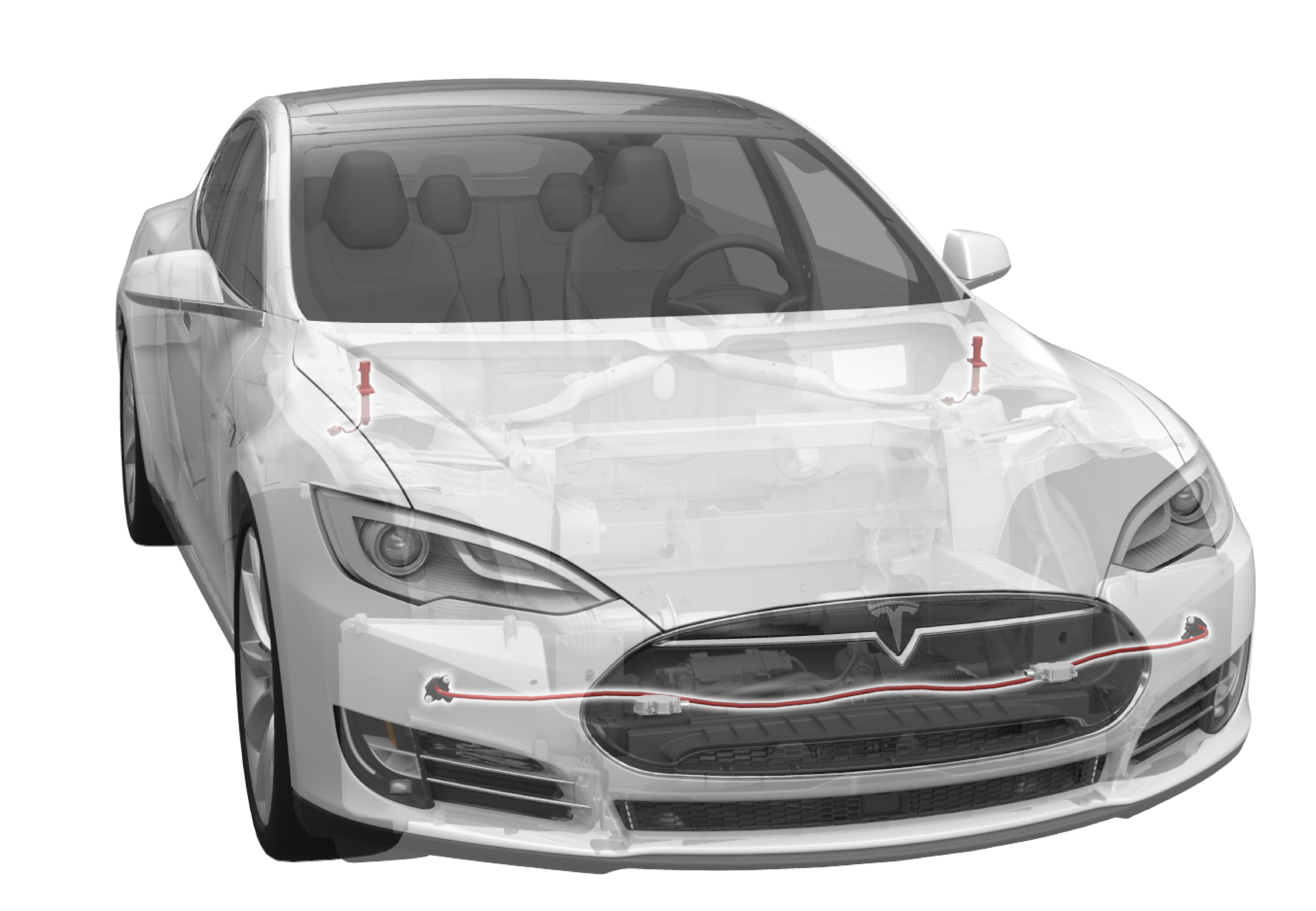
Model S vehicles built after February 2019 sold in Europe and China are equipped with an updated Pedestrian Protection System. The system is made up of:
- a pressure sensor tube assembly located in the bumper foam
- two accelerometer sensors located on the front fascia
- two hood actuators
The pressure tube, along with the accelerometers, sense the change in pressure and acceleration, then deploys the actuators in the hood to create empty space under the hood. This decreases the severity of injury and protects the pedestrian from becoming more injured in the event of a frontal collision.
Operationlink
Starting and Drivinglink
 |
|---|
| 1. Airbag indicator light 2. Front seat belt indicator light |
The airbag warning indicator displays for six seconds when the vehicle is switched on as a system check. After the system check, if there is no active fault, the indicator turns off and stays off. If there is an active fault, the indicator turns off for one second and then turns back on for the remainder of the ignition cycle, or until the fault is no longer active.
The front seat belt indicator and chime are controlled by the PSRCM based on input from the SBR switches and, in the United States market, the OCS. The passenger seat SBR and the OCS are inputs to the PSRCM. The front seat SBR system has three classes of operation for each seat.
If the seat belt is fastened during any of the three stages, the chime stops and the indicator turns off.
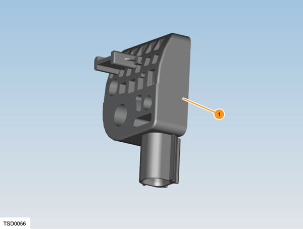
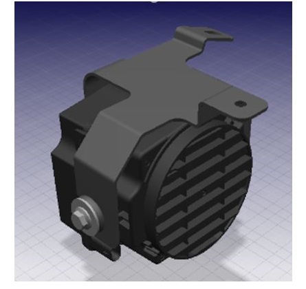
Pedestrian Warning Systemlink
 |
|---|
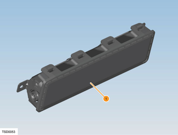
| Pedestrian Warning Speaker in vehicles built before September 2020 |
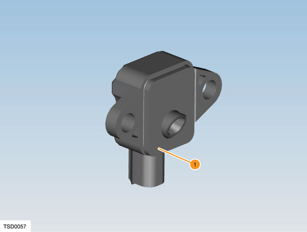
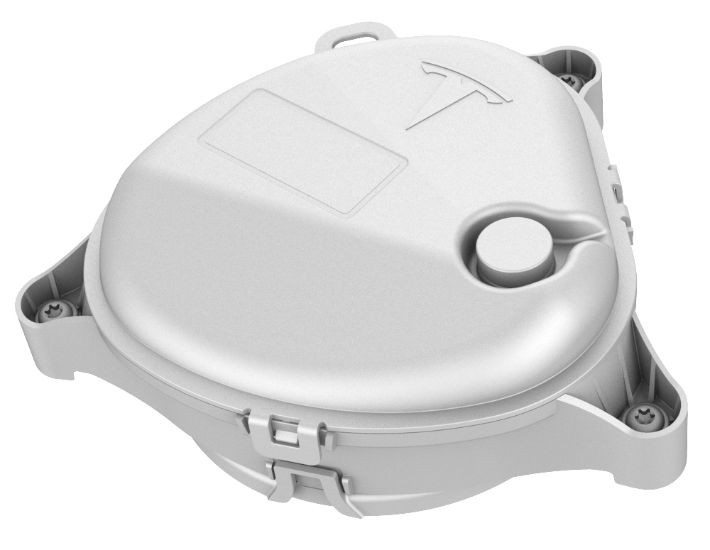 |
|---|
| Vehicles built after September 2020 have a bracket so that the new speaker can fit on the front fascia |
| Pedestrian Warning Speakerin vehicles built after September 2020 |
Functionality and Purposelink
The Pedestrian Warning System (PWS) encompasses a speaker enclosed in a box at the right hand front of the vehicle, located on the front fascia. The PWS is a legal requirement based off region, the specifics of the requirement (pitch of noise, speed of vehicle etc) is dependent on which region the vehicle is located. Electric vehicles traveling at slow speeds must emit a noise to warn pedestrians of motion. As soon as a vehicle is put into gear the speaker emits a noise. Vehicles in the APAC market, not including Japan, have the ability to turn off the PWS.
Drive
The speaker emits a noise while the vehicle is in drive. As the vehicle accelerates, the noise goes up in pitch. Once the vehicle reaches a speed of 30kph/19mph the noise begins to fade out The forward motion noise sounds similar to a spinning fan and Tesla has taken precatuion to minimize the noise for customers inside the vehicle, the intent is that the Pedestrian Warning Speaker is only heard from outside the vehicle.
Reverse
When the vehicle is in reverse, the noise emitted by the PWS needs to be heard at the rear of the vehicle. Due to the fact that the speaker is located at the front of the vehicle, the noise for reverse is increased and can be heard within the vehicle. The sound while in reverse is more of a tone. The noise in reverse intentionally sounds different than the noise in Drive. No matter what the speed, the PWS will emit a noise while in reverse.
As of September 2020, the United States requires all new electric vehicles to be equipped with the Pedestrian Warning System. With the new requirement, Tesla improved the system to be less noticeable for customers within the vehicle. Vehicles built prior to September 2020 have the potential to hear the PWS while within the vehicle.
Communication The PWS receives messages via the UI. The drive inverter reports the gear and the speed of the vehicle to the gateway. The gateway then communicates this information to the UI where the audio system then transmits the appropriate noise based off these inputs. The audio system in the vehicle includes microphones, the amplifier that then communicates to all speakers. If there are issues with the Pedestrian Warning System, a good first debug step would be to check the other speakers in the vehicle to pinpoint if the issue is with the audio system as a whole or the Pedestrian Warning Speaker.