Air Suspensionlink
Last updated: October 10, 2024
Overviewlink
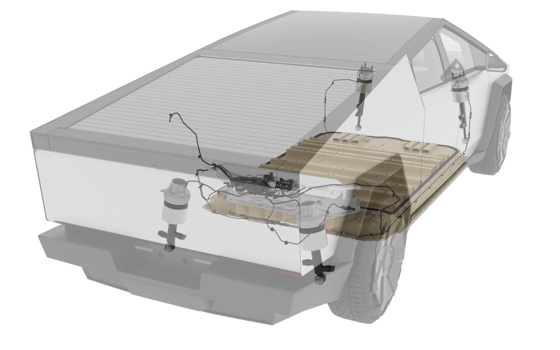
Cybertruck features the Tesla Air Suspension (TAS) system to maintain vehicle ride height across load conditions while driving and provides useful functionality for towing, hauling, and off-roading. There are four air spring modules, one at each corner of the vehicle. Vehicle ride height is measured by four ride height sensors, one at each corner. The air compressor provides compressed air to the TAS valve block through an air line. The TAS valve block is used to control how much air flows to each corner air spring, and the reservoir. The TAS system utilizes the VCREAR, VCLEFT, and VCRIGHT Electronic Control Units (ECUs) for controls and sensing. The pressurized pack system uses a valve block to control pressurized air flow into the high voltage battery pack during wade events.
 |
|---|
| Air Suspension System Overview |
Note
For TAS to function, the mid voltage system and communications must also be functioning.
Componentslink
Air Spring Modulelink
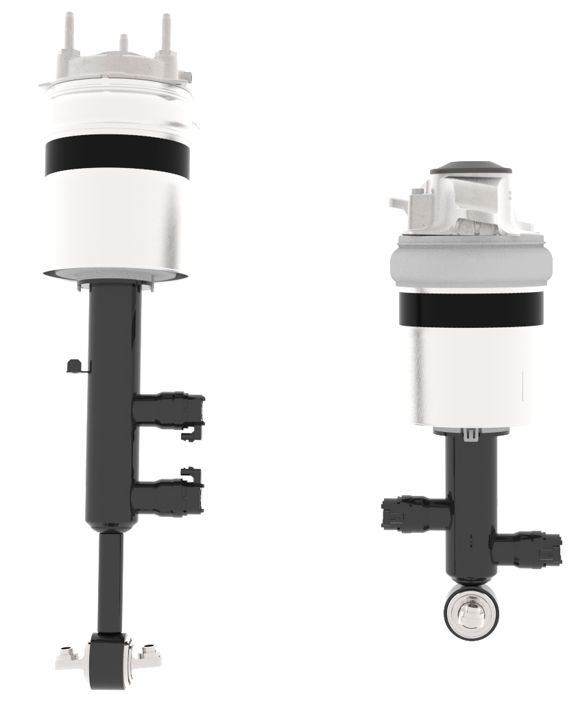
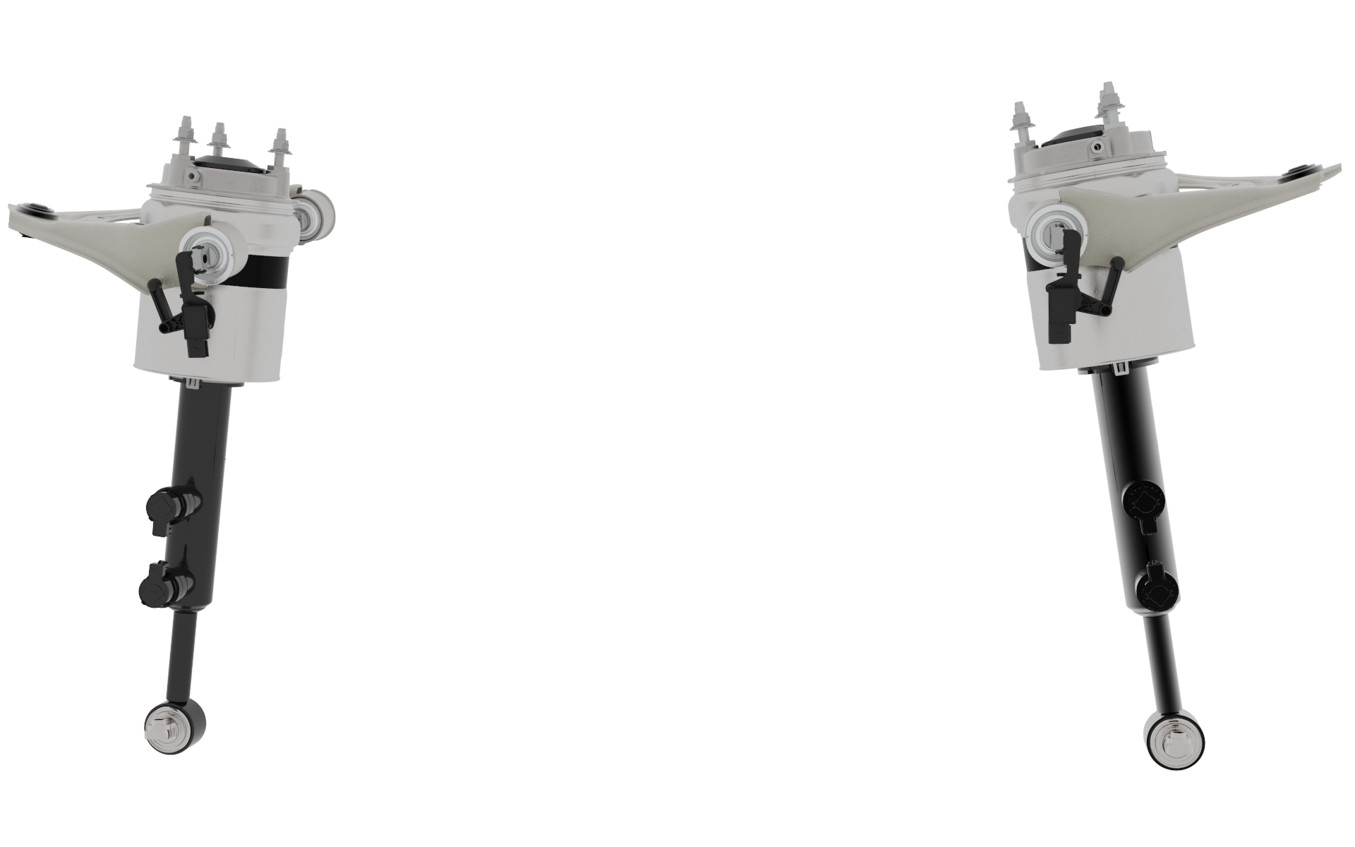
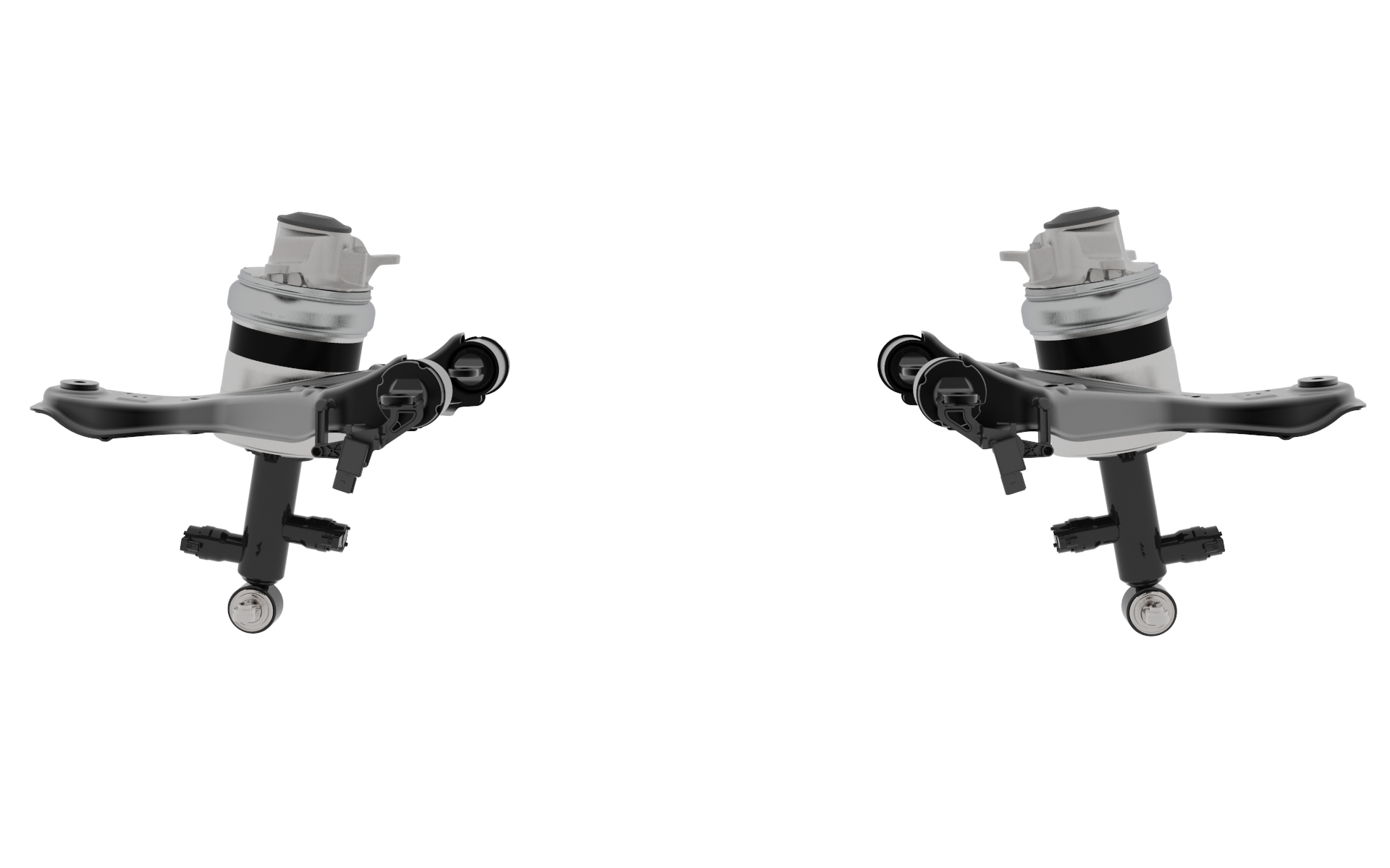
There are four air spring modules on Cybertruck, one located at each corner of the vehicle. The top mount casting is rigidly mounted to the vehicle body, the lower mount is connected through a bar pin on the lower control arm.
 |
|---|
| Air Spring Modules - Front (Shown Left) and Rear (Shown Right) |
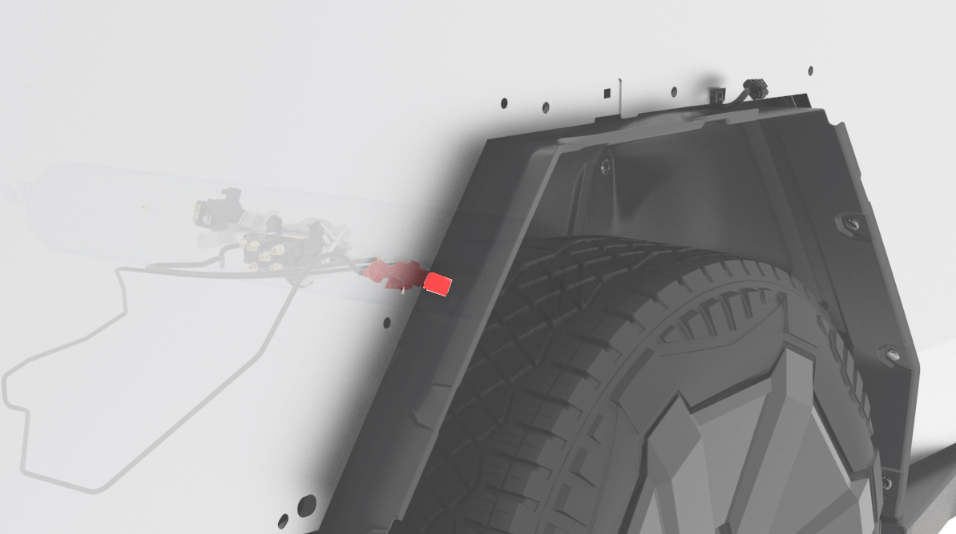
The module consists of an air spring and an adaptive damper. Each spring uses a fiber reinforced rubber sleeve that rolls along a contour. An aluminum restraining cylinder constrains the radial inflation of the sleeve. As the spring inflates, the length of the overall module increases between the top body mount and the lower knuckle mount, raising the vehicle and increasing the spring's air volume. Air moves into the air spring module through a plastic tube (air line) near the top of the spring. The tube is secured to the air spring through a brass fitting that grips onto the airline and forms an airtight seal. The front air spring fitting is mounted to the side of the top mount, accessible through the wheel well. The rear air spring fitting is mounted to the top of the top mount, accessible through the bed access panel.
Static spring pressures may range from 5.5 bara (65 psig) to 12 bara (160 psig), while dynamic spring pressures (ex: hitting a large curb at speed or lifting a tire while offroading) may range from 1.5 bara (7 psig) to 21 bara (300 psig). Air spring burst pressure is ~30 bara.
The air spring module features a twin-tube hydraulic damper with two solenoid valves used to control oil flow in the rebound and compression directions independently. The top solenoid valve controls the rebound damping characteristics and the bottom solenoid valve controls the compression damping characteristics. The goal of the adaptive damping suspension is to control transient oscillations and minimize body motions. The front right damper solenoid is current-controlled via PWM signal and is powered by the VCRIGHT, the front left is controlled and powered by VCLEFT. The rear 2 damper solenoids are both powered and controlled by VCREAR. There are 4 suspension accelerometers, 1 on each corner, that are used for damping controls in conjunction with ride height sensors. The front damping accelerometers are both powered by and send their A2B signals to VCRIGHT. The rear are both powered by and send their A2B signals to VCREAR.
Air Spring Serviceabilitylink
The air spring is fully replaceable, and outside of replacing the fitting, it is not internally serviceable. When replacing an air fitting take care to apply the correct torque to avoid stripping the threads. Torque specs may vary by model or build pedigree, please reference the latest design torque spec in the service manual. When replacing an air fitting make sure the circular brass ring, named the Collet, is in the correct upright orientation to seal the conical surface that mates with the air fitting.
When diagnosing leaking air suspension symptoms, note that the air spring features several rubber seals that are potential sources of air to escape. If there is a leak in the system it may be due to a small leak in an air line, fitting, or the air spring seals.
Air leak repairs are confirmed by taping the fender to the wheel and letting the car sit for 24 hours in jack mode. If there is slack in the tape after the duration, this indicates the suspension lowered due to a persistent leak in the system.
Note
Temperature effects may cause ride height changes as air expands and contracts.
Valve Blockslink
There are two valve blocks on Cybertruck, the Air Suspension valve block and the Pressurized Pack valve block. Both valve blocks are mounted on the reservoir tank, located under the bed access panel. The Air Suspension valve block is optimized for rapid axle leveling with consistent air flow through the valves. The Pressurized Pack valve block provides a method of active water ingress protection when the vehicle wades through water.
Tesla Air Suspension Valve Blocklink
The air suspension valve block is comprised of seven normally closed solenoid valves. The valves are current-controlled from gate-drivers on VCREAR using a PWM signal that commands an initial high current ("push-current") to open the valve and then a constant, lower current ("hold current") to keep the valve open. This is called push-and-hold control. There are only six valves in the TAS valve block where airlines are inserted. Six of seven valves control airflow between the air line fittings and the internal valve block volume of air (gallery). The seventh valve, called the cross-link (XLINK) valve, is internal to the valve block with no external air fitting.
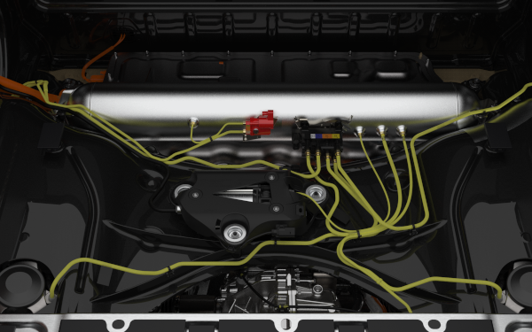
 |
|---|
| TAS Valve Block Location |
The valve block has a color-coded label next to the air fittings that helps match the correct colored air line for insertion.
 |
|---|
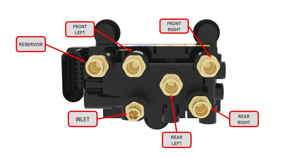
| TAS Valve Block Solenoid Valves |
The seven valves can be broken down in four groups based on their function:
| Valves | Function |
|---|---|
| Front Left, Front Right, Rear Left, Rear Right | Control airflow between the air spring modules and the internal valve block gallery. |
| Reservoir | Controls airflow between the gallery and air reservoir. |
| Inlet | Controls airflow between the gallery and compressor. |
| Xlink | Pneumatically connects the rear left and rear right air springs, allowing for greater articulation while off-roading. |
There is one pressure transducer internal to the valve block which is exposed to the gallery. The pressure transducer measures the pressure of the springs and the air reservoir by selectively opening valves to the gallery and allowing pressure to equalize.
Pressurized Pack Blocklink
The Pressurized Pack valve block contains a single valve and is positioned next to the TAS valve block.
 |
|---|
| Pressurized Pack Valve Block Location |
The valve directly connects the air reservoir and the battery pack ancillary volume. It controls the flow of pressurized air into the HV pack as a method of active water ingress protection when the vehicle wades through water with the pack submerged. The Pressurized Pack valve block has two fittings, with one air line to the air reservoir and the other to the pyro hatch cover. The valve block has a color-coded label that matches colors on the air lines to encourage correct insertion.
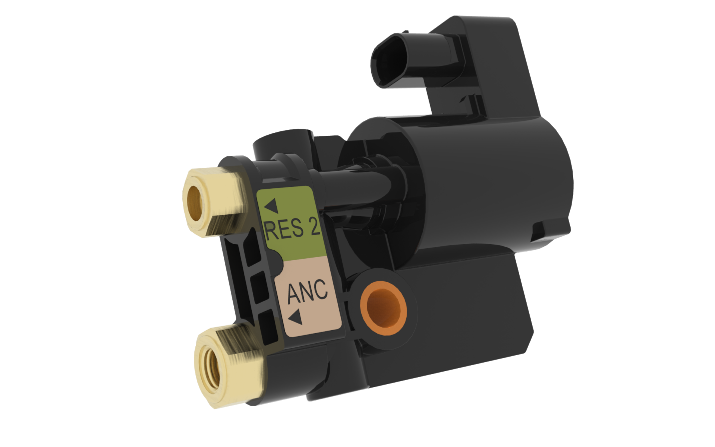 |
|---|
| Pressurized Pack Valve Block |
Valve Block Serviceabilitylink
The TAS and Pressurized Pack valve blocks are fully replaceable, and the air fittings are replaceable. If a fitting is removed it is recommended to always replace that fitting with a new one, ensuring that the plastic assembly plug is not removed until the fitting is installed, so the collet maintains proper orientation. There are no serviceable parts within the valve blocks.
Note: Moisture in the system can lead to corrosion within the valve block or may result in valves freezing open/closed in low ambient temperatures.
Air Suspension Lineslink
There are a total of 13 plastic air lines used for distributing compressed air throughout the vehicle. These are grouped into five separate bundles which are installed at the factory. Note that the DU Breather air line is not pressurized, see Drive Unit Theory of Operations for more detail.
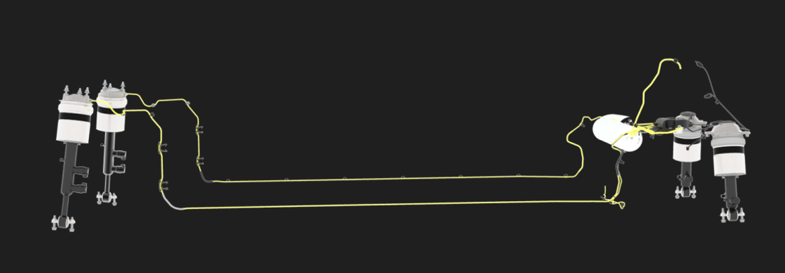 |
|---|
| Air Suspension Lines |
| Air Line Name | Length (mm) | Bundle |
|---|---|---|
| Front Left | 5142 | 1250936-00 |
| Intake | 1348 | 1250936-00 |
| Reservoir to Valve Block | 236 | 1250936-00 |
| Valve Block to Ancillary | 2175 | 1250936-00 |
| Front Right | 5424 | 1250937-00 |
| Air Fill | 1722 | 1250938-00 |
| Boost | 572 | 1250938-00 |
| Drive Unit Breather | 1582 | 1250938-00 |
| Rear Left | 1109 | 1250938-00 |
| Rear Right | 841 | 1250938-00 |
| Inlet | 322 | 1250939-00 |
| Ancillary to High Voltage Battery | 722 | 1949807-00 |
The Intake line is located behind the rear left bed panel. It ingests ambient air into the TAS system.
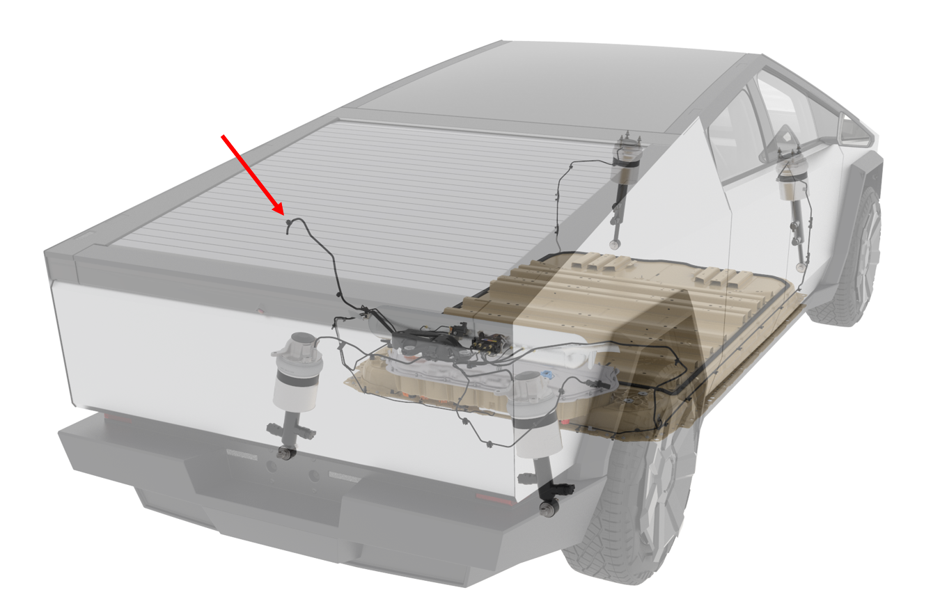 |
|---|
| Air Intake |
There is an air line behind the rear right wheel liner used by service to fill the air reservoir with nitrogen. The fitting on the air fill line is an "R1234yf" high side type.
Note: The fill port is only meant to fill the reservoir, not to remove air from the system.
 |
|---|
| Nitrogen Fill Port - R1234yf Type Fitting |
The Reservoir to Valve Block, Valve Block to Ancillary, and Ancillary to High Voltage Battery air lines enable Pressurized Pack functionality.
Air Line Serviceabilitylink
All air lines are replaceable. The front right and left air spring lines are difficult to fully remove since they run alongside the battery pack inside the body. In the case of air line damage, refer to the Service Manual for instructions and guidelines on performing a splice repair.
Air Compressorlink
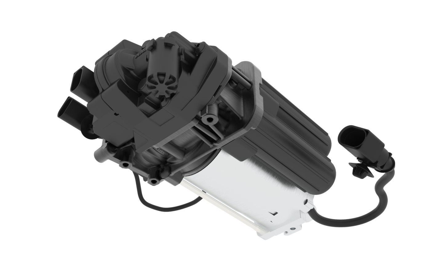
The Air Compressor is used to inflate TAS system with compressed air. The compressor is a 2-stage piston compressor. Both stages run simultaneously and are capable of raising the pressure from 1 to 21 bara. The first stage is lower pressure and higher volume, using a larger piston. The second stage is higher pressure, using a smaller piston. There is a separate inlet and outlet for air to flow.
 |
|---|
| Air Suspension Compressor |
As air is drawn into the compressor through the inlet, it first passes through a plastic filter to remove airborne particulate that could cause damage to the compressor and valve block. The air dryer is a narrow channel of silica balls, which acts as a desiccant. The desiccant removes moisture from the ambient air before it reaches the compressor valves and TAS valve block.
When the air spring modules lower the ride height or when air exhausts from the reservoir, dry air travels back through the air compressor and through the desiccant in the air dryer. This purges the moisture stored in the air dryer back into the ambient environment, thus regenerating the desiccant dryer and making it capable of accepting moisture on the next compression cycle.
In normal operation, with the exception of the Pressurized Pack function, all air that enters the system enters through the dryer, and then exits through the dryer. This cycle allows the dryer to remain recharged and keep the system dry. When a leak is introduced, dry air escapes directly to ambient and bypasses the dryer, and as the compressor runs to replace that lost air, moisture begins to build up in the dryer. The system will act to intentionally regenerate the dryer by exhausting air directly from the reservoir to ambient, but with a sufficiently large leak, the dryer will become saturated and can no longer dry air to protect the system.
Excessive moisture in the TAS system can cause corrosion, freezing valves, and lead to electrical component failure. There are two valves inside the compressor. The boost solenoid valve in the compressor allows air from the reservoir to flow directly into the second stage of the compressor, allowing for faster spring filling when the reservoir is at lower pressures. The exhaust valve is a piloted valve which opens the gallery to atmosphere and allows air to flow through the exhaust muffler. The muffler is filled with Nylon wool material used to dampen the sound of the escaping air. The TAS air compressor on Cybertruck has a brushed DC 48 V motor with runtime parameters that are controlled by VCREAR.
The air compressor uses a resistive temperature thermistor located on the piston cylinder head to prevent the compressor from overheating. When the compressor reaches its thermal limit, it must cool down before continuing to run. The compressor will stop at a lower thermal limit when filling the reservoir than when filling the springs, so that there is some thermal headroom to allow for a ride height change if the user requests it. This increases system availability and prevents a situation where the compressor becomes unavailable only because it was being used to refill the reservoir.
Air Compressor Serviceabilitylink
The air compressor is fully replaceable but not internally serviceable.
Air Reservoirlink
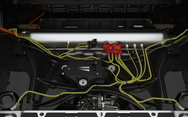
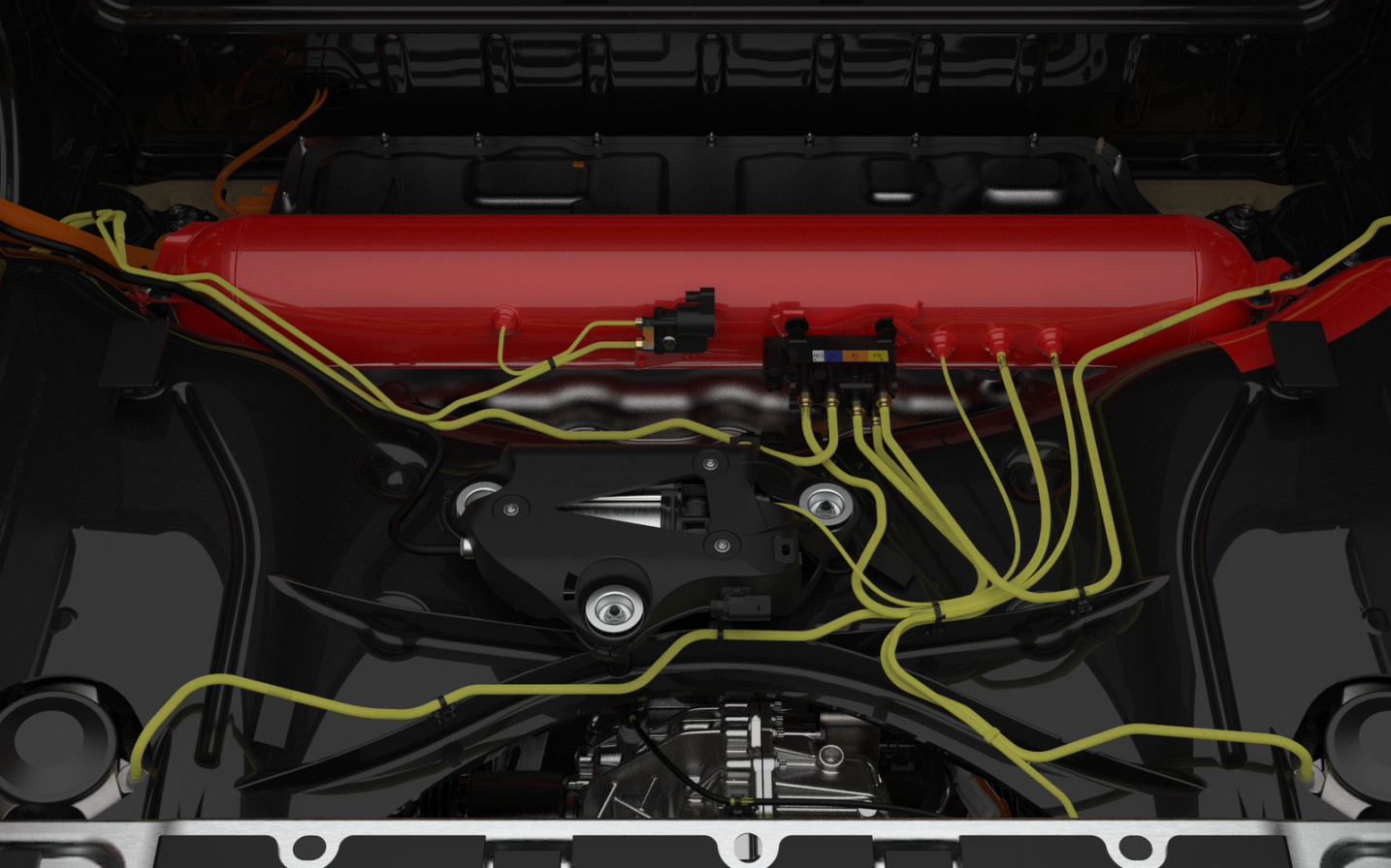
The air reservoir stores compressed air from the compressor until the air is needed to fill the air springs or the Pressurized Pack system. The nominal operating pressure in the reservoir is 21 bara, and the reservoir tank volume is 17.4L.
 |
|---|
| Valve Blocks Mounted on the Reservoir |
The reservoir serves as a mount for both of the TAS and Pressurized Pack valve blocks. The air reservoir has 4 fittings on it which provide direct reservoir access for a reservoir air line to the compressor (BOOST), a reservoir air line to the TAS valve block, a reservoir line to the Pressurized Pack valve block, and a reservoir air line to the service Air Fill port.
Reservoir Serviceabilitylink
The air reservoir can be removed by removing the bed access panel and loosening both fasteners that mount to the rear underbody. The reservoir can be pivoted to the right side of the bed to allow for access to the Ancillary Bay cover without disconnecting the air lines. The air reservoir is replaceable but has no serviceable components other than fittings.
Nitrogen is used in service to fill the system because it does not contain any moisture and is readily available in service.
Ride Height Sensorslink
There is one ride height sensor located at each corner of the vehicle, four in total. The ride height sensor brackets are mounted to the vehicle body, and connected through a linkage to the corresponding control arm. They are used to measure the vehicle’s ride height, which is adjustable with the air suspension system. The height sensors are Contactless Inductive Position Sensors powered with 5V. The front left is powered by and communicates with VCLEFT. The front right is powered by and communicates with VCRIGHT. The rear 2 sensors are powered by and communicate with VCREAR. The height sensors output Pulse-Width Modulation (PWM) signals at a frequency of 800 Hz with duty cycle proportional to sensor angle. The respective controller converts this duty cycle to vehicle height through a lookup table called a ride height table. The sensor reading is initially calibrated in the factory when the vehicle is raised to MEDIUM height and a laser system measures the true vehicle height at all 4 corners of the battery pack. These values are stored in non-volatile memory (NVM).
 |
|---|
| Front Ride Height Sensors |
 |
|---|
| Rear Ride Height Sensors |
Ride Height Sensor Serviceabilitylink
The ride height sensors are not internally serviceable but are replaceable as an assembly with the bracket included.
Tesla Air Suspension (TAS) Controllerlink
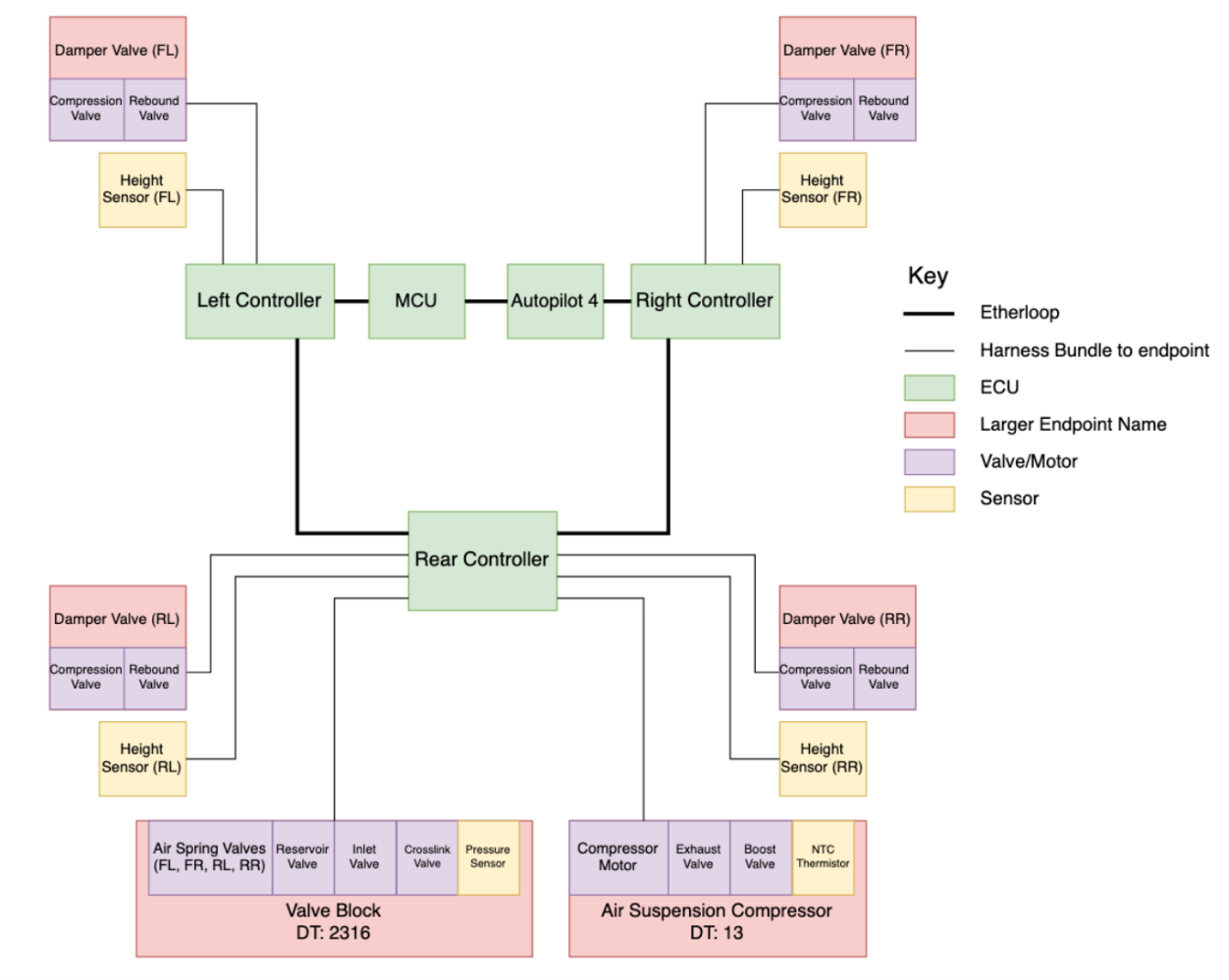
The TAS controller has been incorporated into VCREAR. VCLEFT and VCRIGHT are used to power the front height sensors and control the adaptive damping solenoid valves, and communicate sensor measurements to VCREAR over etherloop. VCREAR powers and communicates with the TAS valve block, Pressurized Pack valve block, air compressor, height sensors, and damper valves.
 |
|---|
| Air Suspension Controller Block Diagram |
Leveling and Modeslink
Leveling Controlslink
The ride height sensors are used to monitor ride height in real time and decide whether to start, continue, or stop leveling. Leveling controls are optimized around “flat leveling,” which keeps the vehicle level to the ground by raising all springs at once when leveling up and lowering all springs when leveling down. When the vehicle is heavily loaded or reservoir pressure is below approximately 12 bara, the system may transition axle-leveling, raising or lowering one axle at a time.
Ride Height Modeslink
Cybertruck uses a mode-based approach to ride heights rather than a simple height slider as Model S and Model X use.
On-roadlink
For all on-road driving, the user will have an option to raise to High level and will have no other manual ride height controls. In some on-road vehicle modes, the user will have a choice of Default Ride Height and can choose between Medium and LOW. Regardless of selection, the vehicle will adjust to LOW on highways and at high speeds. In Sport vehicle mode, default ride height is Low. In Comfort vehicle mode, default ride height is Medium.
Off-roadlink
The user can choose High or Very High levels for TAS, without any other manual ride height controls available. When an off-road mode is selected, TAS automatically adjusts to High, except for Overland/Rock mode, where it will adjust to Very High. Low, and Medium cannot be selected while an off-road drive mode is active.
While driving, TAS automatically lowers from Very High to High at 25 mph, enabling high-speed driving in High. TAS will also automatically lower from Extract mode to Very High when driving at 10mph.
There is no specified automatic lowering speed at High Target.
Level Definitionslink
| Name | Level Definition (mm) | |
|---|---|---|
| Front | Rear | |
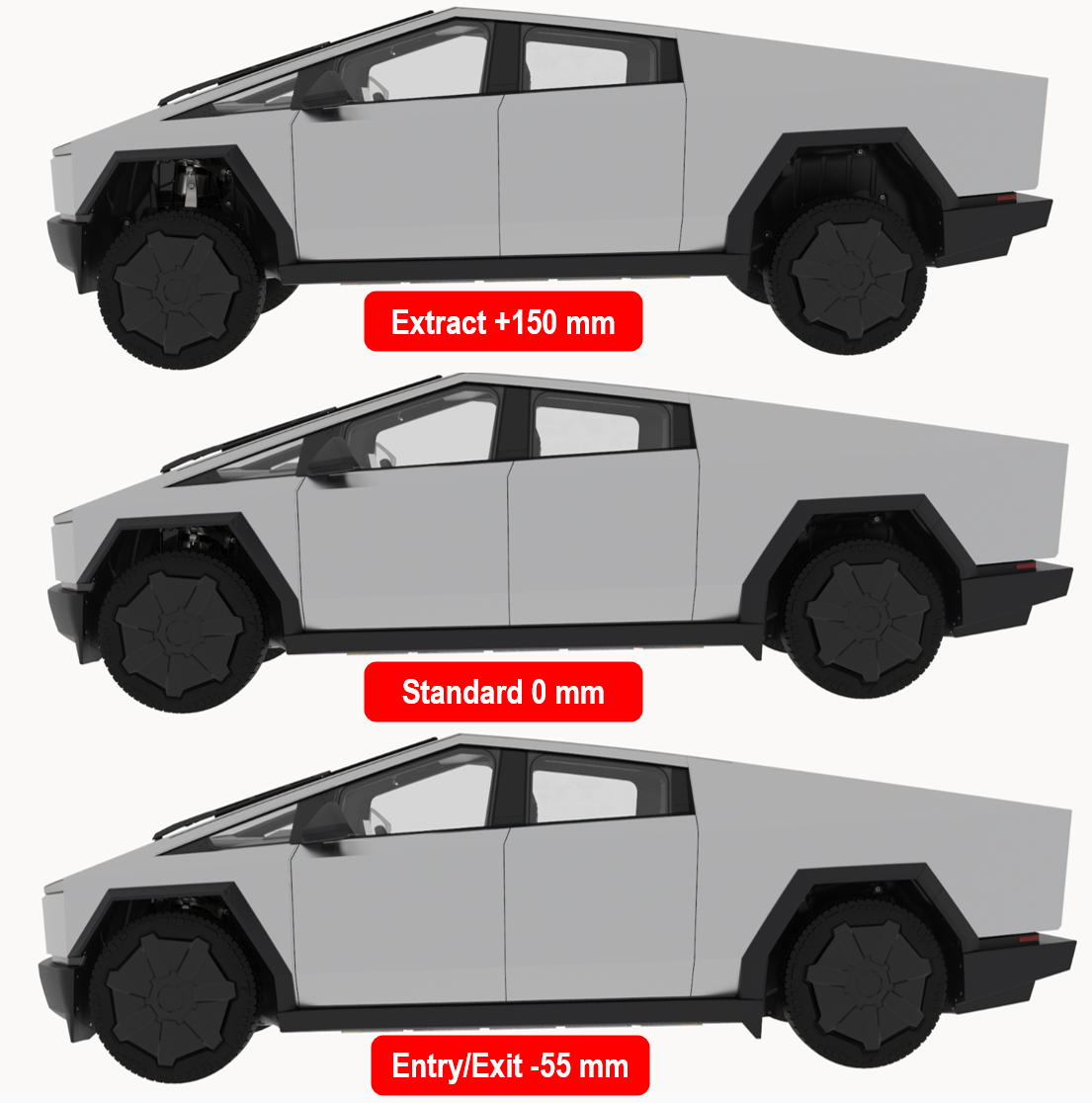
| Extract | 150 | 150 |
| Very High | 100 | 100 |
| High | 60 | 60 |
| Medium (Standard) | 0 | 0 |
| Low | -40 | -40 |
| Entry/Exit | -55 | -55 |
 |
|---|
| Air Suspension Levels - Extract, Standard, Entry/Exit |
Air Suspension Alertslink
The air suspension alerts set by the Tesla Air Suspension (TAS) controller detects missing in action (MIA) components that are expected to be powered on and talking on the bus but are reported missing by other controllers. TAS will also set alerts to indicate the following vehicle conditions: Height sensor issues, power issues, air leaks, limp modes (these can block leveling), firmware-related issues (some indicate a mismatch), controller runtime errors, user-facing messages / warnings, damping-specific issues, rough road and geofenced alerts that raise suspension under specific vehicle conditions, controller area network (CAN) communication issues, Jack Mode status, compressor operation alerts, crash detection, and blocked air lines.
These alerts are designed to assist in vehicle diagnosis. If the system is not operating as expected, investigate for the following issues: Power and communication, air suspension leaks, excessive moisture present in the system due to leaks, and ride height miscalibration.
Air Suspension Signalslink
The following list shows useful signals for diagnosing the air suspension system.
| Signal | Description |
|---|---|
| TAS_levelingState | which leveling actions are taking place |
| TAS_levelingItem | which springs are being raised or lowered |
| TAS_rawHeightXX | wheel center height, minimal filtering – positive is REBOUND |
| TAS_staticHeightEstimateXX | wheel center height, at t = ∞ (long term average) |
| TAS_filterMode | correlates with inputs to leveling and filtering (e.g. loading, driving) |
| TAS_runMode | describes overall application running mode (normal, service, factory) |
| TAS_targetLevel / TAS_currentLevel | named level that system is adjusting to or currently as (e.g. MEDIUM, HIGH) |
| TAS_pressureGallery | live pressure sensor reading inside valve block gallery |
| TAS_pressureReservoir | last known reservoir pressure |
| TAS_compressorRun | reflects all compressor run |