Seatslink
Last updated: January 06, 2025
Overviewlink
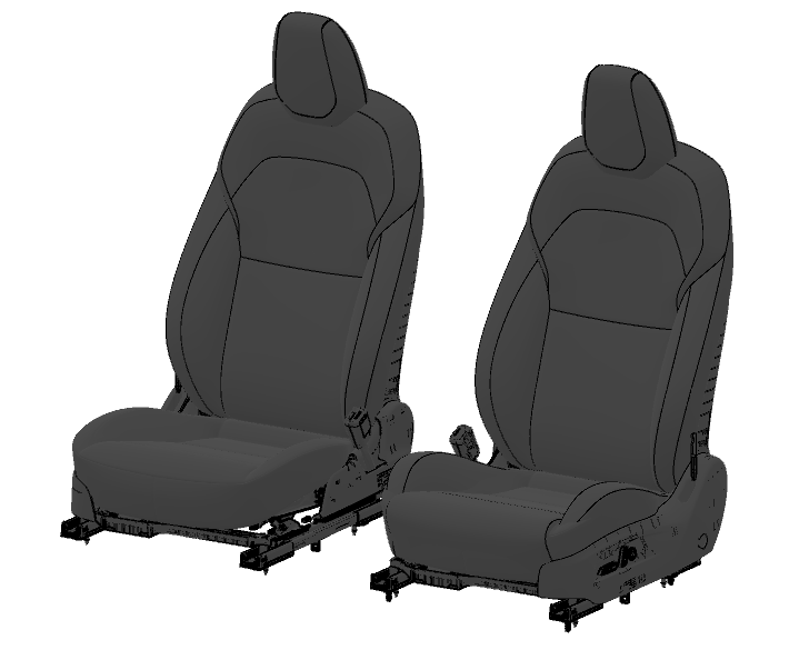
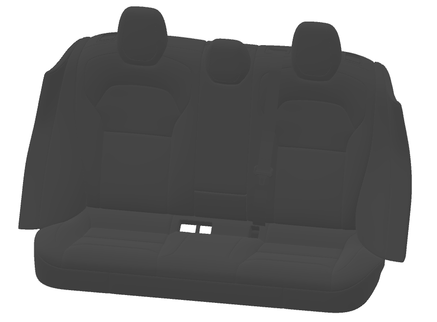
The Model 3 (2024+) has a standard five person seating capacity with a driver and passenger seat in the front row and a three passenger bench seat with fold-flat backrests in the rear. The Model 3 (2024+) Performance has a different first row seat design, but the same second row as the other variants.
 |
|---|
| Front Row Seats |
 |
|---|
| Second Row Seats |
Serviceabilitylink
The passenger seat is non-serviceable if the seat is equipped with an Occupant Classification System (OCS) that cannot be calibrated in the field. It is possible to calibrate the Model 3 front seat motors. This seat calibration routines runs each of the individual motors into their endstops, this calibrates the seat into knowing where the seat is throughout the duration of travel.
The driver seat is serviceable as it does not have an OCS but has a Seat Belt Reminder for an occupancy switch. Like passenger seat, the driver front seat can also be calibrated for all of the motors.
The first step in diagnosis should be to run the self test routines provided in Toolbox. These routines covers all motors, SBR, buckle. we also have self test to test ventilation fan connection and ALR connection. If one of these tests fail it can point towards soft set connectors or a failed component.
Coverslink
Component Descriptionlink
The seats are available in white, and black polyurethane (PUR). This material is a leather alternative.
 |
|---|
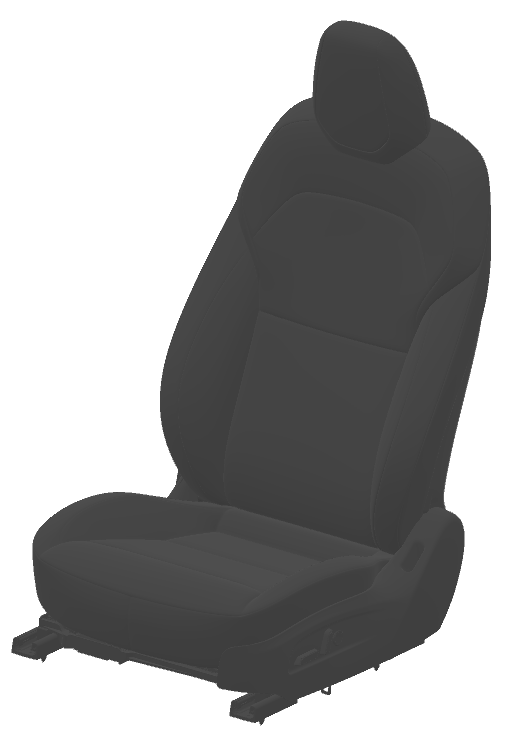
| Safety Seat Trim, First Row |
 |
|---|
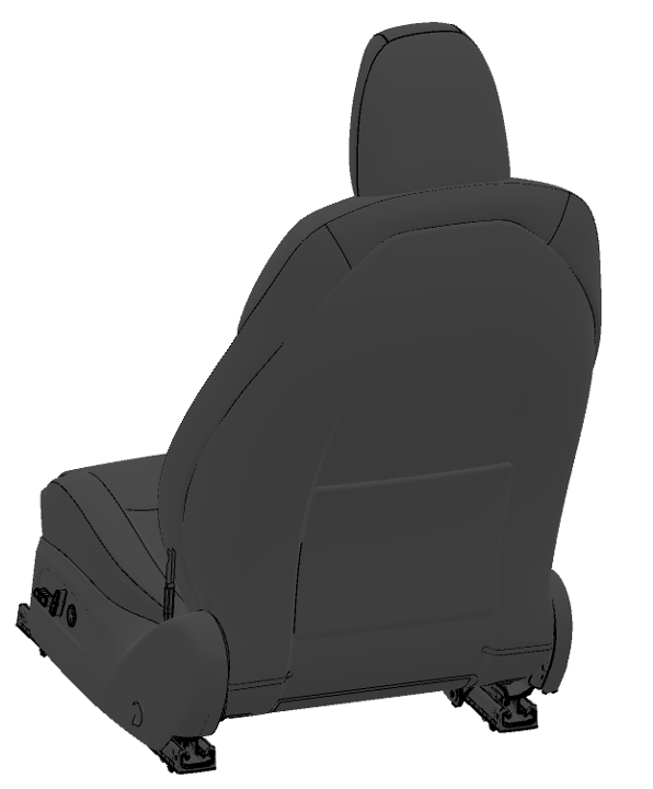
| Rear Seat Trim, First Row |
 |
|---|
| Outboard Side Shield, First Row |
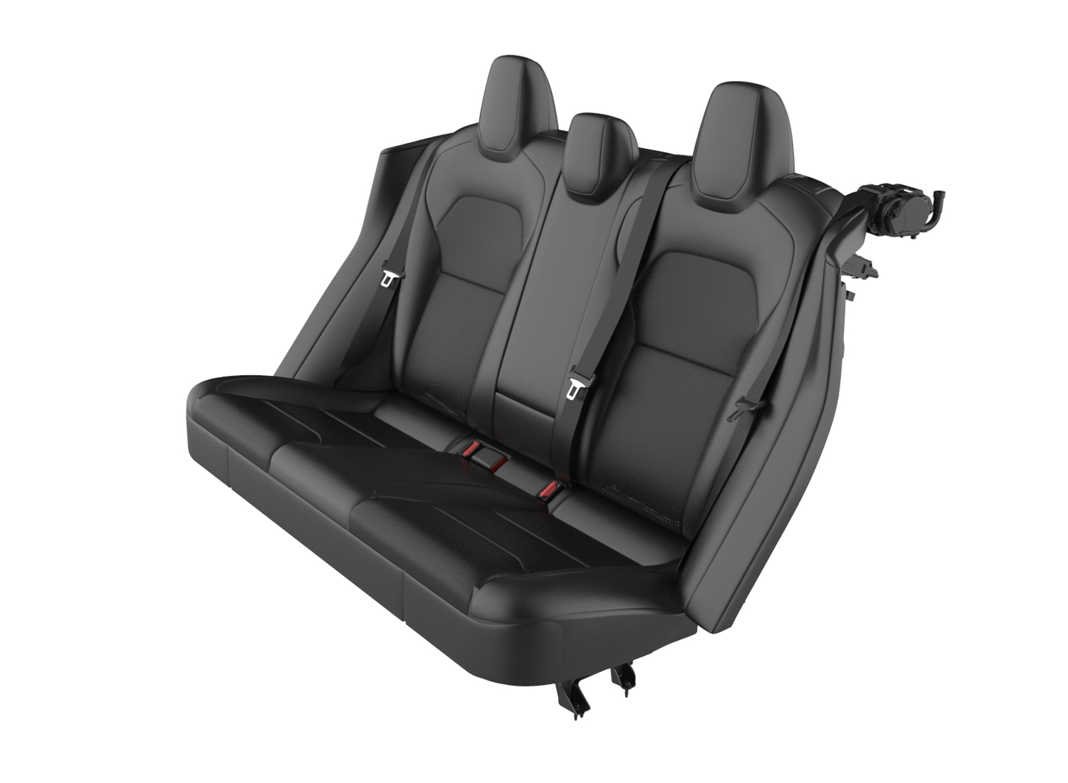 |
|---|
| Seat Trim, Second Row |
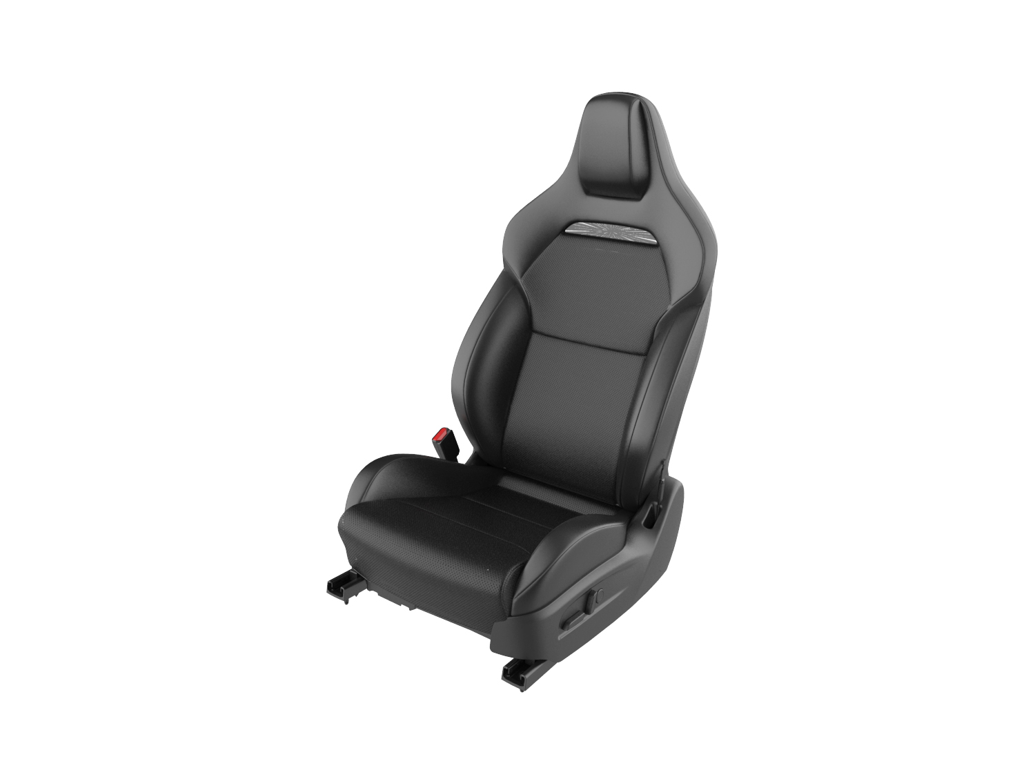 |
|---|
| Performance Variant, Driver Side |
The first row seats are perforated on the centermost panels to allow for seat ventilation. The cushion bolsters of Model 3 (2024+) Performance first row seats are stylistically split up into an inner and outer bolster. On the Model 3 (2024+) Performance, where the inner bolster meets the outer bolster, there is piping for detail and luxury. A portion of the seat cover is concealed by the outer and inner side shield. These parts of the seat cover are an anti-squeak textile material to prevent any noise concerns as the seat cushion moves through the ranges of motion. While the shape of the Model 3 (2024+) Performance AWD seats differs from the others, the functions and installation remain consistent. The passenger side seat has the similar shape as the driver side, just has the mirrored switches (but no lumbar switch which is included in the driver side) and the seat belt buckle.
Theory of Operationlink
The first row seat covers are secured to the foam with hook-and-loop fastening strips, which helps create the different panels on both the seat cushion and seat back. The seat cover is attached to the frame, enclosing the foam with various clips that are pulled taught on the frame to maintain the seat shape. The stitch detailing within the seat is used to help form the shape around the foam.
Serviceabilitylink
Cleaninglink
It is important to steam the seat covers on a low setting, quickly going over the seat cover so as to not damage components like the microphone.
Cleaning PUR seats with some conventional cleaners (especially alcohol-based) can cause performance and appearance degradation. Do NOT use products containing bleach (sodium hypoclorite). It is therefore important to clean seats with only approved cleaners. Below is a list of approved cleaners:
- Clorox NON Bleach Disinfecting Wipes
- Formula 409
- Seventh Generation NON Bleach Disinfecting Wipes
Warning
Isopropyl alcohol should not be used on Black PUR or White PUR.
Foam/Padlink
Component Descriptionlink
The seat foam, also referred to as the seat pad, provides comfort and stability to occupants.
Serviceabilitylink
If the seat foam and covers have not been properly installed it can feel or look as if the seat is missing foam or that the foam has collapsed. Because the foam is sandwiched between the cover and upholstery support, it is possible that the foam could have been misaligned during installation. In some rare cases, the way in which a user ingresses or egresses from the vehicle can apply pressure on the outmost edge of the cover and foam, causing the foam to get caught on the frame and not maintain it's full shape. This can be resolved by refitting the cover and foam.
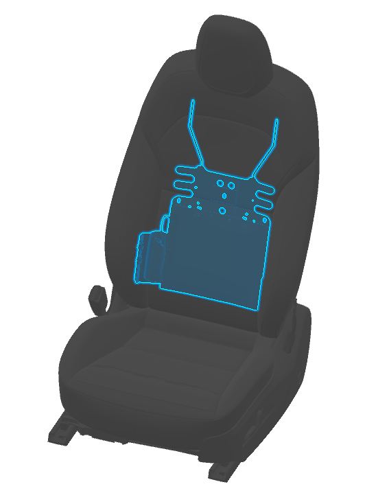
Seat Heaterlink
Component Descriptionlink
The first row has heating elements in both the seat cushion and seat back of the driver and passenger seats.
The seat heater is made up of the following components:
- High side driver
- Pulse width modulation (PWM)
- Negative temperature coefficient (NTC) thermistors
- Resistive pad
The heating element, or resistive pad, is located only in the center panels of the seat back and seat cushion, the heating element is not located in the side bolsters.
Theory of Operationlink
There are 3 heating temperature targets for the seats (low, medium and high). Target temperatures for both the cushion and the backrest are:
- Low (Setting 1): 28°C or 82°F
- Medium (Setting 2): 44°C or 111°F
- High (Setting 3): 60°C or 140°F
The seat heaters utilize Pulse Width Modulation (PWM) at 1Hz in order to reach the desired target temperature. This means pulsing the voltage at a controlled frequency. The duty cycle (width of the pulses) will be increased if the temperature read by the NTC is below the target temperature, the duty cycle can be increased all the way up to 100%, providing up to 16V. When the temperature read by the NTC is higher than the target temperature, the duty cycle can be decreased all the way to 0% providing no voltage. Due to this PWM, the voltage at the seat heater is constantly changing and varies due to ambient temperature and heat setting level.
Current travels through the resistive pad generating the heat. This resistance remains constant with a functioning seat heater.
The NTC is located only in the seat cushion, not the seat back. It is connected to 5V through a resistor on the body controller. As the temperature of the seat increases, the resistance on the NTC lowers and the voltage read at the controller goes down. If the thermistor is disconnected, the voltmeter will read 5V or 0V depending on where the disconnect occurs. At around room temperature, the voltage at the NTC should be around 3.6V.
Communicationlink
Seat heating is controlled by the left and right vehicle controllers. The seat heaters will communicate on the vehicle controller area network bus.
Auto Seat Heatlink
Auto Seat Heat is a feature where the first row seat heaters will work automatically, depending on setting temperature and actual cabin temperature. Auto Seat Heat only runs if Auto HVAC and Auto Seat Heat mode are enabled. These features are chosen via the UI. Auto Seat Heat is only for the first row seats and does not enable the rear seat heaters. The intensity of the seat heat is based off of several temperatures that from vehicle sensors as well as estimated values. Auto Seat Heat will run if the following temperature conditions are true:
| Temperature Type | Description | Threshold |
|---|---|---|
| Filtered ambient Temperature | Filtered ambient temperature based on vehicle speed | below 68F (20C) |
| Cabin Interior Temperature | Modeled interior cabin temperature | below 77F (25C) |
| Cabin Temperature Interior Sunny | Modeled interior surface temperature exposed to direct sunlight and the sky radiation | below 95F (35C) |
Monitoring these various temperature parameters determines whether the seat heater is active or not when the vehicle is already warm. The intensity of the seat heater duty cycle is a function of the cabin environment, it will start off at the maximum duty cycle and slowly come down. The relative intensity is based off the chosen set temperature of the user. The golden set temperature that this feature is modeled after is 71.6F (22C) within the cabin.
If there are any issues with the THS sensor, cabin temperature probe sensor or the ambient temperature sensor, the vehicle cannot utilize Auto Seat Heat mode. These sensors initialize the cabin temperature model to get an understanding of the cabin environment. The first row passenger seat will only enable the seat heater if there is a passenger detected in that seat.
Serviceabilitylink
The seat heater resistive pad is adhered to the seat foam and is therefore not serviceable without potentially damaging the seat foam.
The temperature felt at the surface of the seat depends on an occupant sitting in the seat. Compressing the foam and trim with an occupant sitting in the seat allows for the occupant to fully feel the temperature provided by the seat. Factors such as a heat soaked interior, body heat from someone sitting in the seat, direct sunlight, and ambient air temperatures can play a big role on the temperature readings at the surface of the seat cover.
Helpful signals for Auto Seat Heat to monitor temperatures:
- VCFRONT_tempAmbientFiltered
- VCRIGHT_cabinTempInterior
Seat Ventilationlink
The first row seats are equipped with seat ventilation in both the seat cushion and seat back. This feature is standard on the vehicle.
The seat ventilation is made up of the following components:
- Perforated seat cover PUR
- Reinforcement mesh
- Spacer mesh
- Holes within the seat heater and OCS sensor (if equipped) to matchup with the holes in the foam
- Foam
- Fan
For long range AWD, the seat cover perforation is exclusively available on the center panel. For performance AWD, the seat cover perforation is available on both the central panel and inner bolsters.
Note
The rear seat covers have perforated holes on their cushion and seat backrest to keep appearance and shape of front row seats, but they do not have seat ventilation functions.
Theory of Operationlink
Seat ventilation can be activated via the UI.
There are 3 levels of cooling. The seat cover is perforated to allow air flow at the cover A surface. Beneath the seat cover is the reinforcement mesh, this mesh is to prevent the perforated cover from cracking and tearing. There is then a spacer mesh, which allows airflow tangentially underneath the occupant. Below the spacer mesh is the heater pad and OCS sensor (if equipped). There are holes within the seat heater and OCS sensor that match up with the foam below them so as to allow for airflow. On the B side of the foam, there is a channel through the center which a plastic adapter then mates the ventilation fan, completing the path of airflow.
The fan is a suction fan and draws air through the A surface of the seat cover, because the air is being pulled instead of pushed, there is no need to chill the air. The fan has 3 wires, for voltage, ground and PWM signal. The PWM signals allows for the chosen duty cycle to set the cooling to one of the three options. The fan operates at 16V.
Communicationlink
Seat ventilation is controlled by the left and right vehicle controllers. The seat ventilation communication is on the vehicle controller area network (CAN) bus.
Framelink
Component Descriptionlink
The front seat structure is comprised of two main assemblies, the cushion assembly and the backrest assembly, which are each built separately then assembled together to form the full structure. Seats are composed of:
- A metal frame
- Electronics and wiring harnesses
- Foam cushions
- Restraint components
- Trim covers
Serviceabilitylink
The frame is typically the source of any rocking issues that can occur. During diagnosis, the joints for heigh movements, track ball bearings or recliner joints are usually place in which rocking can originate from. The cushion spring can cause certain noise concerns if not properly seated on the cushion frame.
Trim/Plasticslink
Component Descriptionlink
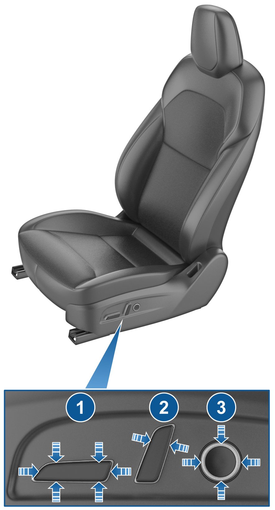 |
|---|
| 1. Seat cushion button 2. Recliner button 3. Lumbar button |
| Seat Controls, Outboard Side Shield |
Serviceabilitylink
Both the inner and outer side shields come as two pieces. This is to accommodate a slight degree of rotation difference in the seat belt buckle and the seat belt pretensioner between the North America and Europe variants.
Motorslink
Component Descriptionlink
The first row seats have a total of four electric 16V DC brushed motors that control the different seat adjustment functionalities.The front seats have the ability to move on 4 axis:
- Track: Forwards and backwards, moves the seat closer or further away from the steering wheel.
- Height: Up and down, this allows the height of the seat to be taller or shorter.
- Tilt: Up and down, this allows the front pan of the seat cushion to be taller or shorter.
- Recliner: Forwards or backwards, moves the back rest around the pivot point of the seat.
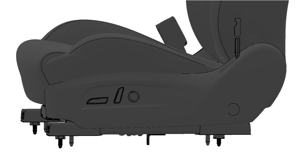
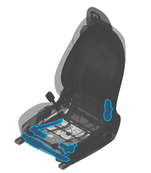 |
|---|
| Motor locations, first row |
| 1. Recliner motor 2. Tilt motor 3. Height motor 4. Track Motor |
Each front seat is equipped with a 12-way control switch pack used to manage the different seat adjustment functionalities. The lumbar control feature is exclusively available on the driver side, while seat heaters for all seats are activated via the touchscreen.
 |
|---|
| Seat Controls |
Theory of Operationlink
First row seats have a total of 4 electric 16V DC brushed motors that control the different seat adjustment functionalities. This includes track, lift, tilt, and recline adjustments.
| Motor | Nominal Current (A) | Stall Current (A) | Under Current (A) |
|---|---|---|---|
| Track | 1.3 | 22 | 0.2 |
| Lift | 0.9 | 16 | 0.2 |
| Tilt | 0.9 | 16 | 0.2 |
| Backrest | 1.3 | 12 | 0.2 |
Communicationlink
The power functions of the seats are controlled by the left and right body controllers. The left front seat is controlled by the left body controller (VCLEFT) and the right front seat is controlled by the right body controller (VCRIGHT). The rear seat functions are controlled by the left and right body controllers.
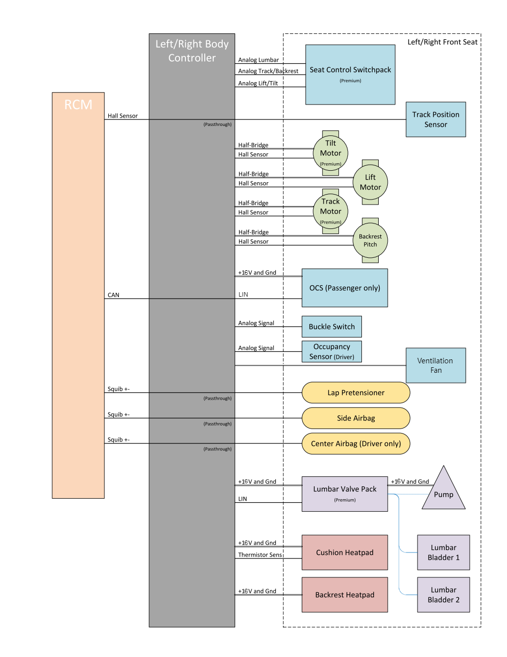 |
|---|
| Front Seats Communication Diagram (North America vehicles) |
Lumbar Support Systemlink
The front row driver's seat has lumbar system, which is a pneumatic 2-bladder, 4-way power system. It consists of an air pump, a valve pack, two air bladders and a lumbar flex mat.
Theory of Operationlink
The lumbar control unit is controlled via local interconnect network (LIN) communication by the corresponding left or right body controller. Depending on the user command via the 4-way lumbar control button on the seat, the control unit will pump or deflate the corresponding air bladders to provide the desired lumbar support. The body controller constantly monitors the pressure in each bladder using the pressure sensors in the valve control unit to keep the pressure within specified limits. There is also a blow-off valve for each bladder to release excess air once max pressure is reached.
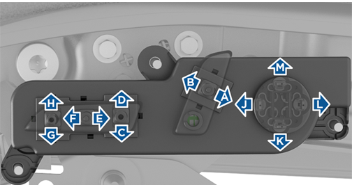
The lumbar 4-way control button has the controls:
- Up = Inflate (B1), Deflate (B2)
- Down = Inflate (B2), Deflate (B1)
- Right = Deflate (B1)+(B2)
- Left = Inflate (B1)+(B2)
The following movements are a result of pressing two functions together. The switch below the circular button has 4 different switches so pressing two together result in the following:
- Up+Right = Deflate (B2)
- Up+Left = Inflate (B1)
- Down+Left = Inflate (B2)
- Down+Right = Deflate (B1)
 |
|---|
| Lumbar Support System |
Serviceabilitylink
The body controller monitors pressure change during operation to identify a possible leak in the system. If the bladder has a leak or cannot maintain pressure, this could result in failure to calibrate.
Driver Profilelink
Feature Descriptionlink
The Driver Profile feature is the ability to save the preferred seating position of the driver. When the driver's seat, steering wheel or driver's side mirror is adjusted, the touchscreen will prompt the user to create a driver profile to save these adjustments. The driver's profile can utilize the "Use Easy Entry" checkbox if the user would like the steering wheel and seat to adjust when the park gear is engaged and the driver's seat belt is unbuckled, allowing an easy exit from the vehicle. When returning to the vehicle and stepping on the brake pedal, settings automatically adjust back to the setting used by the most recent driver profile.
The vehicle supports up to 10 driver profiles. The driver profile can be linked to keys, including authenticated phones, key cards, and up to 4 key fobs.
Theory of Operationlink
The driver's profile is recalled from the UI. When a user saves a driver's profile it is associated with an index. The UI then saves the orientation of the various motors in millimeters and degrees. There is then an app layer on the left vehicle controller which performs inverse kinematics that translates the millimeters and degrees into encoder counts on the motor.
The procedure of driver profile changes is:
- UI determine which driver profile is active, on basic of key information or customer selected driver profile
- UI sends stored target position to the vehicle controller and vehicle controller executes until target position is reached.
If profile-based seat memory recall does not appear to be functional, there are usually two failure modes: one is the desired driver profile is not loaded correctly, the other is seat fails to move to target position. For desired driver profile is not loaded, please check whether corresponding key is detected (driver profile and key information are linked together). For seat fails to move to target position, first check whether UI sends the correct target position for desired driver profile, then check whether seat reaches target position , if not, check whether alerts for potential reasons or any debris blocks movement.