Filter Selection
Select from the following air suspenion varients:
Tesla Air Suspensionlink
Last updated: October 20, 2023
Overviewlink
This document details the components, specifications, theory of operation, and relevant serviceability information of the
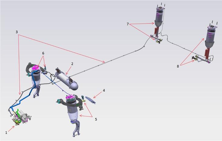
The system operates primarily by evaluating vehicle ride height through a ride height sensor at each corner suspension, then filling or exhausting air to or from the air spring at each corner. Air is compressed using the on-board compressor and stored in a reservoir.
 |
|---|
| Tesla Air Suspension System 1. Air Compressor Assembly (including Solenoid Valve Block, Air Filter and Ambient Temperature Sensor) 2. Reservoir 3. Air supply pipes 4. Air suspension Electronic Control Unit 5. Left-hand Front Suspension Module and Height Sensor 6. Right-hand Front Suspension Module and Height Sensor 7. Right-hand Rear Suspension Module and Height Sensor 8. Left-hand Rear Suspension Module and Height Sensor |
Definitionslink
| User | Definition |
|---|---|
| User | The "User" can be any person interacting with the air suspension system. This could be the driver or a passenger in typical driving conditions. It could also be a service technician during servicing of the vehicle. |
| User interface | User Interface (UI) includes all devices that allow interaction between the vehicle and its user. Most common devices that the vehicle uses to provide information to the user are various screens and speakers. Most common devices that the user uses to provide information to the vehicle (beyond the driving controls such as the steering wheel, accelerator, etc.) are touch screens and switches. |
| Mode | A mode is an operating state of the air suspension controller. The controller is always in one of predefined operating modes (ready, driving, stopping, etc.). The firmware executing on the microcontroller determines the current mode based on inputs available to it. Each mode brings up a different set of calibration parameters (height thresholds, filtering strengths, etc.) appropriate for that mode, has functional restrictions (leveling allowed or not, etc), and has a set of transition conditions on which the mode control logic can transition from it into another mode (based on inputs such as speed, etc.). |
| ECU | Electronic control unit (ECU) is an electronic hardware unit that, within its enclosure, contains a circuit board with a microcontroller. The microcontroller executes instructions of its firmware (embedded software). The microcontroller is connected to the outside of the ECU through electronic circuits which terminate at electric connectors on the outside of the enclosure. The electronic circuits condition (adjust, limit, filter, etc.) the electric input signals that arrive to the microcontroller through the connectors and they condition the output signals that go from the microcontroller to the connectors. |
| Control strategy | Control strategy is an algorithm that determines how the controller reacts to its current inputs signals to produce its output signals that achieve the desired operation. The goals of the control strategy are defined through functional requirements in this specification. Although the functional requirements in this specification often outline, suggest, and sometimes even define the control strategy, there are different detailed control strategies that could achieve those functions. The chosen control strategy could be documented in a different document (design specification for the control strategy or for the firmware). The control strategy is implemented as firmware that executes on the microcontroller which is contained within the ECU. |
| Corner | Corner refers to any of the locations at individual wheels of the vehicle and it includes the suspension and body parts above the wheel. Example: right front (RF), left front (LF), right rear (RR), left rear (LR). |
| Axle | Axle refers to a pair of corners at either the front or rear of the vehicle. Example: the front axle consists of the left front and right front corners. |
| Side | Side refers to a pair of corners at either the left or right sides of the vehicle. Example: the left side consists of the left front and left rear corners. |
| Raising | Raising is the process of the air suspension actively moving air into the air springs to cause the height of the vehicle to raise. |
| Lowering | Lowering is the process of the air suspension actively moving air out of the air springs to cause the height of the vehicle to lower. |
| Leveling | Leveling is the process of the air suspension actively moving air in to or out of the air springs to move the height of the vehicle to a target level. |
| Axle-leveling | Axle-leveling is the process of leveling a pair of corners (fronts or rears) to a target ride height. In the case of axle-leveling, the average height of the two corners is considered relative to the target ride height. |
| Target level | Target Level is the desired Level, as defined manually by the user or other automatic parameters, such as a geofenced level request or a speed-based leveling request. |
| Level definition | Level definition relates the level to a desired ride height change from the calibrated "0" point (standard). For example, the level definition for HIGH may be +20mm with respect to STANDARD = 0mm. |
| Ride height | Ride height is the height of a vehicle body location with respect to ground. |
| Calibration | Calibration is the process of determining the appropriate values for control strategy parameters (such as thresholds, time limits, sensor transfer functions, etc.) defined in this specification. Calibration is performed by engineers or technicians based on testing or measurement. Calibration includes permanently entering the determined parameters into firmware. |
| Gallery | The gallery is the air volume within the valve block. During a leveling or filling operation, the gallery may be charged, and as such gallery pressure may increase. To decrease the load on the valves in the valve block, the gallery is exhausted to ambient after most operations. |
Componentslink
Air Springslink
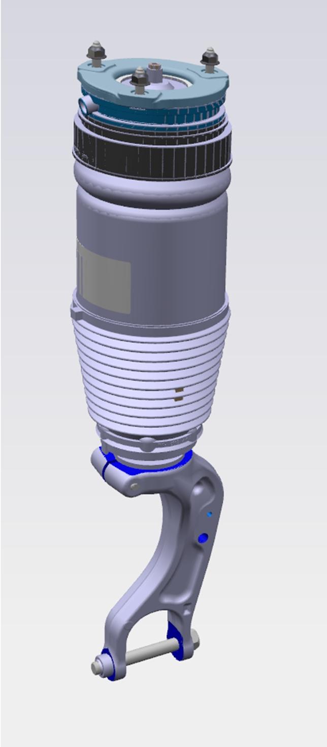
At each corner of the vehicle, there is an air spring. The air spring replaces the coil spring, supporting the load of the vehicle, while also allowing for an adjustable of ride height
 |
|---|
| Air Spring |
 |
 |
|---|---|
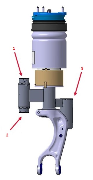
| Adaptive Front Air Spring 1. Compression solenoid valve 2. Rebound solenoid valve 3. External gas reservoir |
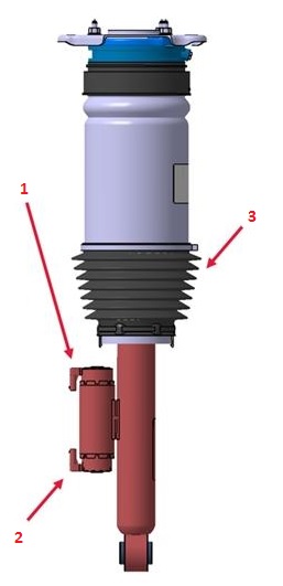
Adaptive Rear Air Spring 1. Compression solenoid valve 2. Rebound solenoid valve 3. Dust boot |
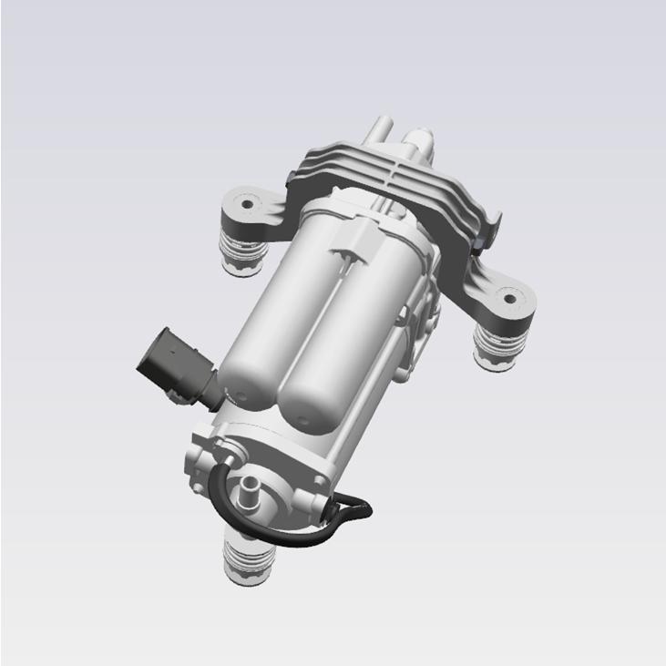
Air Compressorlink
The air compressor introduces pressurized air into the system, filling the reservoir and air springs as needed. The compressor works in two compression stages:
- The first stage raises the air pressure to approximately 8 bar (116 psi).
- The second stage raises air pressure up to approximately 18 bar (261 psi).
The compressor can use a secondary air source (the reservoir) as an input to the second stage, allowing the reservoir to raise air from 8-12 bar (116 - 174 psi) up to 18 bar (261 psi). This is known as the boost feature and is explained in this specification. The compressor is located in front of the right front wheel, behind the wheel arch liner.
 |
|---|
| Air Compressor |
The compressor is driven by an electric motor. The electronic control unit (ECU) controls the compressor run time. There is no temperature sensor to prevent the compressor from overheating. Instead, the ECU estimates the compressor temperature based on compressor run-time and ambient temperature.
The compressor and the valve block are mounted together on the same bracket. The compressor assembly houses a couple other components such as a boost valve, an exhaust valve with pilot valve and an air dryer. For detailed descriptions about the function of each of these components refer to the Pneumatic Layout section.
The unit is rubber mounted to the bracket to isolate mechanical vibration.
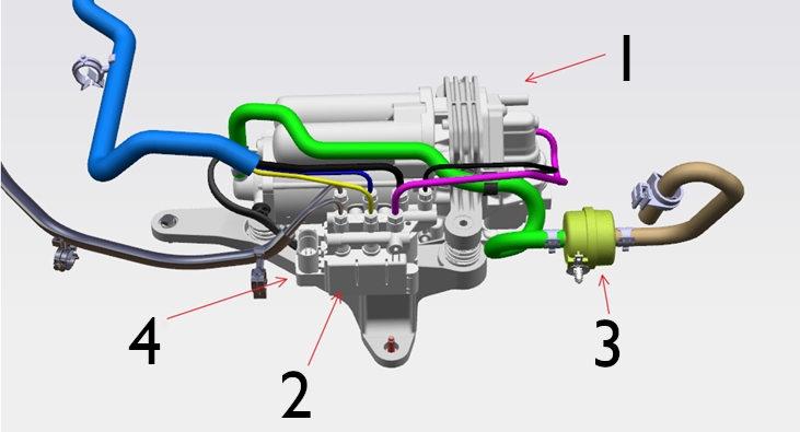 |
|---|
| Compressor / Valve block top view 1. Air compressor 2. Solenoid Valve Block 3. Air Filter 4. 2 Electrical connectors - 10 Pin for Solenoid Valve Block and 2 Pin for Air Compressor (not shown in above picture) |
| Specification | Value |
|---|---|
| Voltage range | 9-16 V |
| Maximum permanent current | 38 A |
| Operating temperature range | -40 - 120 degC |
| Operating pressure range | 0-18 bar (0-261 psi) |
Air dryerlink
The dryer is part of the compressor assembly. It consists of many silica gel granules which can absorb and release moisture out of the air. The purpose of the dryer is to absorb the moisture from the ambient air as it is sucked into the system.
For the air dryer, two situations are important:
- When ambient air is sucked into the system:
- The compressor sucks in ambient air through the inlet and pumps it through the dryer towards the valve block.
- Pressurized ambient air runs through the dryer and releases the moist to the dryer.
- The dry air enters the valve block and the reservoir.
- Second is when the dry air is vented to ambient:
- The exhaust valve switches together with one or more air spring valves and the vehicle lowers.
- Dry air runs through the dryer which allows the dryer to regenerate and be ready for the next leveling cycle.
Note
If there is a leak in the system, dry air escapes the system through the leak instead of through the exhaust valve. As a result, not all dry air runs through the dryer when lowering the vehicle. The dryer has to dry more air than it can use to regenerate. At some point the dryer becomes saturated and can no longer dry the ambient air. This is the moment where water starts to enter the system. This can quickly lead to corrosion of valves and compressor or in cold climates lead to frozen valves.
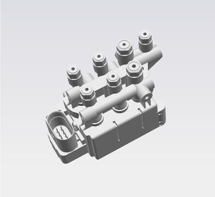
Valve blocklink
The valve block contains the air spring valves as well as the pressure sensor and reservoir valve. The valve block functions as one of the main routing controls for air flow, allowing air from different sources to enter or exit the reservoir, air springs, or compressor. The valve block also contains the only pressure sensor for the system, so all pressure measurements are taken by opening valves to expose the pressure sensor to the volume that is being measured (for example, measuring air spring pressure requires the air spring valve to be opened and the gallery where the sensor is located equalizes in pressure with the air spring).
The solenoid valve block is designed to control air flow to and from the air compressor, air suspension modules, and reservoir, then vent to the atmosphere. This is controlled by commands from the electronic control unit (ECU). The block also features a color key to assist in assembly to identify the correct air supply pipes. The valve block is located near the compressor.
 |
|---|
| Valve block |
Integrated also into this block are the following:
- Pressure Sensor - The pressure sensor measures the System Air Pressure in the gallery
- Solenoid Valves - The 5 solenoid valves are held closed by system air pressure and are operated open by the ECU to maintain the correct pressure in air spring modules of the system, according to information received from sensors or driver commands. This ensures that the vehicle is always at the correct height. These valves also control limp home modes.
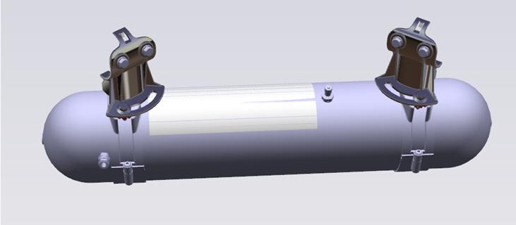
Reservoirlink
The reservoir stores pressurized air for the system to use at a later time. This allows the compressor to run at different times from raising or operations. For example, the reservoir can provide pressurized air to raise an air spring, but the compressor will fill the reservoir at a high speed where the user may not notice it. The reservoir has a maximum volume capacity of 5.2 liters and has a maximum operation pressure of 18 bar (261 psi).
 |
|---|
| Reservoir |
Whenever the tank is deflated during service it should be filled. Always refer to the Service Manual for the latest information on refilling the air suspension system. Inflating the reservoir is done using an external nitrogen cylinder. Never use shop air to inflate the reservoir as this can bring moisture into the system.
Electronic Control Unitlink
The electronic control unit (ECU) for Tesla Air Suspension is named TAS
Inputs to the ECU are:
- The 4 ride height sensors
- The pressure sensor inside the valve block
- Ambient Air Temperature Sensor
Outputs to the ECU are:
- The compressor
- The 5 solenoid valves inside the valve block
- The 4x2 solenoid valves for compression and rebound in the air springs
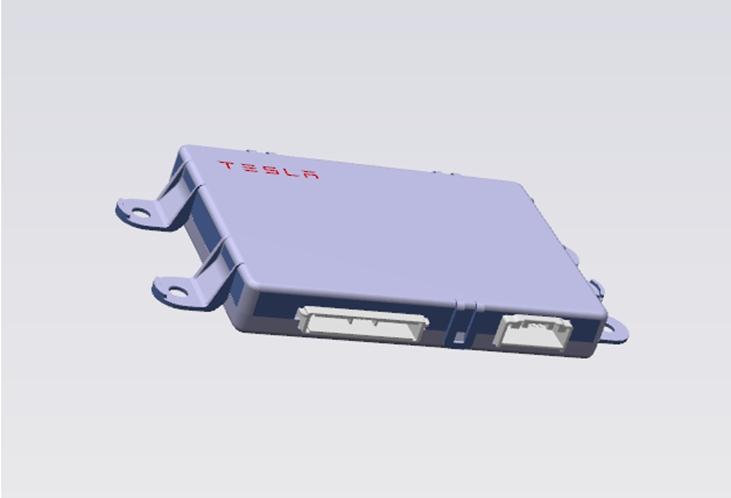 |
|---|
| TAS ECU |
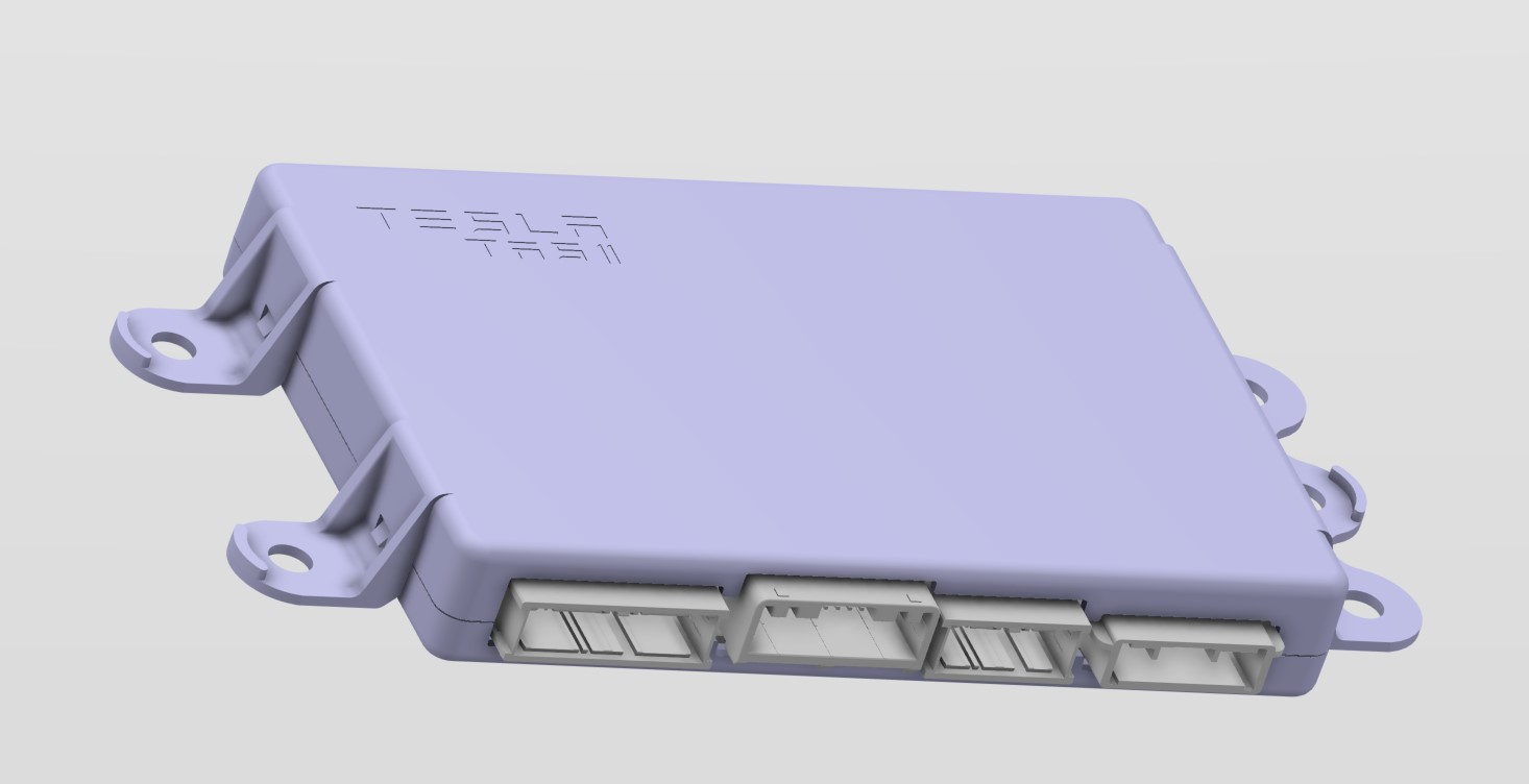 |
|---|
| TAS2 ECU |
Height Sensorslink
The contactless Hall effect sensors are fitted at each corner of the vehicle and allow the ECU to determine the ride height of the vehicle (wheel center position relative to the body). The height sensors are supplied with 5 V and send a Pulse Width Modulation (PWM) output signal to the ECU.
The 4 ride height sensors are exactly the same, only the 4 brackets are different.
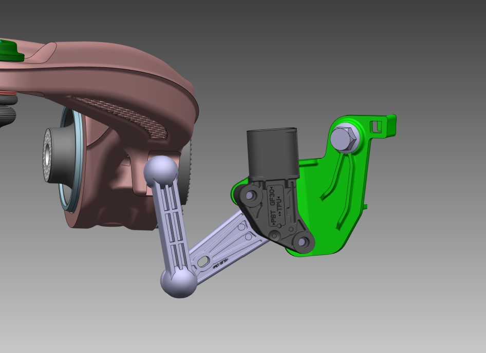 |
|---|
| Height Sensor Green - Bracket Black - Height Sensor Gray - Linkage System Brown - Front Upper Control Arm |
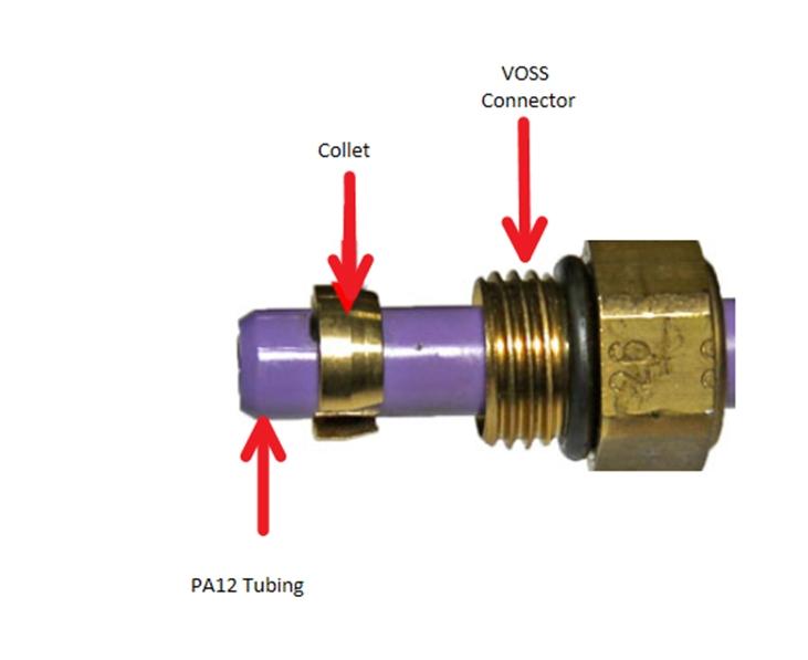
Air Supply Pipes and Fittingslink
Polyamide tubing (PA12) forms the pipe work to distribute air pressure from/to the suspension components. Air lines to the springs, compressor and the valve block are secured using VOSS 203 fittings. The air line on the reservoir is secured using VOSS 203n style fittings.
 |
 |
|---|---|
| VOSS 203 fitting installed on air springs, compressor and valve block | Voss 203n fitting installed on reservoir |
Both the VOSS 203 and the 203n are one-time use fittings. This is because the collet (VOSS 203) or the grip disk (VOSS 203n) have to be cut in order to remove the air line. New components come with pre-assembled VOSS fittings to push the existing air line in place.
Warning
Try not to install a VOSS fitting into a component with the air line still attached as it is very easy to cross-thread the thread on the component. If possible, install a new VOSS fitting first and then insert the air line.
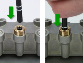
To access the collet on 203 fitting (springs, compressors, valve block) unscrew fitting from component.
To access grip disk on 203n fitting (reservoir) remove fitting from component, then separate the fitting by unscrewing the top from the base. Use pliers to remove the grip disk.
 |
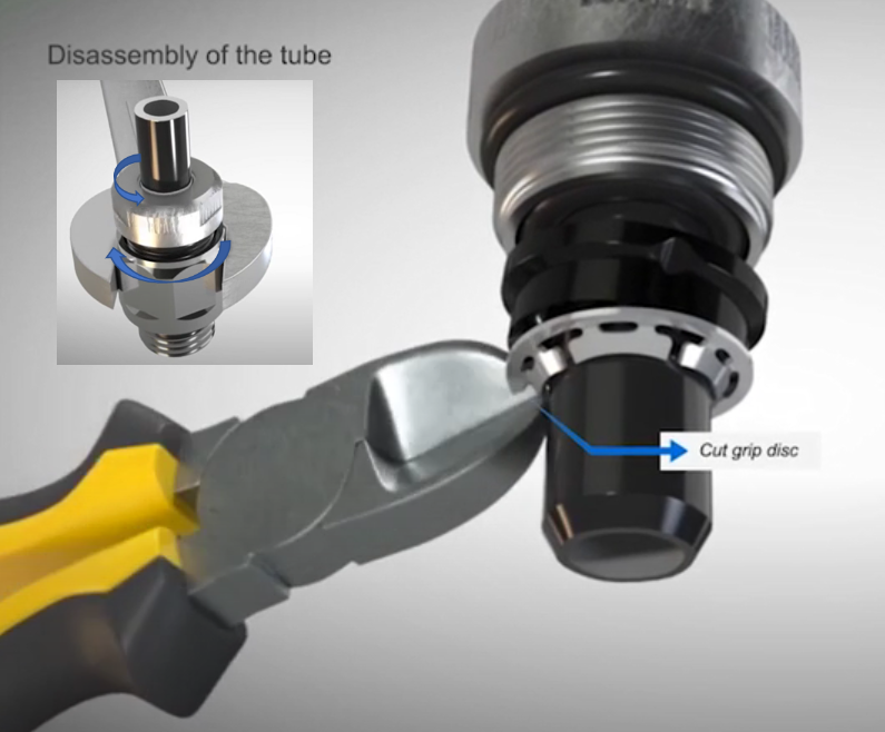 |
|---|---|
| Collet on a VOSS 203 fitting | Grip disk on a VOSS 203n fitting |
Specificationslink
| Specification | Value |
|---|---|
| Chassis height front - unladen (measured at suspension bolt) (Non-Adaptive) | 258.5 mm +5 mm / -10 mm |
| Chassis height rear - unladen (measured at suspension bolt) (Non-Adaptive) | 189 mm ± 5 mm |
| Chassis height front - unladen (measured at suspension bolt) (Adaptive) | 253.5 mm ± 5 mm |
| Chassis height rear - unladen (measured at suspension bolt) (Adaptive) | 184 mm ± 5 mm |
| Leveling rate | between 1 mm/s and 10 mm/s |
| Reservoir fill capacity | > 3 bar/minute |
| Minimum average wheel height (in normal system operation) | -40 mm |
| Maximum average wheel height (in normal system operation) | 41 mm |
| Leveling hysteresis | ±5 mm of target level |
| Maximum system pressure (seen at the reservoir) | 18 bar |
| Minimum system pressure (set by internal check valve of the compressor) | 3.6 bar |
Theory of Operationlink
This section describes how the system works if nothing is not operating as expected.
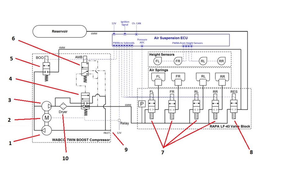
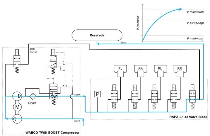
Pneumatic Layoutlink
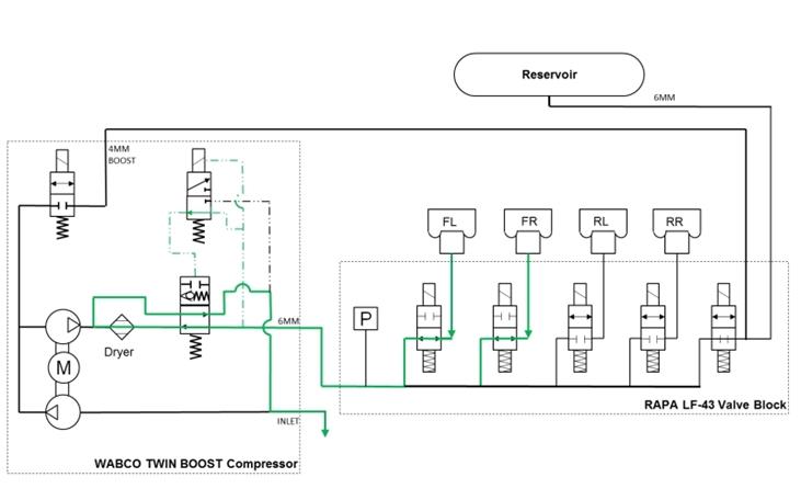
One of the most important aspects of the Tesla Air Suspension system to understand is the pneumatic layout. It shows very nicely the air flow paths by switching valves and/or running the compressor.
 |
|---|
| Pneumatic layout of the Tesla Air Suspension system 1. First compressor stage 2. Compressor motor 3. Second compressor stage 4. Exhaust valve 5. Boost valve 6. Pilot valve 7. Air spring valves 8. Reservoir valve 9. Air inlet/outlet 10. Air dryer |
Boost Valvelink
Normally closed. When opened it allows reservoir air to be fed into the second stage of the compressor. More information on the boost feature in section Fill Spring From Boost.
Pilot valvelink
The pilot valve is a small electronically actuated valve that allows gallery pressure to open the large pneumatically actuated exhaust valve. A pilot valve is used because switching the large exhaust valve electronically would require a rather high power output on the ECU. The pilot valve acts as a relay, instead it switches air instead of current.
Exhaust valvelink
The exhaust valve controls the air flow towards the valve block. When in rest, the exhaust valve allows the compressor to pressurize the valve block gallery. The path towards the inlets/outlet is cut off.
When switching the exhaust valve, it creates an air path from the valve block gallery, through the dryer to the inlet/outlet. This is used to lower springs, the exhaust the gallery or to deflate springs or the reservoir. The compressor doesn't run during this operation.
Refer to Air Management for detailed explanation about the different air paths as result of valve switching logic.
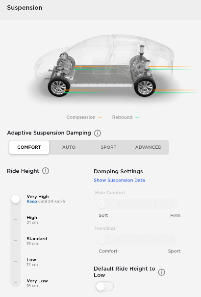
UI interactionlink
The suspension screen can be found under Controls > Suspension. The suspension panel is split into 4 main sections:
- Ride Height
- Adaptive Suspension Damping
- Damping Settings
- Default Ride Height to Low
 |
|---|
| User Interface of the air suspension system Note: picture might look different due to firmware updates. |
 |
|---|
| User Interface of the adaptive air suspension system Note: picture might look different due to firmware updates. |
The air suspension system can also show a yellow or red indicator light on the center display. A yellow light indicates a temporary fault, or one that does not require immediate servicing of the vehicle. A red light indicates that the fault that needs immediate attention. When a fault occurs, the vehicle enters a limp home mode.
Ride height (leveling)link
The target level can be decided based on a number of factors: user selection from UI, vehicle speed, GPS position, etc.
The UI allows for manual selection of all available levels. Some levels are made temporarily unavailable due to external conditions or system faults. The unavailability is enforced by both the UI and the system. Some levels are permanently unavailable, depending on the vehicle type. Permanent unavailability is enforced by the UI, it is not enforced by the system.
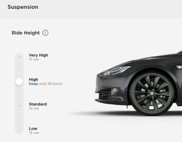
The driver can select from four height levels using the touchscreen. Click on the Controls > Suspension.
Note
The VERY LOW setting is not visible to the user.
| Level | Height | Maximum speed |
|---|---|---|
| Very high | +35 mm | 56 km/h (35 mph) |
| High | +20 mm | 72 km/h (45 mph) |
| Standard | 0 mm | - |
| Low | -20 mm | - |
| Very low (not available to user) | -35 mm | - |
Very highlink
When the ride height is set to VERY HIGH level, the suspension automatically lowers to the default ride height after driving approximately 30 m (100 ft) or when driving faster than 56 km/h (35 mph).
It is possible to maintain the very high ride height for an unlimited distance by selecting 'Keep until 24 km/h'. Only after exceeding 24 km/h (15 mph), the vehicle will lower to HIGH ride height.
Highlink
When the ride height is set to HIGH level, the suspension automatically lowers to the default ride height after driving approximately 30 m (100 ft) or when driving faster than 72 km/h (45 mph).
It is possible to maintain the HIGH ride height for an unlimited distance by selecting 'Keep until 56 km/h'. Only after exceeding 56 km/h (35 mph), the vehicle will lower to standard ride height.
Standardlink
The STANDARD ride height is considered the neutral ride height of the vehicle meaning ride height levels are close to 0 mm. The vehicle is in STANDARD ride height when performing service routines such as Ride height calibration or a 4 wheel alignment.
Lowlink
The LOW ride height can improve the aerodynamics and can make it easier to load or unload cargo and passengers.
Geofence radiuslink
Tesla Air Suspension uses a geofence radius to lower the vehicle to it's default ride height after HIGH or VERY HIGH ride height was selected by the user. This geofence radius as an imaginary circle of 30 m (100 ft) around the point where the ride height was set to HIGH or VERY HIGH.
Default ride heightlink
Tesla Air Suspension automatically adjusts to a default ride based on driving speed. The default ride height can be set to STANDARD or LOW.
Automatic loweringlink
As mentioned under ride height levels VERY HIGH and HIGH, the vehicle automatically lowers to the default ride height when exceeding the speed limit for that particular ride height. At higher driving speeds, the handling and aerodynamics of the vehicle are much better in lower suspension heights.
Automatic raisinglink
Whenever the customer raises the suspension to HIGH or VERY HIGH, they can select 'Always Auto-Raise at This Location' to save the location. When they return to the saved location, Tesla Air Suspension raises the suspension and the instrument panel displays a message indicating that the suspension is being raised.
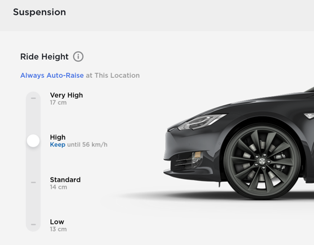 |
|---|
| User Interface showing the option to 'Always Auto-Raise at This Location' when leveling to high or very high ride height |
The location is stored in the UI. Next time the vehicle enters the geofence location, the UI sends a message to the Tesla Air Suspension ECU, also sending the associate height. TAS(2) will automatically level the vehicle to the desired ride height. A geofenced location can be removed by the user by tapping the 'X' on the UI.
 |
|---|
| Instrument cluster message to show the user that automatic raising is active |
Leveling restrictionslink
Target levels other than the current target level are unavailable when any of the following are true:
- Raising closure restrictions are active (higher heights only)
- Lowering closure restrictions are active (lower heights only)
- TAS(2) has completed leveling in preparation for launch mode
- Jack Mode is active
- Service Mode is active
- Drive Rail is not on
- System Check is active
- System is in Limp Home Mode 40
- Vehicle has a charge cable connected via charge port.
Target levels higher than the current target level are unavailable when Limp Home Mode 30 (alert TAS2_a217_limpHomeMode30) is active. All levelling actions are unavailable when Limp Home Mode 40 (alert TAS2_a217_limpHomeMode40) is active.
Closure restrictionslink
Closure restrictions help prevent possible damage done to the vehicle by raising or lowering with doors open. If a closure is opened during a raising or lowering operation, the operation will be paused until the closure is closed. The following closures restrict leveling when not closed:
- Front Doors - Lowering Disabled
- Rear Doors - Lowering Disabled
- Lift Gate - Raising Disabled
Closure restrictions are honored at speeds below 16 km/h (10 mph). If closures state is unknown, it is treated as closed.
- When ride height is not calibrated, there will be no closure restrictions.
- While in service mode, there will be no closure restrictions.
Lean Detectionlink
Lean describes vehicle attitude side to side and is calculated from corner ride height values. Lean is detected when the corner ride height values (FL+RL) - (FR+LR) > 15 mm.
When lean is detected and not twist, the Tesla Air Suspension ECU will initiate corner leveling to bring all air springs back to the correct ride height. First, TAS(2) will evaluate which side of the vehicle that is higher, by comparing ride height values between the left and right sides of the vehicle. The side with the higher total is considered to be higher.
Example 1: If the right side is higher, corner leveling will operate on the corners of the vehicle in the following order:
- If RL is lower than the axle leveling start threshold for the current mode, raise RL until it is within the stop threshold for the current mode, or until lean is no longer detected.
- If FL is too low (as above), raise FL.
- If FR is too high (as above), lower FR.
- If RR is too high (as above), lower RR.
Example 2: If the left side is higher, corner leveling will operate on the corners of the vehicle in the following order:
- If RR is lower than the axle leveling start threshold for the current mode, raise RR until it is within the stop threshold for the current mode, or until lean is no longer detected.
- If FR is too low (as above), raise FR.
- If FL is too high (as above), lower FL.
- If RL is too high (as above), lower RL.
Note
Corner leveling is not allowed as long as no ride height calibration has been performed.
Twist Detectionlink
Twist refers to a vehicle condition where wheels on two opposing corners of the vehicle are lower, as if the chassis is being twisted. Twist is calculated from corner ride heights to determine when to restrict corner leveling (FL+RR) - (FR+RL) > 20 mm. Corner leveling is restricted when twist is detected
Note
Twist can be a result of incorrect ride height measurement, for example if a ride hide sensor bracket is bend.
Crash detectionlink
Whenever the Restrain Control Module (RCM) detects a crash, it notifies Tesla Air Suspension with a CAN signal. As a result, TAS(2) enters Limp Home Mode 40 and sets an alert to indicate that its features are disabled. When the crash event flag is cleared in service, TAS(2) exits Limp Home Mode 40.
Jack modelink
Before jacking the vehicle to change a wheel or lifting the vehicle on a hoist, Jack mode must be selected on the touchscreen via Controls > Service > Jack Mode. Selecting Jack mode can only be done when the vehicle is stationary and in Park. Jack mode turns the Tesla Air Suspension Leveling off, which allows the user to safely jack up the vehicle without the vehicle trying to adjust its height. Once the jacking procedure is complete, Jack mode can be switched off using the touchscreen. The vehicle automatically exits Jack mode when driven above 7 km/h (4 mph).
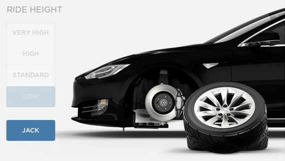 |
|---|
| UI showing Jack mode disabled ride height adjustment. The height controls is grayed-out |
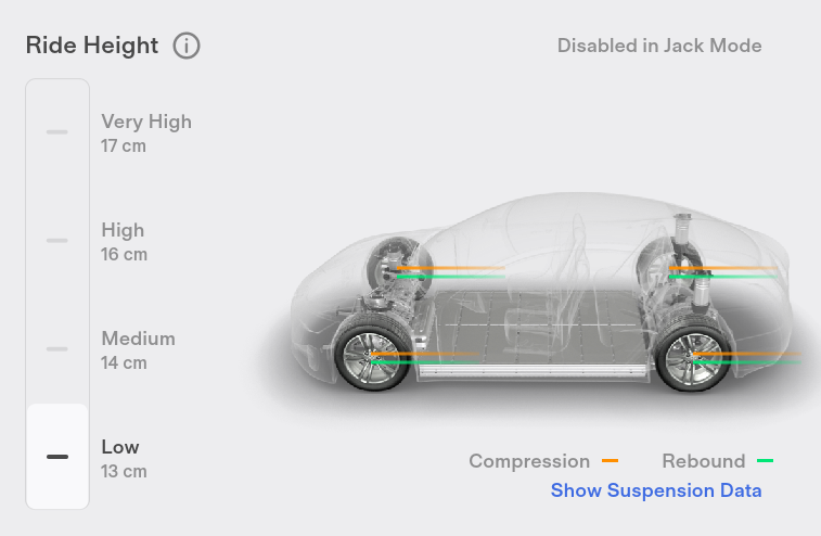 |
|---|
| UI showing Jack mode disabled ride height adjustment. The height controls is grayed-out |
Jack Mode is also activated automatically if the ECU detects that the vehicle is unable to lower to its target/selected height or that it is being supported. When Jack mode is active, all leveling is disabled.
Air Managementlink
Air management is the control strategy that TAS(2) uses to move air from one component to the other in such a way that the customer notices it the least. For example, TAS(2) will always try to raise the vehicle without running the compressor at the same time.
Reservoir Pressure Check and Pressure Measurementlink
The reservoir pressure is an important value for TAS(2) to operate. Based on the reservoir pressure it will decide how it inflates struts. For this reason the reservoir pressure is measured regularly.
The first measurement is taken 2 seconds after the ECU wakes up. Then each 30 minutes the reservoir pressure is measured again for as long as it is awake. When asleep the reservoir pressure will not measured.
It is important to measure a stable reservoir pressure. The reservoir pressure is considered stable if the measured pressure remains in a ± 50 mbar window for 50 ms with the reservoir valve open or if TAS(2) is measuring the reservoir pressure for 1 full second, in which case the last 50 ms of data will be averaged and used as the pressure reading.
Reservoir pressure is considered not valid / invalid / expired if the reservoir pressure has not been checked within the timeout time or if the reservoir valve is open with another valve open, since the pressure sensor cannot measure just the reservoir pressure.
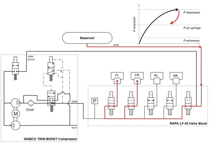
Filling reservoirlink
This section describes auto-filling behavior, in which the system detects low reservoir pressure and begins to fill. Auto-filling happens as much as possible whilst driving to make sure the user will not notice it.
 |
|---|
| Air path when filling reservoir |
Auto-filling whilst driving works according to below thresholds.
- If vehicle speed is greater than 80 km/h (50 mph), the reservoir will start filling if reservoir pressure is 17 bar or less.
- If vehicle speed is between 40 and 80 km/h (25 and 50 mph), the reservoir will start filling if reservoir pressure is 15 bar or less.
- If vehicle speed is between 16 and 40 km/h (10 and 25 mph), the reservoir will start filling if reservoir pressure is 8 bar or less.
- If vehicle speed is between 0 and 16 km/h (0 and 10 mph) and reservoir pressure drops below 8 bar, the reservoir will start filling and stop filling at 18 bar.
Other conditions that affect auto-filling:
- If the system finishes filling a spring from boost and reservoir pressure is between 8 and 12 bar, the reservoir will start filling and stop filling at 18 bar - unless the vehicle is at very high, in which case it should not fill.
- If vehicle speed falls below 16 km/h (10 mph) and filling is active, filling will stop at 8 bar.
- If vehicle speed remains above 16 km/h (10 mph) and filling is active, filling will stop at 18 bar.
- If vehicle is at very high when the vehicle exceeds 40 km/h (25 mph), filling will be delayed until after the vehicle re-levels to high ride height (or lower).
- If one or more springs are requested to raise during a reservoir fill, the vehicle will be raised and the system will then resume filling the reservoir without stopping the compressor.
- While in service mode, if reservoir pressure is too low to raise the vehicle, then raising will require compressor run. In this case, the compressor will run only as needed for the leveling operation, then stop. The compressor will not continue to run to fill the reservoir while ins service mode.
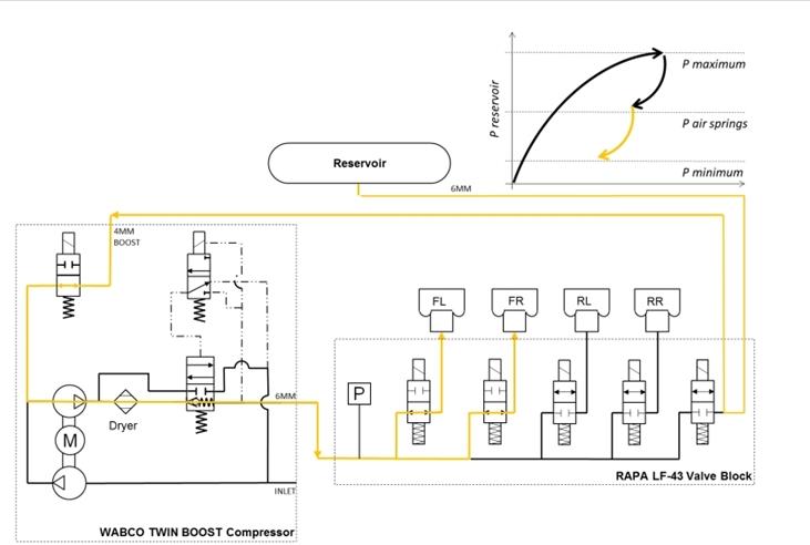
Fill spring(s) from reservoir (reservoir pressure > 12 bar)link
The compressor will use pressurized reservoir air to inflate the air springs. The pressure in the reservoir is high enough to raise the vehicle without boosting the pressure with the compressor.
 |
|---|
| Air path when raising spring from reservoir |
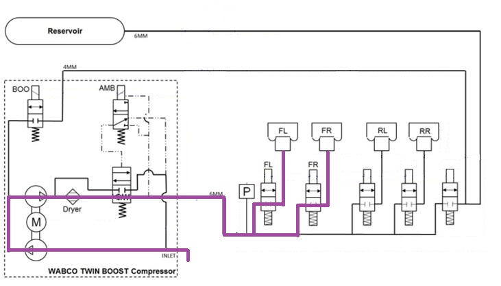
Fill spring(s) from boost (reservoir pressure = 4-12 bar)link
The compressor will use pressurized reservoir air as an input to aid in raising speed. The compressor will use the second stage to further compress the air before it flows into the air springs.
 |
|---|
| Air path when raising spring from boost |
Fill spring(s) from compressor (reservoir pressure = 0-4 bar)link
The compressor will use ambient air to raise the air springs. This is only done when then the reservoir is almost empty.
 |
|---|
| Air path when raising spring from compressor |
Deflating spring(s) to ambientlink
The system will deflate to ambient when lowering the air springs.
 |
|---|
| Air flow path when lowering the front axle to ambient |
Adaptive Suspension Dampinglink
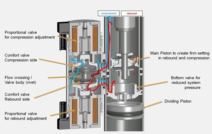
Each air spring contains a fixed primary oil flow path that is internal to the damper. In addition, the dampers have a secondary, external oil flow path, which can be controlled in real time by electric solenoids. Rebound damping (wheel moving down from vehicle body) and compression damping (wheel moving up toward vehicle body) are controlled independently. As damping only resists motion – it cannot create force without motion. Adjusting damping does not move the vehicle up or down, it just affects how much resistive force the damper applies as the wheels move up and down relative to the body.
 |
|---|
| Cross section of adaptive damper and solenoids |
Note
The valve shown here has slightly different construction from ours, namely with respect to the spring and solenoid plunger.
The adaptive air suspension system can be set to 4 different settings:
- COMFORT: provides a gentler ride for a relaxed driving experience
- AUTO: adjusts to a wide range of roads and driving styles, providing a fluid yet well controlled ride.
- SPORT: provides a firmer, more controlled ride that increases driver engagement and connection to the road.
- ADVANCED: Fine tune the suspension by dragging individual sliders to adjust Ride Comfort and Handling.
Note
Air suspension checks air spring pressure to estimate vehicle mass and adjust damping control accordingly.
Solenoid Valve Controllink
Each solenoid valve is pulse width modulation (PWM) controlled. By controlling the PWM voltage, the current through the solenoids is controlled. Current through the solenoid is inversely proportional to the oil flow through the solenoid. The higher the PWM voltage, the smaller the oil flow. This means that 100% PWM signal corresponds to a completely closed solenoid and therefore to a very stiff damping behavior. Also 0% PWM signal corresponds to a completely open solenoid and therefore to a very soft damping behavior.
Note
This means that when a solenoid valve connector is loose, or the wiring is compromised the damping behavior will be very soft, but even in this condition the vehicle is safe to drive and is completely controllable.
Continuous Controllink
Continuous control refers to “full state” damping. When continuous control is active, the system is functioning normally. Continuous control relies on multiple inputs to be fully functional (for example, height sensors, required CAN signal inputs, etc.).
End Stop Protectionlink
Tesla Air Suspension ECU uses ride height sensors to learn the distance to end of travel as the vehicle drives and encounters bumps and dips. Learned end stops are reset when Ride height calibration is performed. As the damper approaches the end of travel, damper current is increased to make the damper stiffer and to soften the impact of bottoming or topping out.
Quiet Exhaust Functionlink
Whenever each of the 5 valves (4x air spring or 1x compressor) was closed after a corner was raised/lowered or after the reservoir was filled, the gallery is still under pressure. To release the pressure from the gallery when Tesla Air Suspension ECU goes into IDLE state, the air inside the gallery needs to be vented to ambient, much like a normal shop air compressor. Especially when the reservoir has been filled, the gallery pressure can be as high as 18 bar. Exhausting directly to ambient would occur with a pretty loud and undesired hissing sound. Therefore exhausting happens in 2 stages, called 'Quiet exhaust'.
Quiet exhaust reduces the gallery pressure after the reservoir has been filled, to reduce the noise when exhausting the gallery to atmosphere. After filling the reservoir, the front spring valves are opened for 0.5s and the gallery pressure is bled into the front air springs. Then, the gallery is exhausted normally.
Quiet exhaust will be disabled when:
- Jack mode is detected.
- In service mode.
- Ride height sensors are un-calibrated.
Sleeplink
The gateway can command the electronic control unit (ECU) to stop transmitting controller area network (CAN) messages. This happens when the gateway wants the vehicle to go to sleep. The ECU automatically goes to sleep when it sees no CAN traffic for 5 seconds. When the ECU is asleep it no longer sends CAN messages. Whenever the ECU needs to perform a filling or leveling operation, it needs to wake the CAN bus in order to enable logging. The ECU transmits a 'keep bus awake' signal if the CAN bus needs to stay awake while TAS(2) is filling or leveling.
Serviceabilitylink
Service routineslink
TAS service modelink
In order to perform any of the service routines, TAS(2) needs to be in Service Mode. Service Mode can be entered and exited using Toolbox.
Calibrate Air Suspensionlink
During the ride height calibration process, a correction value (offset) for each of the four sensors is calculated and stored permanently in the TAS(2) ECU’s Electrically Erasable Programmable Read Only Memory (EEPROM). A "perfect" vehicle that matches CAD exactly would have ride height sensor offsets of 0 mm. In reality, each corner may need a small sensor offset to have the ride height sensor reading equal the physical vehicle ride height.
Performing a ride height calibration is required when removing or replacing height sensors, after changing the TAS(2) ECU, when performing repairs on the suspension or before a wheel alignment.
Ride height calibration of the vehicle height must be performed at STANDARD ride height on a 4-wheel alignment lift. Before a ride height calibration, confirm the wheel type and check the tire pressures. Always refer to the Service Manual for the latest information on ride height specifications.
Once wheel type and tire pressures are confirmed, the vehicle has to be raised to HIGH ride height and then lowered to STANDARD ride height. By doing this, the vehicle will try to level all 4 corners to 0 mm (STANDARD). It is, however, unlikely that it is able to exactly level every corner to 0 mm. Therefore, the leveling operation has a tolerance of ± 5 mm and is considered successful once all ride heights are within this window.
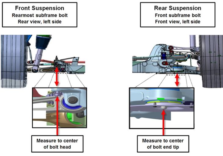
Physically measure the actual ride height between the ground (4-post lift) and the bottom of the chassis at pre-selected points (see figure below). These heights should be entered in Toolbox.
 |
|---|
| Measurement points for ride height calibration |
Toolbox sends the 4 measured ride height values to the vehicle. Using this the vehicle will calculate a new ride height sensor offset value for each corner. These offsets are used to compensate for measurement errors due to tolerances and other variations allowing the vehicle to more accurately relate the ride height sensor values to the actual ride height. This process is called 'ride height calibration'.
Example: Vehicle levels from any starting point to HIGH and then to STANDARD. It ends at the following ride heights (all nicely within the ±5 mm window):
| Current Offset | Technician Ride Height Measurement | TAS Ride Height Measurement | |
|---|---|---|---|
| FL | -2 mm | 261 mm | 3 mm |
| FR | -9 mm | 257 mm | -2 mm |
| RL | -9 mm | 188 mm | 0 mm |
| RR | -6 mm | 192 mm | 2 mm |
The vehicle will calculate new offsets using the following equation:
New Offset = Current Offset + Tech Measurement - (Spec + Level)
- 'New Offset' is the new ride height sensor offset.
- 'Current Offset' is the currently in use ride height sensor offset. These can be found using the read ride height calibration routine in Toolbox.
- 'Tech Measurement' is the ride height measurement taken by the technician.
- 'Spec' is the ride height specification as listed in the Service Manual.
- 'Level' is the current ride height as measured by TAS(2) which can be found in ServiceUI or the CAN Viewer.
| The new ride height sensor offsets | |
|---|---|
| FL | -2 + 261 - (258.5 + 3) = -2.5 mm |
| FR | -9 + 257 - (258.5 + -2) = -8.5 mm |
| RL | -9 + 188 - (189 + 0) = -10 mm |
| RR | -6 + 192 - (189 + 2) = -5 mm |
Using the FL as an example (the same can be applied to the other corners): Tesla Air Suspension ECU has positioned the vehicle at 3 mm as seen on ServiceUI or Can Viewer and thus thinks that the physical ride height is equal to 261.5 mm (spec + level). However, the vehicle was measured by the technician to be at a physical height of 261 mm. This difference in height measurements (equaling -0.5 mm) needs to be added to the current offset of -2 mm to compensate for that error. So, the new ride height sensor offset for FL is -2.5 mm.
The ride height calibration will be rejected, and the previous offsets will be restored if any of the newly computed offsets deviate more than 50 mm from the default offsets (0 mm). The ride height calibration will fail if any of the newly computed offsets deviate more than 25 mm, but less than 50 mm from the default offsets. In this scenario the offsets will be stored to iteratively improve the ride height calibration.
A sensor offset deviating more than 25 mm from default may indicate a hardware issue. Use Toolbox to diagnose the root cause of the deviation. The ride height will need to be recalibrated once the cause of the deviation is resolved.
The new ride height calibration needs to be checked once the ride height calibration routine has passed. The vehicle once again has to be raised to HIGH ride height and then lowered to STANDARD ride height. This is then followed by again physically measuring the actual ride height between the ground (4-post lift) and the bottom of the chassis at the pre-selected points. Toolbox will send these four values to the vehicle through the check ride height routine. Here the TAS(2) ECU will compare the physical measurements to its own measurements. If the physical measurements and the TAS(2) measurements deviate less than 5 mm from one another the check will pass indicating that the ride height has been calibrated successfully. If it returns a failure the vehicle's ride height has to be recalibrated.
Read ride height calibration valueslink
This routine will request TAS(2) to send the 4 ride height sensor offsets and display them in Toolbox. This allows service to check the current ride height calibration offsets.
Reset ride height calibration valueslink
This routine clears the 4 ride height calibration offsets. Until a new ride height calibration is performed, TAS(2) will use its default offset values (see table below) for all corners.
| The default ride height sensor offsets | |
|---|---|
| FL | -2 mm |
| FR | -9 mm |
| RL | -9 mm |
| RR | -6 mm |
Clear crash flaglink
This routine clears the flag that is set by the RCM after a vehicle was in a crash, see Crash Detection. When the crash flag is cleared, TAS2 will be operational again.
Deflate componentslink
This service routine allows service to deflate components of the air suspension system. Tesla Air Suspension ECU can deflate individual components or combinations of components to allow for easy service.
- Front Left Spring
- Front Right Spring
- Rear Left Spring
- Rear Right Spring
- Reservoir
- Front Axle
- Rear Axle
- All Springs
Running the deflate function in Toolbox initiates a procedure to reduce the air pressure to the selected component. Deflate function will complete when the pressure has reduced to below a preset value or when it exceeds timeout length.
- Inflation/Deflation timeout set 90 sec.
- If deflating the Reservoir, TAS(2) will not enable inflation into the Reservoir until ECU reset.
- Front springs will exhaust to 3 ± 0.5 bar.
- Rear springs will exhaust to 4.5 ± 0.5 bar.
- The reservoir will exhaust to 4 ± 0.5 bar.
Inflate componentslink
This service routine allows service to inflate components of the air suspension system. TAS2 can deflate individual components or combinations of components to allow for easy service.
- Front Left Spring
- Front Right Spring
- Rear Left Spring
- Rear Right Spring
- Reservoir
- Front Axle
- Rear Axle
- All Springs
Running the inflate function in Toolbox initiates a procedure to increase the air pressure in the selected component. Inflate function will complete when the pressure has reduced to below a preset value or when it exceeds timeout length.
- Inflation/Deflation timeout set 90 secs.
- Front springs will inflate to 8 ± 0.5 bar.
- Rear springs will inflate to 4 ± 0.5 bar.
- The reservoir will inflate to 15 ± 0.5 bar.
Measuring pressureslink
This service routine allows service to measure the pressures in all air springs and the reservoir. Running the measure pressure routine will initiate a procedure to sequentially read pressure from each suspension module and the reservoir. The only pressure sensor in the system is located in the valve block gallery. To measure all 5 pressures, each valve is opened for a short period of time to expose the pressure sensor to the volume that is being measured.
For example, measuring air spring pressure requires the air spring valve to be opened and the gallery where the sensor is located equalizes in pressure with the air spring. After the valve is opened, Tesla Air Suspension ECU waits for the pressure to stabilize, records the pressure, and closes the valve. This sequence repeats 5 times until all 5 pressures are read. The entire routine completes in less than a second. After recording the pressure reading for all 5 components, the results are reported for display in Toolbox.
- Air Spring Front Left
- Air Spring Front Right
- Air Spring Rear Left
- Air Spring Rear Right
- Reservoir
Levelinglink
The air suspension leveling function in Toolbox allows the direct selection of all available ride heights, including very low.
Warning
Door latch signal are ignored in this mode so the vehicle will lower if requested by Toolbox or touchscreen, even if the door is open.
Limp home modelink
Tesla Air suspension does not use diagnostic trouble codes (DTC). Alerts are used as the primary diagnostic tool and are recorded in vehicle logs to ease diagnosis. Below are some of the fault conditions detected by the ECU:
- Voltage supply high or low
- Valve circuit shorts or opens
- Sensor circuit shorts or opens
- Ride height sensor PWM problems
- Air compressor duty and temperature high
- Communication-related issues
Tesla Air Suspension operating restrictions are controlled by active alerts. Each alert has a Limp Home Mode (LHM) associated with it. When the alert is active, the corresponding LHM is set. If there are multiple alerts active, the system enters the most restrictive LHM.