eCalllink
Last updated: February 28, 2024
eCall is an initiative of the European Commission, its aim is to deploy a device in all new vehicles that will automatically dial the emergency services in the event of a serious road accident.
Note
eCall is only available on Tesla vehicles that are sold in Europe.
New vehicle models introduced to the European market after April 2018 are required to be equipped with eCall. In order to be compliant with EU regulations, eCall is a standard safety feature for Model 3 sold in Europe.
European Model 3 vehicles built before October 2020 are equipped with a physical eCall SOS button and backup eCall cellular antenna.
European Model 3 vehicles built after October 2020 have their eCall manual button displayed on the touchscreen User Interface (UI), without the need of a backup eCall cellular antenna.
 |
|---|
| ISO eCall Icon |
Vehicle Configurationlink
The eCall functionality depends on the configuration of the vehicle. Below are the available eCall configurations:
- Vehicles that do not have eCall enabled
- Vehicles with Front Overhead Console (FOHC) physical SOS eCall button
- Vehicles with touchscreen UI SOS eCall button
The eCall system can be configured in one of two ways:
- Vehicle is equipped with backup antenna for eCall
- Vehicle uses primary antenna for eCall
Functional Overviewlink
The system can simultaneously create:
- A data connection over which a Minimum Set of Data (MSD) is transmitted.
- A two-way voice call to locally appropriate Public-Safety Answering Point (PSAP).
Emergency Call Activationlink
The are two methods to activate eCall:
- Manual activation initiated by pressing the SOS button on the Front Overhead Console (FOHC) or on the UI.
- Automatic activation initiated by the Restraints Control Module (RCM) during airbag deployment.
Manual eCall Activationlink
Examples emergency situations where it is appropriate, but are not limited, to trigger a eCall:
- When vehicle occupant has witnessed a road traffic collision and needs to report the incident.
- When vehicle occupant requires emergency medical assistance or needs to report a witnessed medical emergency.
In the case of manual activation:
-
The user briefly presses (minimal 100ms) the SOS button on the UI or on the FOHC.
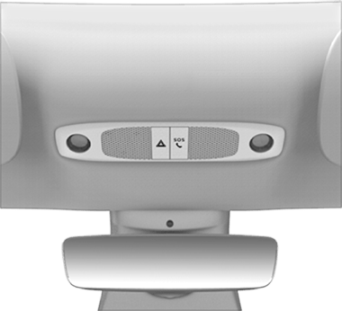
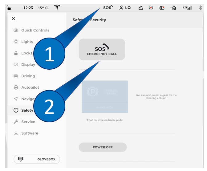
Front Overhead Console SOS eCall Places an eCall when pressed.
UI Button 1. eCall shortcut button which brings the user to the Safety & Security tab.
2. eCall button that places an eCall when pressed.
-
The UI shows the message below and counts down 12 seconds before it initiates an emergency call. As the countdown occurs, there is a voice prompt stating "An emergency call has been triggered, to cancel it use the display screen."
-
The emergency call can be cancelled by the user during the delay period by using the "Cancel Call" button on the UI.
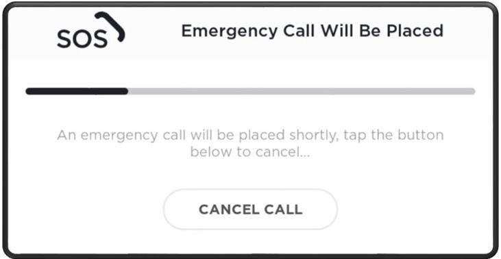
User Interface showing countdown to Emergency Call and "Cancel Call" CLICK HERE TO PLAY SOUND 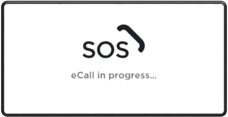
User Interface showing Emergency Call is in Progress -
When the countdown has ended, the emergency call is initiated.
- The emergency call can now only be cancelled by the PSAP operator.
- The MSD is sent to the PSAP operator.
- In case MSD transmission fails, it is will be re-transmitted.
- Voice call is set up between the vehicle occupants and the PSAP operator.
Automatic eCall Activationlink
In the case of automatic activation:
- The eCall system is notified of a emergency via the Emergency Notification Signal (ENS).
- The emergency call sequence is initiated without delay.
- The emergency call can only be cancelled by the PSAP operator.
- The MSD is sent to the PSAP operator.
- In case MSD transmission fails, it is re-transmitted.
- Voice call is set up between the vehicle occupants and the PSAP operator.
An ENS trigger is generated by the Restraints Control Module (RCM) in the following circumstances:
- When any airbag is deployed due to a detected impact.
- When any seat-belt pretensioner is deployed due to a detected impact.
- When High Voltage is disconnected due to a detected impact.
The eCalllink
Once the eCall has initiated, the MSD will be sent over,. If the transmission fails, the MSD will perform re-transmission. Following the transmission, a voice call is established so occupants and PSAP can communicate. The eCall can only be canceled by the PSAP.
If needed, the PSAP is able to return the call in case of lost connection or manual a hang-up on their end. The PSAP will dial back the vehicle with the phone number that is attached to the SIM profile used (Embedded/Removable 2FF SIM).
An eCall is designed to be difficult to stop and are long running (up to a 1 hour callback, also known as T9). eCalls are supposed to persist modem resets/reboots. In order to clear an eCall after one has been initiated, the services on the modem have to be stopped. During this time, other cellular service's are deprioritized for eCall.
If voice communication is not established (unconscious occupants), the PSAP will rely on the MSD transmitted.
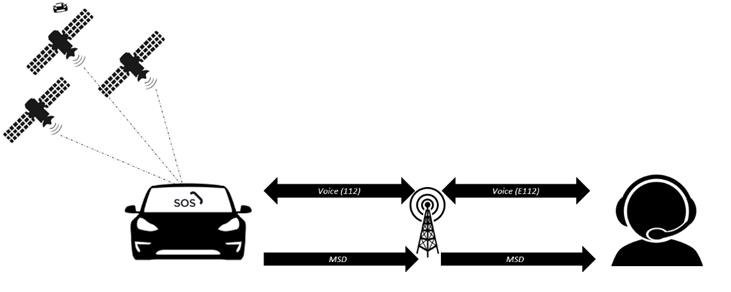 |
|---|
| Path of communication between vehicle and PSAP |
Functional Limitationslink
The eCall system cannot guarantee connection to the emergency services in areas where there is no cellular reception.
Privacy Concernslink
- There is no transmission of vehicle data during normal vehicle operation.
- There is no voice channel established with the answering point after vehicle data had been successfully transmitted.
- The eCall system is not permanently tracking the GPS location of the vehicle.
- Only when triggered will the vehicle location be sent to the emergency services included in the MSD.
- Vehicle speed is not explicitly sent in the MSD and cannot be implied from the data in the MSD.
- The system does not store records of successfully transmitted MSD.
- No voice logs are generated either during normal vehicle operation or during an emergency call.
Localizationlink
Localization GPS data for the eCall system comes from the GPS module in the Autopilot ECU.
The cell modem receives a new set of GPS coordinates every second, which are used to update the vehicle's last know location.
The latest coordinates are used when needed in the MSD packet.
Contents of the Minimum Set of Data (MSD)link
| Data value key | Supported data types | Description |
|---|---|---|
| msdVersion | INTEGER | MSD format version Format described in EN15722: 2015 |
| messageIdentifier | INTEGER | Message identifier, starting with 1 for each new eCall transaction Message identifier to be incremented with every application layer MSD re-transmission following a new 'Send MSD' request after the incident event |
| automaticActivation | BOOLEAN | True = Automatic False = Manual activation |
| testCall | BOOLEAN | True = Test call False = Emergency |
| positionCanBeTrusted | BOOLEAN | True = Position can be trusted False = Low confidence in position "Low confidence in position" shall mean that there is less than 95% confidence that exact position is within a radius of +-150 m of reported position |
| vehicleType | ENUM | The supported vehicle types are as follows: - passenger vehicle (Class M1) - buses and coaches (Class M2) -buses and coaches (Class M3) - light commercial vehicles (Class N1) - heavy duty vehicles (Class N2) - heavy duty vehicles (Class N3) - motorcycles (Class L1e) - motorcycles (Class L2e) - motorcycles (Class L3e) - motorcycles (Class L4e) - motorcycles (Class L5e) - motorcycles (Class L6e) - motorcycles (Class L7e) Vehicle definitions class M, N according to directive 2007/46/EC; class L according directive 2002/24/EC. |
| gasolineTankPresent | BOOLEAN | True = present False = not present |
| dieselTankPresent | BOOLEAN | True = present False = not present |
| compressedNaturalGas | BOOLEAN | True = present False = not present |
| liquidPropaneGas | BOOLEAN | True = present False = not present |
| electricEnergyStorage | BOOLEAN | True = present - False = not present |
| hydrogenStorage | BOOLEAN | True = present False = not present |
| otherPropulsionStorage | BOOLEAN | True = present False = not present |
| timeStamp | INTEGER (seconds) |
Timestamp of the initial data message generation within the current eCall incident event. The timestamp is represented in seconds elapsed since midnight January 1st, 1970 UTC. |
| positionLatitude | INTEGER (milliarcsec) |
Position latitude (WGS84) |
| positionLongitude | INTEGER (milliarcsec) |
Position Longitude (WGS84) |
| vehicleDirection | INTEGER (2 degree) |
The vehicle's last known real direction of travel expressed in 2º degrees steps from magnetic north (0-358, clockwise) determined at the latest moment possible before message generation. |
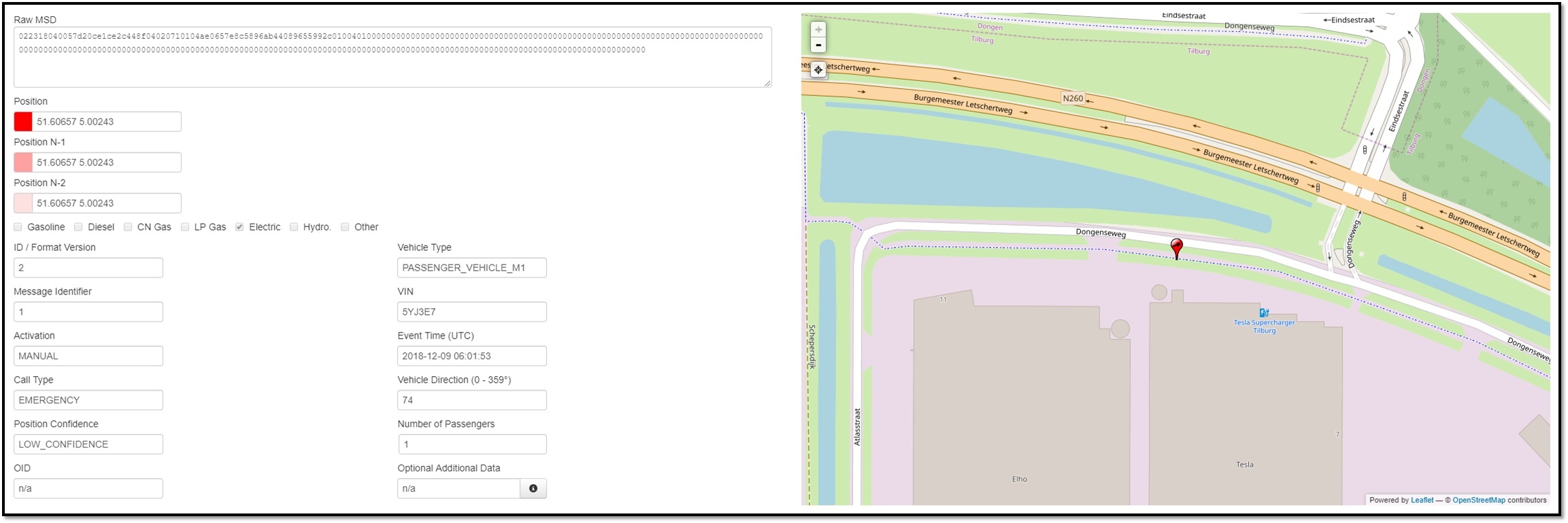 |
|---|
| eCall Developers Server showing MSD data transferred (VIN has been made anonymous) |
Hardware Componentslink
Front Overhead Consolelink
Mounted centrally in the vehicle above the rear view mirror is the Front Overhead Console (FOHC).
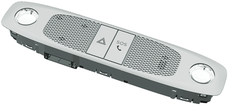 |
 |
|---|---|
| Front Overhead Console with SOS button | Front Overhead Console without SOS button |
The FOHC with an SOS button for eCall contains:
- Digital Microphone (LH)
- Analog Microphone (not longer being utilized)
- Manual SOS Button for eCall purpose
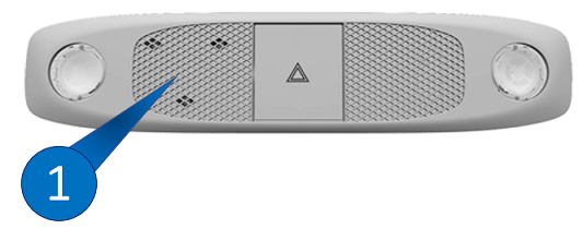
The FOHC without an SOS button contains only a Digital Microphone (LH).
Digital Microphonelink
The microphone module has 3 digital microphones and 1 A2B chip (slave) linked between the master controller and the Premium Audio module,making it an essential part of audio communication. The module sends digital audio data over Time-Division Multiplexing (TDM) to the car computer.
eCall voice is sent to the car computer to be processed towards the eCall modem. The digital microphone is located on the left side next to the hazard light button. the digital microphone is not part of the vehicle eCall Self-Test (see eCall Self-Test for more information), but is part of the Microphone eCall Test.
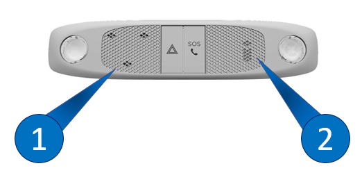 |
 |
|---|---|
| 1. Digital Microphones 2. Analog Microphone |
1. Digital Microphones |
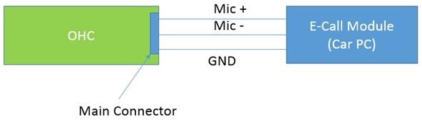
Analog Microphonelink
Note
The analog microphone is no longer used on vehicles with firmware version 2020.20 or later.
The analog microphone was only used for eCall voice recording. The analog microphone is located at the right side next to the manual SOS button.
During eCall Self-Test the analog microphone was tested for physical connection (see eCall Self-Test for more information).
 |
|---|
| Microphone blockdiagram |
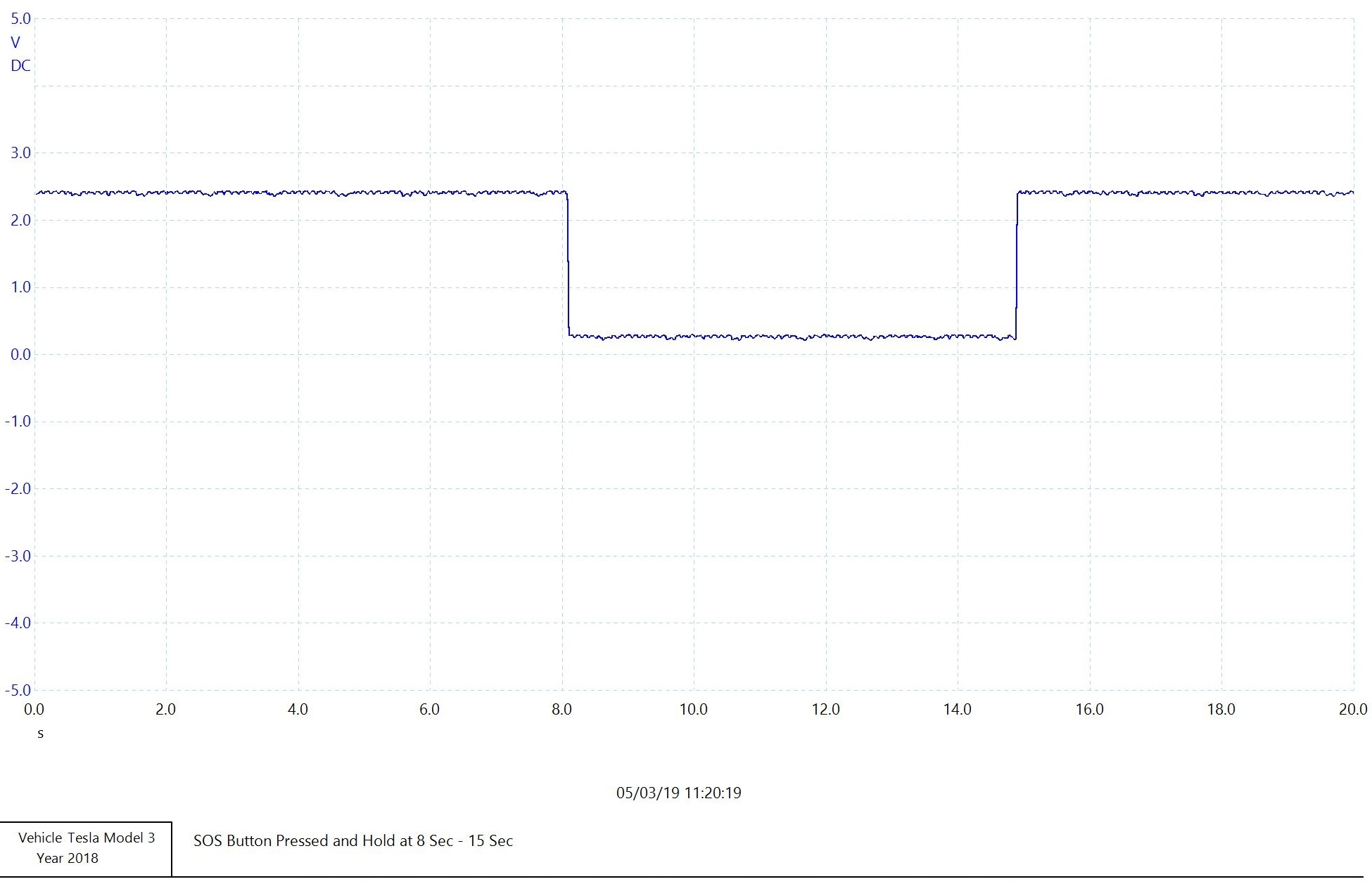
Manual SOS Buttonlink
The Manual SOS button that is either located on the touchscreen UI or next to the hazard lights button is an physical switch depending on vehicle configuration (for location, see image in Front Overhead Console section). The Manual SOS Button is directly connected to the car computer eCall logic connector.
 |
|---|
| Oscilloscope trace snip of a known good Manual SOS button |
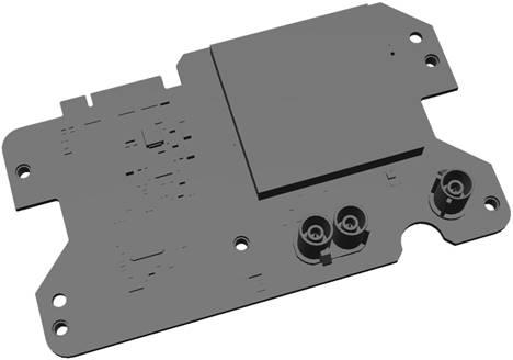
eCall Capable Cellular Modemlink
The vehicle's cell modem is used as the device that connects to the cellular networks and facilitates data and voice communication.
The modem is a replaceable daughter board integrated into the car computer unit. The European connectivity board is a screwed down variant fixed on the car computer infotainment board (this is not the case for North American connectivity boards).
When a modem is replaced with a new one, it is important to configure the modem as eCall capable. This can be done by running the ODIN routine Configure modem ECall. If this routine is not run, the modem will be stuck in reboot loop.
 |
|---|
| Connectivity board |
Backup eCall Cellular Antennalink
Vehicles built before October 2020 have a dedicated eCall cellular antenna, it is included to provide cell reception in case one or more of the eCall cellular antenna are damaged in the event of a collision.
When an eCall is triggered, the connection from the primary cell antenna in the right-hand side mirror is swapped to the dedicated eCall cellular antenna.
The connection to the secondary antenna in the left-hand side mirror is left in place (in case it is still intact). In the case of manual activation, the secondary antenna will be intact.
The dedicated eCall antenna is mounted internally within the dashboard and offers comparable performance to the primary cell antenna, roughly 500 m less reception range with GSM/3G capabilities.
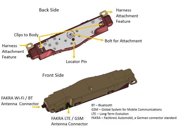
The eCall cellular antenna is connected directly with the use of a green keyed Fakra connector on both sides of the coax antenna to the eCall capable cellular modem.
 |
|---|
| Cellular Antenna on vehicles built before October 2020 |
The circuit relies on the 10 kΩ resistor located at the antenna. A DC phantom voltage (3,8V) is applied to the antenna connection to determine it is correctly connected.
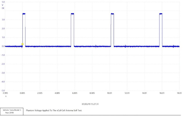 |
|---|
| Antenna phantom signal |
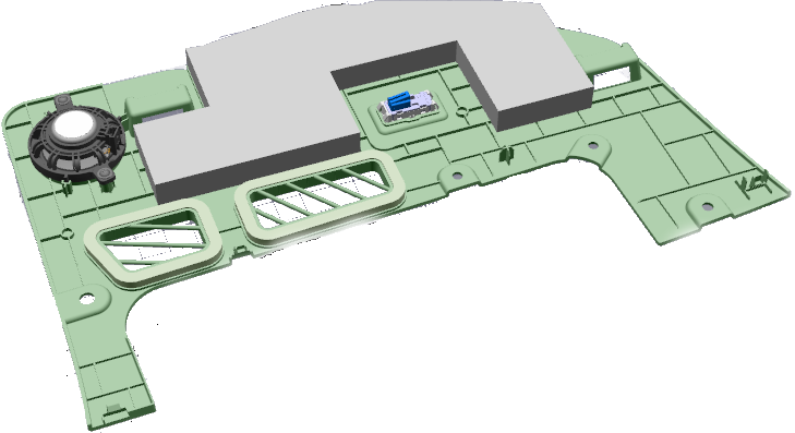
MIMO LTE/eCall Cellular Antennalink
Vehicles built after October 2020, will make use of the cellular antenna that is located in the left Multiple-Input, Multiple-Output (MIMO) behind the headliner at the B-pillar of right-hand or left-hand drive vehicles.
Note
Left and right side MIMOs are interchangeable.
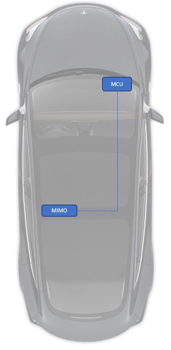 |
|---|
| MIMO Location |
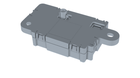
 |
|---|
| MIMO Component |
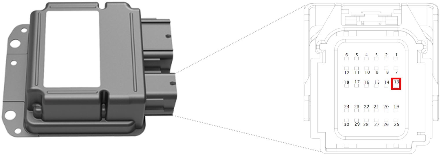
Restraint Control Module eCall Integrationlink
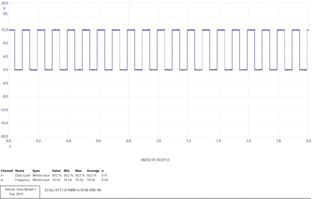
The Restraint Control Module (RCM) has a line running through the right vehicle controller (VCRIGHT) eCall passthrough to eCall for the distribution of the Emergency Notification Signal (ENS). During normal operation, the ENS is at 10Hz with a 50% duty cycle.
Restrains Hardware Type:
 |
|---|
| Restraint Control Module connector with highlighted ENS location (X200 pin13) |
 |
|---|
| ENS (RTA) signal provided from ENS to eCall at 10Hz, 50% Duty Cycle |
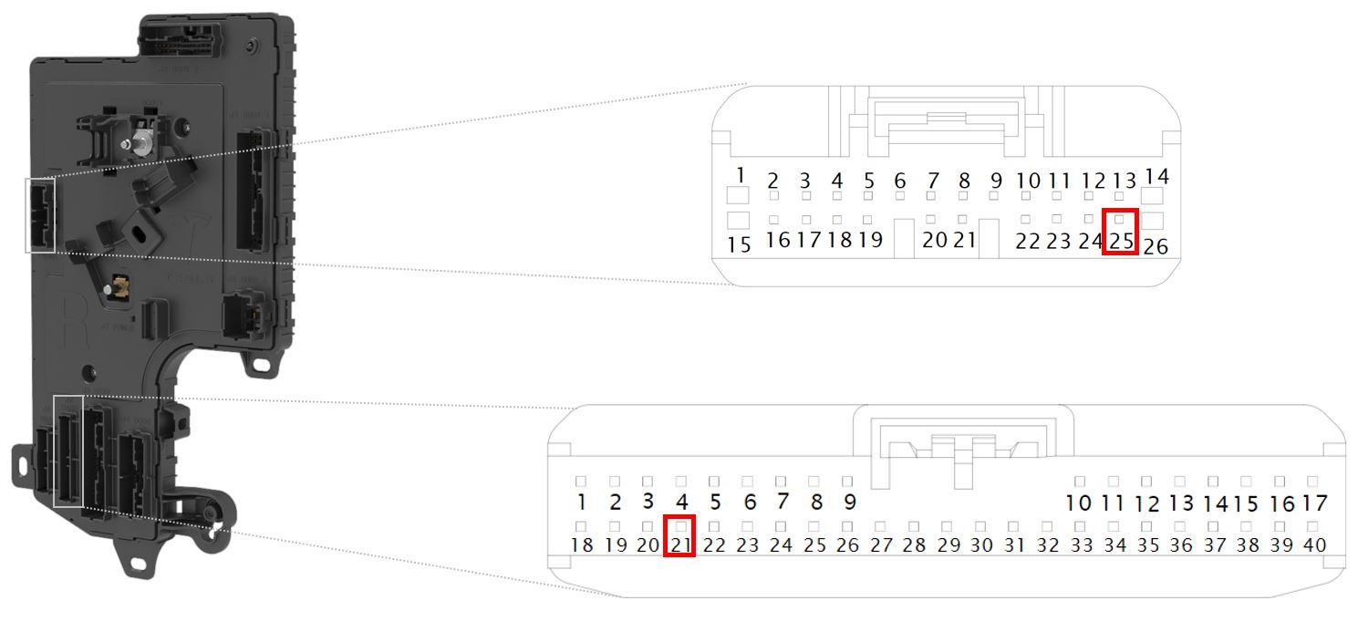
Right Vehicle Controller eCall Passthroughlink
The right vehicle controller (VCRIGHT) has a eCall Passthrough allowing the Emergency Notification Signal (ENS) to go through VCRIGHT to reduce wiring harness complexity.
 |
|---|
| X055 pin21 and X057 pin25 VCRIGHT eCall Passthrough |
eCall Emergency Speakerlink
The eCall system uses the same emergency speaker that the Autopilot ECU uses for its emergency audio output.
The position of the eCall emergency speaker is located at the front passenger foot well, dependent on whether the vehicle is right hand drive or left hand drive variant.
 |
|---|
| eCall Speaker |
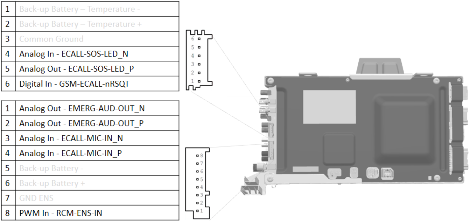
Car Computerlink
The car computer eCall related connections can be seen in the picture below:
 |
|---|
| Logic Connections Car Computer X173 / X174 |
GPS Antennalink
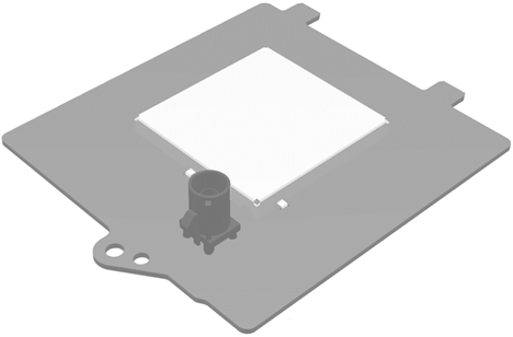 |
|---|
| GPS Antenna |
The Global Positioning System (GPS) antenna is located above the rear view mirror, next to the triple and interior cameras. It is powered by a coaxial cable that connects to the Autopilot ECU.
The GPS unit is able to use Global Navigation Satellite System (GNSS) signals from GPS, GLONASS, Galileo, or Beidou satellites. If there is limited reception (like in tunnels or underground parking), the GPS receiver is able to use dead reckoning. This feature uses the following to estimate the current position based on last known GPS position:
- Wheel speed and direction available on the CAN bus
- The GPS receiver internal accelerometer
- Gyroscope
The cell modem receives a new set of GPS coordinates every second, to update the vehicles last know location. The latest coordinates are used when needed in the MSD packet.
eCall Function Testslink
eCall Self Testlink
Once the drive rail is powered on, the eCall subsystem will run a series of self tests to ensure all critical components are connected (as seen in the table below).
| Test Item | eCall Client Logs Name | Test Criteria |
|---|---|---|
| ECall Backup Antenna: | cellAntennaConnected | eCall Backup Antenna needs to be connected (measurement of 10kΩ) |
| Cell Receiver Operability: | cellReceiverOk | |
| RCM ENS Signal: | rtaSignalOk | Airbag Module ENS Signal 10Hz with a Duty Cycle of 50% at non deployment |
| GPS Antenna: | externalGNSSOk, gnssAntennaConnected | GPS Antenna (needs to check) |
| Microphone: | micConnected, micOk | Analog Microphone Connected (Bias 150) |
| Valid Sim: | simPresent uimOperability |
Sim card present / Selected Ability to eCall |
| Emergency Speaker: | speakerConnected speakerOperability |
Emergency Speaker Connected (a "pop" can be heard during self test) |
| Modem Firmware: | modemFirmwareOk | Check if Modem Firmware is on the appropriate Firmware Version |
| Manual Button: | manualButtonOperability | Check if the Manual SOS Button is connected/ stuck/ shorted |
| Soft eCall button: | isDisplayAvailable | Check if the UI display is available |
| Backup Power Supply | backupBatteryOk | Test will be skipped as no backup power is used |
| Emergency Number: | Emergency Number in use (112) | |
| Call Counter: | Increment number of amount of eCall attempts | |
| statusIndicatorOk |
A failed self test will trigger a vehicle alert, shown to the end user:
 |
|---|
| eCall customer facing alert |
If a malfunction is detected the self test will perform multiple retries with a maximum of 3.
Note
During the self test, a "pop" from the emergency speaker is noticeable.
Toolbox ODIN eCall Self Testlink
An eCall self test can also be performed using Toolbox. This is the same self test that is initiated at the vehicle drive cycle startup.
Relevant eCall Alertslink
UI_a045_ECallNeedsService
The eCall Need Service alert is triggered depending of the outcome of the eCall self test.
UI_a055_ManualECallDisabled
Manual eCall Disabled is triggered by a self-test that analyzes the integrity of the manual SOS button input to the car computer.
If the alert triggers, it results in a user-facing message on the touchscreen UI. The ability to manually press the e-call SOS button is disabled for that ignition cycle.
Glossary of Terms for eCalllink
| Abbreviation | Description |
|---|---|
E112 |
A location enhanced version of the European wide emergency call number 112 |
ENS |
Emergency Notification Signal (from the RCM) |
EU |
European Union |
LHD |
Left hand drive (vehicle variant) |
GNSS |
Global Navigation Satellite System |
MIMO |
Multiple-Input, Multiple-Output (antenna unit) |
MNO |
Mobile Network Operator |
MSD |
Minimum Set of Data |
NTC |
Negative temperature coefficient |
FOHC |
Front Overhead Console |
PSAP |
Public-safety answering point |
RCM |
Restraints Control Module |
RTA |
Real Time Analyze |
RHD |
Right hand drive (vehicle variant) |
SOS |
Internationally recognized distress signal |