Safety and Restraintslink
Last updated: November 12, 2024
Overviewlink
2021+ Model X is equipped with a Tesla Supplementary Restraint System, which comprises of the following components:
- Restraint Control Module (RCM)
- Occupant Classification System (OCS)
- Occupancy sensor
- Passenger seat track position sensor
- Impact / pressure sensors
The TSRS is designed to work in conjunction with the seat belts. TSRS supplements, but does not replace, the protection afforded by seat belts. Seat belts are proven to be the single most effective safety device in a vehicle and should always be worn. Properly worn seat belts also ensure the occupant is seated in the optimal position to benefit from the full effectiveness of the airbags and seat belt pretensioners.
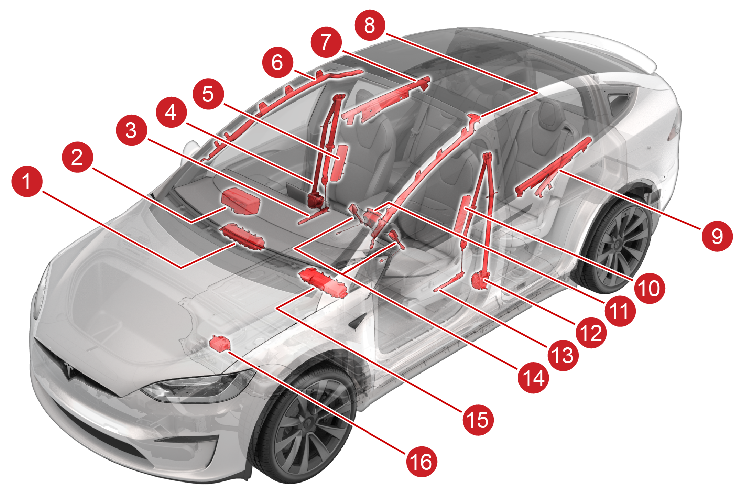
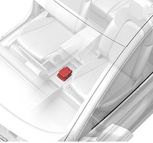
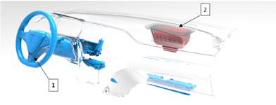
Location of Airbag and Seat Belt Componentslink
The following images shows the components of 2021+ Model X Safety Deployment System.
 |
|---|
| 1. Passenger knee airbag: North America only 2. Passenger airbag 3. Passenger lap pretensioner 4. Passenger seatbelt / retractor 5. Seat outboard side airbag - RH 6. Curtain airbag - RH 7. Rear airbag - RH 8. Curtain airbags - LH 9. Rear airbag - LH 10. Seat outboard side airbag - LH 11. Driver airbag 12. Driver seatbelt / retractor 13. Driver lap pretensioner 14. 1st row seatbelt buckles (x2) 15. Driver knee airbag: North America only 16. Pyrotechnic fuse |
| Safety Deployment System |
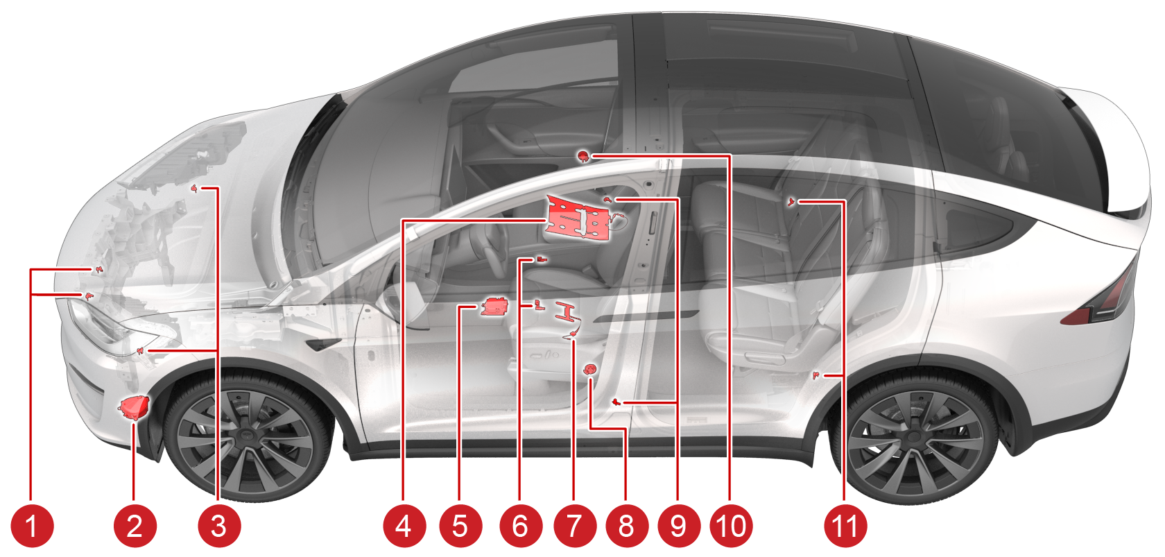
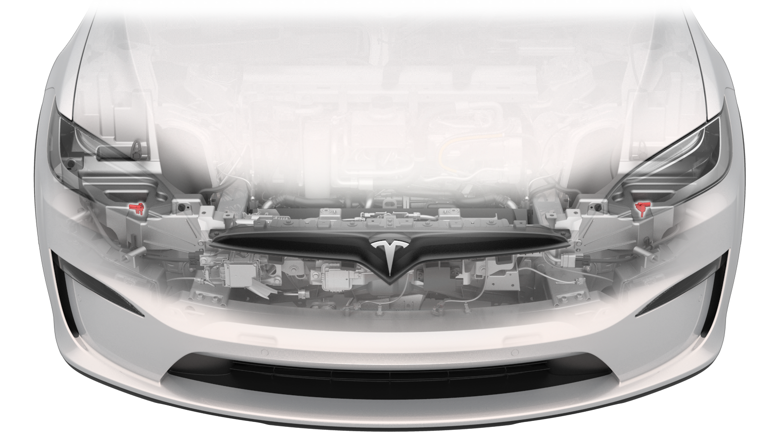
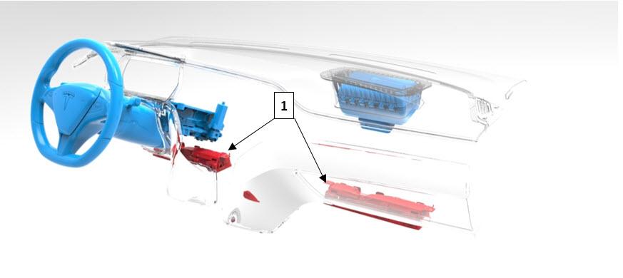
Location of Accelerometers and Pressure Sensorslink
The following images shows the safety and restraint sensors of 2021+ Model X .
 |
|---|
| 1. Accelerometer Bumper Mid Left/Right (Front Middle Left/Right Satellite Impact Sensor) 2. Pedestrian Warning Speaker (PWS) 3. Accelerometer Front Left/Right (Front Left/Right Satellite Impact Sensor) 4. Passenger Occupant Classification System mat (North America only) 5. Restraints Control Module (RCM) 6. Seat track position sensors (x2) 7. Driver Seat Belt Reminder (SBR) 8. Front door pressure sensor - LH 9. B-Pillar accelerometers (x2) 10. Front door pressure sensor - RH 11. C-Pillar accelerometers (x2) |
| Restraints Sensor and Electrical System |
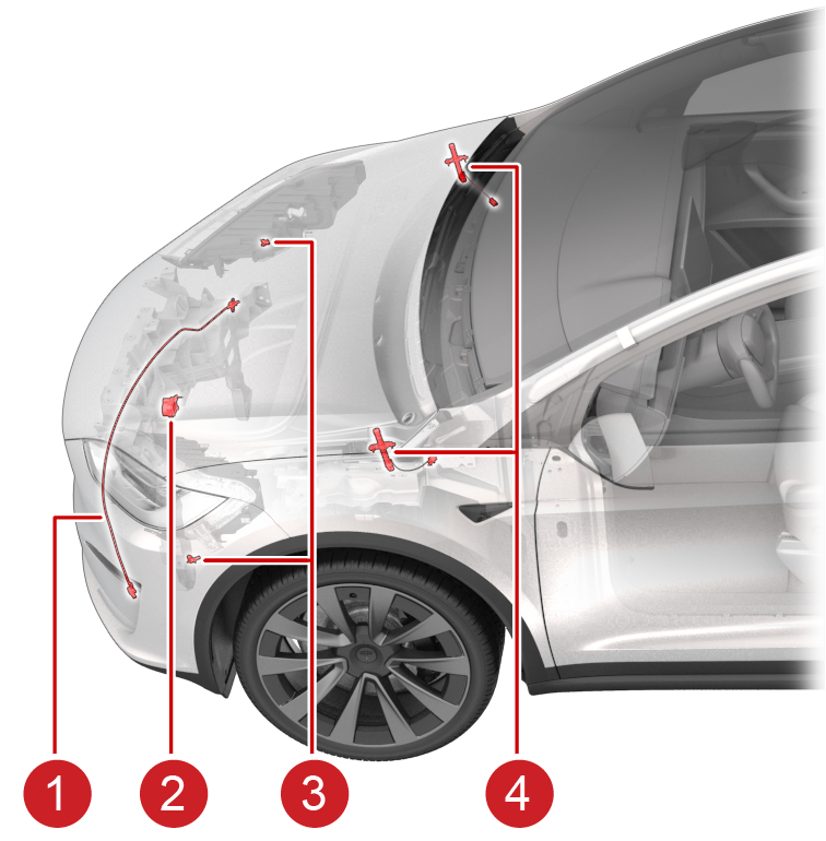 |
|---|
| Vehicles outside of North America include these additional components as well as those outlined in the previous image. 1. Ped-Pro pressure tube 2. Front End Module (FEM) siren 3. Headlamp bracket accelerometers (x2) 4. Hood actuators |
| Restraints Sensor and Electrical System - Rest of World additional sensor |
Theory of Operationlink
2021+ Model X has a large variety of airbags which, when combined with the seat belts, safely dissipate the occupant’s kinetic energy during an impact. The amount of kinetic energy the airbags must absorb depends on the change in the velocity of the vehicle and the size of the occupant.
Advanced dual stage airbags in the front row of a 2021+ Model X vehicle are able to tune this energy absorption for different speeds or passenger sizes. Seat sensors, such as the Occupant Classification System (OCS) (North America only), and seat track position indicates the passenger's size while the crash accelerometer and velocity measurements helps estimate the occupant speed. The information is continuously fed into the Restraint Control Module (RCM) where, in the event of a crash, the appropriate energy absorption needed from the seat belts and airbags can be determined.
Seat beltslink
Seat belts in the front row are equipped with a deployable load limiter, which adjusts the amount of energy the seat belts absorb from the occupant. The load limiter is integrated into the seat belt retractor assembly. To minimize the risk of occupant injury, the load limiter can be deployed to lessen the maximum tension in the seat belts. When load limiters are deployed, the energy absorbed by the seat belts is decreased, which allows the airbags to absorb occupant energy more effectively. The system is only deployed in frontal and side impacts where the airbags are most effective. In cases when there is an impact that has both forward and lateral motion or is a a rear impact, the seat belts absorb as much energy as possible.
Airbagslink
Airbags are most effective when the occupant is in a specific position as they are deployed. Seat belt pretensioners are used to help prepare the seat belt to absorb occupant energy and move the occupant to the best position before they impact the airbag. Front row occupants in the driver and passenger seats have the shoulder retractor pretensioner located within the retractor under the B-Pillar trim while the lap belt pretensioner is located in the seat. Second row outboard passengers are positioned by the shoulder belt from a pyrotechnic retractor in the back of each seat. The middle seat (if equipped) does not have a pretensioner. Retractor pretensioners pull on the shoulder belt, while lap (or anchor) pretensioners pull on the lap belt.
The first row and second row outboard occupants are protected in crashes with a lateral motion (side, angled, or offset type crashes) by side curtain and seat airbags. The front row curtain airbags deploy down from the upper A-pillar trim area. The outboard second row occupants are protected by head airbags that deploy from the upper section of the lower rear door trim. Seat airbags inflate from the outboard seat bolsters to soften occupant hip and leg contact with the door trims.
In North American markets, the front row occupant’s legs are also protected from trim contact in a frontal impact by knee airbags, which deploy in frontal crashes. However, the knee airbag will not deploy when a belted occupant is seated in the passenger seat and the seat is in front of a pre-determined point in the seat track travel (closer to the airbag module). The RCM dictates the stage 2 threshold based on signal severity. The Seat Track Position Sensor (STPS) will determine the knee airbag deployment strategy for belted occupants.
Collisionlink
In the event of a collision with the drive rail on, the pyrotechnic fuse is deployed to isolate high voltage to the high voltage (HV) battery. All crash modes (including front, side, or rear) that exceed the programmed threshold will trigger the pyrofuse. The fuse disables high voltage by breaking continuity.
Serviceabilitylink
All deployable safety systems, such as airbags, seat belt pretensioners, and the pyrofuse, are single-use pyrotechnic devices and must be replaced after any type of deployment. All partially deployed devices (except the load limiters) will completely dispose of their pyrotechnic component within a short period of time of impact detection. Seat airbag deployment will require a full seat replacement in the event of a crash with lateral motion. While deployed, safety devices are designed to be inert after a crash to protect occupants and first responders. Any pyrotechnic device should be handled with all proper procedures and care according to the vehicle Service Manual.
Note
For more information, refer to Collision Repair Procedure SRS Inspection and Component Replacement.
Airbag Deployment Situations - Drive Rail Onlink
Although the airbags and pretensioners are designed to be triggered electrically, they are pyrotechnic devices and could deploy unexpectedly — even when not connected to an electrical source — if proper transport, storage, and handling methods are not followed. Always follow Service Manual procedures when diagnosing or repairing the Tesla Restraint System. Only use Tesla-approved equipment to intentionally deploy a pyrotechnic device for disposal purposes.
Warning
Accidental deployment can cause damage and personal injury. Always refer to the Owner's Manual for correct use of the Tesla Restraint System and seat belt systems, and to the Service Manual for correct fitment, repair, and disposal of system components.
Component Specificationslink
Restraint Control Module (RCM)link
 |
|---|
| Restraint Control Module (RCM) |
 |
|---|
| Restraint Control Module (RCM) location |
The TSRS is controlled by the RCM, which includes fault detection and warning circuits. If a fault is detected, an indicator light in the instrument panel notifies the driver. Alerts (with the Electronic Control Unit (ECU) prefix "RCM2") are also retrievable using the vehicle controller area network (CAN) logs, vitals, or Periscope.
The RCM is calibrated specifically to the vehicle model. It contains accelerometers to measure forces acting on the vehicle and circuits for monitoring the condition of all pyrotechnic devices. It is the primary device that commands the deployment of all TSRS components. During a deployment, the system will run current through individual components to trigger the pyrotechnics. Each stage and part has its own independent wire loop for this triggering signal.
The RCM monitors the restraint system electrical components and circuitry when the drive rail is on. The RCM uses an internal six axis inertial measurement unit (IMU) to monitor all 3 angular velocities, as well as 3D accelerations of the vehicle. The module is located under the center display.
The acceleration and angular rate data from the RCM is broadcasted on the Chassis CAN and Party CAN to other vehicle systems for use in traction control, stability control, and other dynamic control algorithms. If the internal sensor detects a high acceleration event, it looks at the data from the satellite sensors to determine the type and severity of the crash. The RCM will only deploy safety components if both of these sensor signals are available and agree. When the signals exceed the threshold limits, the RCM directs current through the appropriate deployment loops to deploy the airbags, pretensioners, and commands the HV disconnect as necessary.
In case of a deployment collision, the RCM stores certain information about the event. The module is able to store data for a maximum of two independent events. Non-deployment events can be overwritten by subsequent events, but deployment events cannot be overwritten. If both data records have been stored as full deployments, the module will not allow any additional events to be stored. The RCM needs to be replaced after any deployment event since the data cannot be overwritten. The data is only available when pulled using the proprietary Tesla Event Device Reader (EDR) tool or it can be obtained via instructions on edr.tesla.com. The EDR system is entirely separate from the data storage on the gateway after a crash is detected. EDR is currently only supported for vehicles manufactured for the North American market or China.
When deployment occurs, the RCM sends a collision detection CAN message to the body controller, which then does the following actions:
- Switches on hazard lights
- Unlocks all doors
- Unlocks the trunk
- Opens the glove box for access to registration papers
- Vents windows
- Places an eCall (only in Europe)
The gateway will:
- Initiate a standard log pull
- Pull and package the RCM information
- Attempt to gather any Automated Emergency Braking or Side Collision Avoidance data from the Driver Assistance System (DAS)
The vehicle will also attempt to package these items and immediately upload them to the vehicle CAN logs. If this process fails, there is currently no retry mechanism, and the data will have to be pulled manually from Toolbox.
The RCM performs diagnostic monitoring of the Tesla Restraint System electrical components and deployment loops for malfunctions while the drive rail is on. The module requests the instrument cluster to display the airbag indicator light if a malfunction (bad deployment circuit or missing sensor) is detected. The RCM stores a Diagnostic Trouble Code (DTC) and sends a CAN message that is stored in the vehicle logs.
Sensor Detailslink
2021+ Model X uses a combination of accelerometer sensors (impact sensors) and pressure sensors to sense the impact. Installed hardware varies per Region.
| Sensor | North America | Rest of World |
|---|---|---|
| Accelerometer Front Left (Front Left Satellite Impact Sensor) | 1 | 1 |
| Accelerometer Bumper Mid-Left (Front Middle Left Satellite Impact Sensor) | 1 | 1 |
| Accelerometer Bumper Mid-Right (Front Middle Right Satellite Impact Sensor) | 1 | 1 |
| Accelerometer Front Right (Front Right Satellite Impact Sensor) | 1 | 1 |
| Accelerometer B-pillar Left | 1 | 1 |
| Accelerometer B-Pillar Right | 1 | 1 |
| Accelerometer C-Pillar Left | 1 | 1 |
| Accelerometer C-Pillar Right | 1 | 1 |
| Pressure Sensor FL Door | 1 | 1 |
| Pressure Sensor FR Door | 1 | 1 |
| PedPro - Pressure Sensor LH Bumper Foam (Pressure Tube) | - | 1 |
| PedPro - Pressure Sensor RH Bumper Foam (Pressure Tube) | - | 1 |
The RCM uses the data from these sensors to determine if a collision is severe enough to warrant any airbag and / or seat belt pretensioner deployment. Data from the front left hand (LH) and right hand (RH) accelerometers are compared to determine if the impact contains offset or is angular.
 |
|---|
| Angled and offset impact |
Both the accelerometers and the pressure sensors communicate with the RCM with a so-called PSI5 communication protocol. This allows multiple sensors to be connected to the same line (a bit like multiple CAN nodes that communicate on a single CAN network) and it allows the RCM to detect hardware failures such as open loop, short and it can detect if a wrong sensor is installed.
Accelerometerslink
2021+ Model X is equipped with eight (North America) or ten (Rest of World) accelerometers. Accelerometers, also called impact sensors, contain a device that monitors the attached component's relative acceleration to the RCM.
 |
|---|
| Accelerometer Sensors |
Two front bumper (mid-left / mid-right) Accelerometers, also called satellite sensors.
|  |
| --- |
| Front Bumper Satellite Sensor Location |
|
| --- |
| Front Bumper Satellite Sensor Location |
Two headlamp bracket accelerometers help detect frontal offset impacts.
 |
|---|
| Headlamp Bracket Sensor Location |
Two B-Pillar accelerometers help detect side impacts. The B-Pillar sensor is located on the lower portion of the B-Pillar.
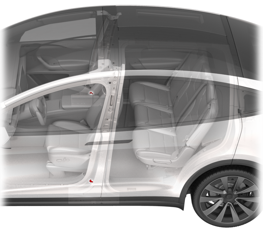 |
|---|
| B-Pillar Accelerometer Sensor Location |
Two C-Pillar accelerometers help detect side impacts. The C-Pillar sensor is located on the lower portion of the C-PIllar closest to the door frame.
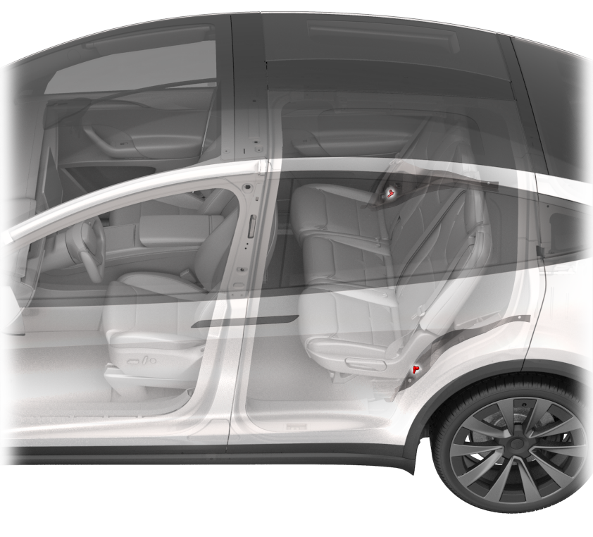 |
|---|
| C-Pillar Accelerometer Sensor Location |
Pressure Sensorslink
2021+ Model X is equipped with two (North America) or four (Rest of World) pressure sensors. Pressure sensors are piezo-electric pressure sensors mounted inside the front LH and RH doors measure the dynamic pressure change caused by deformation of the door in a side crash. They require a sealed door compartment to work properly. The inputs from the pressure sensors are processed by the RCM to deploy the side airbags and the seat belt pretensioners.
Warning
Always reinstall or replace any plugs or tape removed from the door shells when servicing components inside the door. The pressure sensors are precisely calibrated to respond to pressure changes within the door in the event of a collision. Opening more holes in the door creates more escape paths for air, which diminishes the sensor's ability to accurately detect a side impact and can negatively affect airbag deployment.
 |
|---|
| Pressure Sensors |
Two pressure sensors in the front doors.
 |
|---|
| Door Pressure Sensor Location |
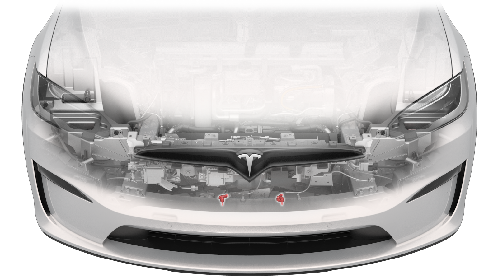
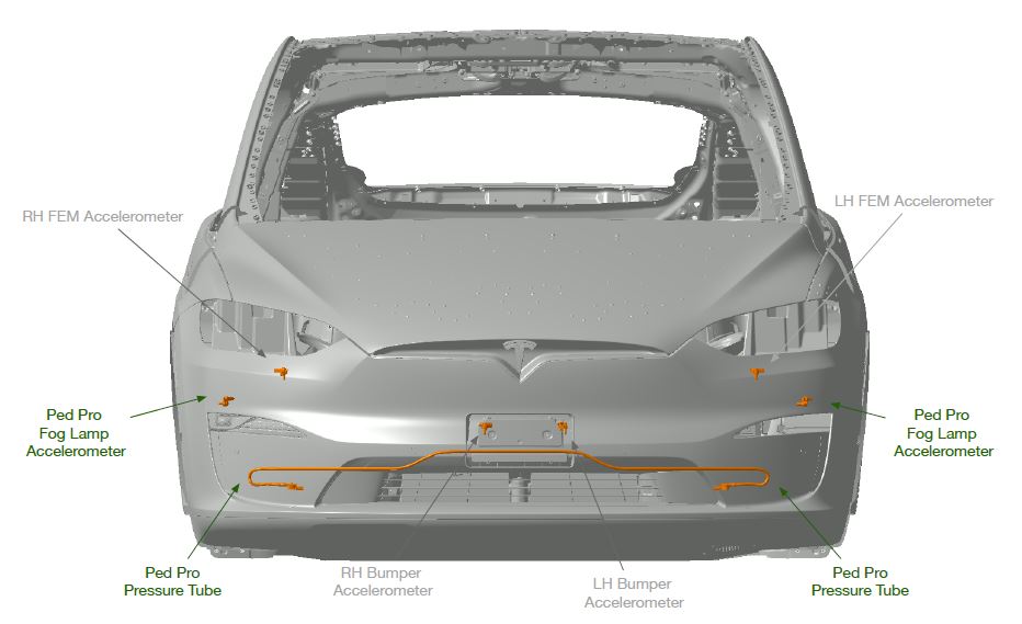
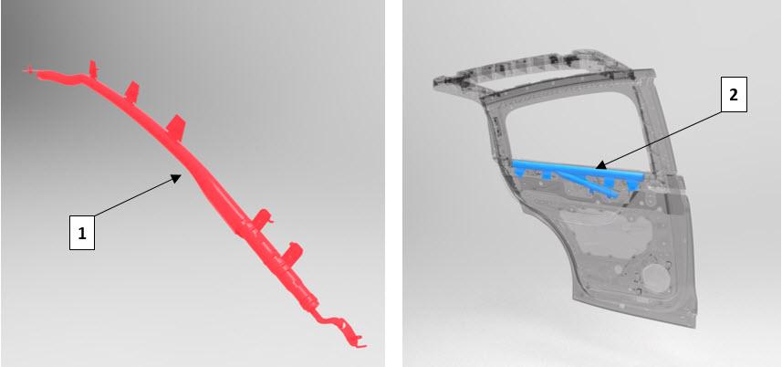
Additional Pedestrian Protection Sensors (Europe and Asia only)link
2021+ Model X vehicles built outside of North America include the Pedestrian Protection system. This system includes two additional pressure sensors located at either end of a pressure tube located in the front fascia, and two actuators at the hood hinges. The pressure sensors, along with the accelerometers, sense the change in pressure and acceleration, and then deploys the actuators in the hood to create empty space under the hood. This decreases the severity of injury and protects the pedestrian from becoming more injured in the event of a frontal collision.
Two PedPro front fascia accelerometers sensors and two pressure sensors, one on either end of the pressure tube.
 |
|---|
| PedPro - Pressure Tube |
Seat Belt Buckle Switchlink
 |
|---|
Five seat belt buckle switches are fitted to determine the deployment strategy for lap and shoulder pretensioners, and load limiters. The front row seats each contain a shoulder pretensioner, lap pretensioner, and a load limiter, while the 2nd row outboard seats only contain shoulder pretensioners. The middle seat is not fitted with a pretensioner. For the front passenger seat, the seat belt buckle switch also determines the active vent deployment strategy for larger occupants.
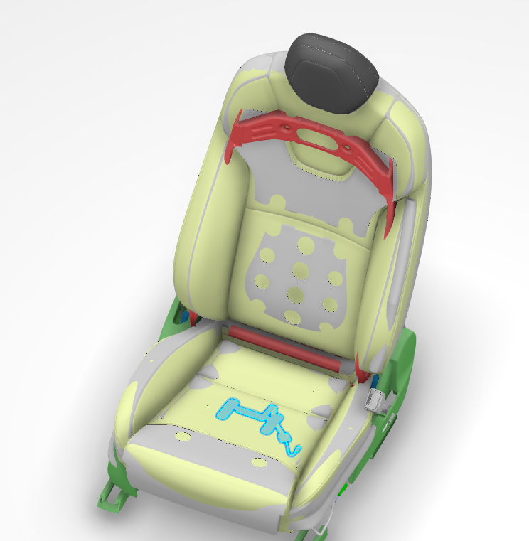
Occupancy Sensorslink
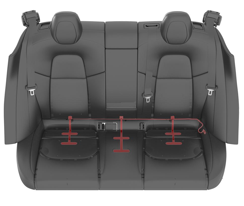
All seats contain occupancy sensors or resistive pads, with the exception of the front passenger seat, which contains a sensor that performs the same task as the occupancy sensors and has additional functionality. The occupancy sensors are located in the seat cushions. The occupancy sensors are switches distributed throughout the cushion connected both parallel and in series. Having the sensors distributed throughout the cushion helps to prevent situations where small items might trigger the seat belt reminder indicator.
 |
|---|
| Seat Belt Reminder (SBR) Sensor |
 |
|---|
| Driver Occupancy Sensor |
The occupancy sensors are also referred to as the Seat Belt Reminder (SBR). The SBRs sensors are fitted in the seat cushion and are located in the driver, 2nd row passenger, and 3rd row passenger (if configured) seats. In North America, the SBR is not in the front passenger seat because it has an OCS sensor, which has SBR capabilities. The gateway uses the driver SBR input for vehicle on/off, gear selection, and parking brake behavior.
The SBRs always actuate for 5th percentile occupants and larger, but they may actuate for other smaller occupants or objects below this weight. The second row outboard seat controllers (BCS2R and BCS2L) handle signals from the 2nd and 3rd row SBR and seat belt buckle switches on their respective sides, and then broadcasts the statuses over the Body CAN. The middle second row seat controller (BCS2C) only handles signals from its SBR and seat belt buckle. The SBR, in conjunction with the seat belt buckle switch, indicate whether an occupant is seated in the seat with the seat belt buckled. Depending on the vehicle region, there are various audible and visual chimes indicating to the customer that an occupied seat does not have the seat belt buckled. The performance and behavior of these audible and visual chimes differ from region to region. The user interface (UI) will display any visual indication of a unbuckled seat.
When occupied, the resistance should read 1 kOhm. When unoccupied, the resistance should read 11 kOhm.
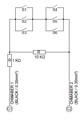 |
|---|
| Driver Occupancy Sensor - Circuit |
 |
|---|
| Rear Passenger Occupancy Sensors |
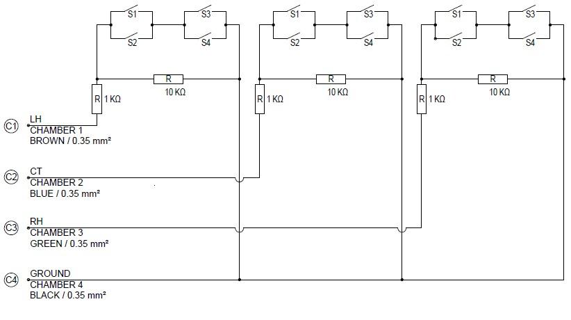 |
|---|
| Rear Passenger Occupancy Sensors - Circuit |
The 1st row driver and passenger seat belt telltales are combined together into a single indicator. The symbol shown below can be seen on the center display and is visible at all times. All seat belt telltales are displayed as an overhead view of all seats.
Occupant Classification System (North America only)link
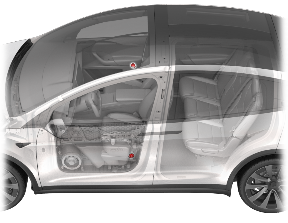
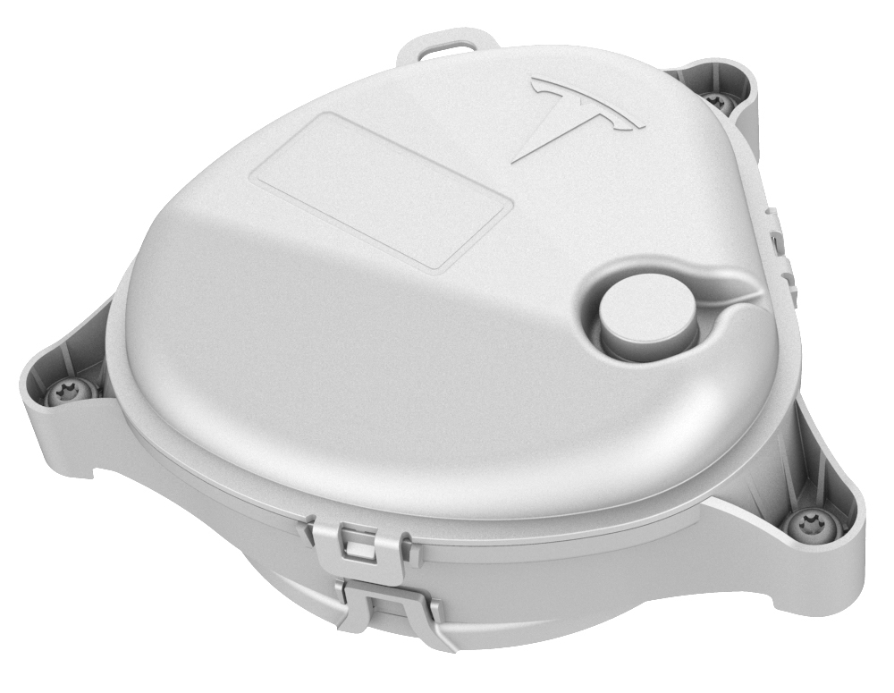
Occupant Classification System is a system that detects who's sitting in the passenger seat. OCS is made up of 2 individual components: the OCS Electronic Control Unit (ECU) and the OCS sensor mat. The OCS monitors the conductive presence on the seat cushion to detect if an occupant is sitting in the front passenger seat. The OCS communicates via a Local Interconnect Network (LIN) to the right vehicle controller (VCRIGHT).
VCRIGHT then communicates the status to the RCM (RCM2) using a CAN signal. The RCM uses this information to determine whether to enable or suppress the deployment of the front passenger airbag and, if applicable, the corresponding knee airbag. The OCS ECU sends a classification to the RCM where the passenger airbag light state is determined by the RCM's receipt of the OCS classification. The RCM transmits a signal to the Microcontroller Unit (MCU) requesting the passenger airbag state light (PASS AIRBAG OFF).
 |
|---|
| Occupant Classification System (OCS) sensor mat |
 |
|---|
| Occupant Classification System (OCS) Electronic Control Unit (ECU) |
Note
Seat position, occupant size, and weight distribution affect the sensed values. An occupant whose weight is near the classification thresholds can cause the airbag deployment strategy to toggle between regions.
The OCS measures the capacitance on the seat cushion to determine the occupant contact area in the front passenger seat. The ECU compares this capacitance change to the internally stored threshold to determine whether the seat is occupied or not. The OCS sends this information to the RCM to disable the front passenger airbag and the knee airbag.
| Front Passenger Seat Occupancy | Passenger Airbag Indicator Touchscreen - North America | Passenger Airbag Stages |
|---|---|---|
| Seat empty, child seat, or small child | PASS AIRBAG OFF | None |
| Occupied (>100 lbs) | PASS AIRBAG ON | 1st and 2nd |
Occupancy Stages
The RCM notifies the occupants of the disabled status by displaying the PASSENGER AIRBAG OFF indicator on the MCU. If a fault is detected, the OCS sends a message to the RCM. The RCM responds by sending a command message to the MCU and then triggers the warning lamp on the UI. The calibration for this system is completed by a Toolbox routine when it is new. For 2021+ Model X vehicles sold outside of North America (Rest of World), instead of using the OCS, there is a passenger airbag cutoff switch, which allows the customer to toggle the airbag on or off.
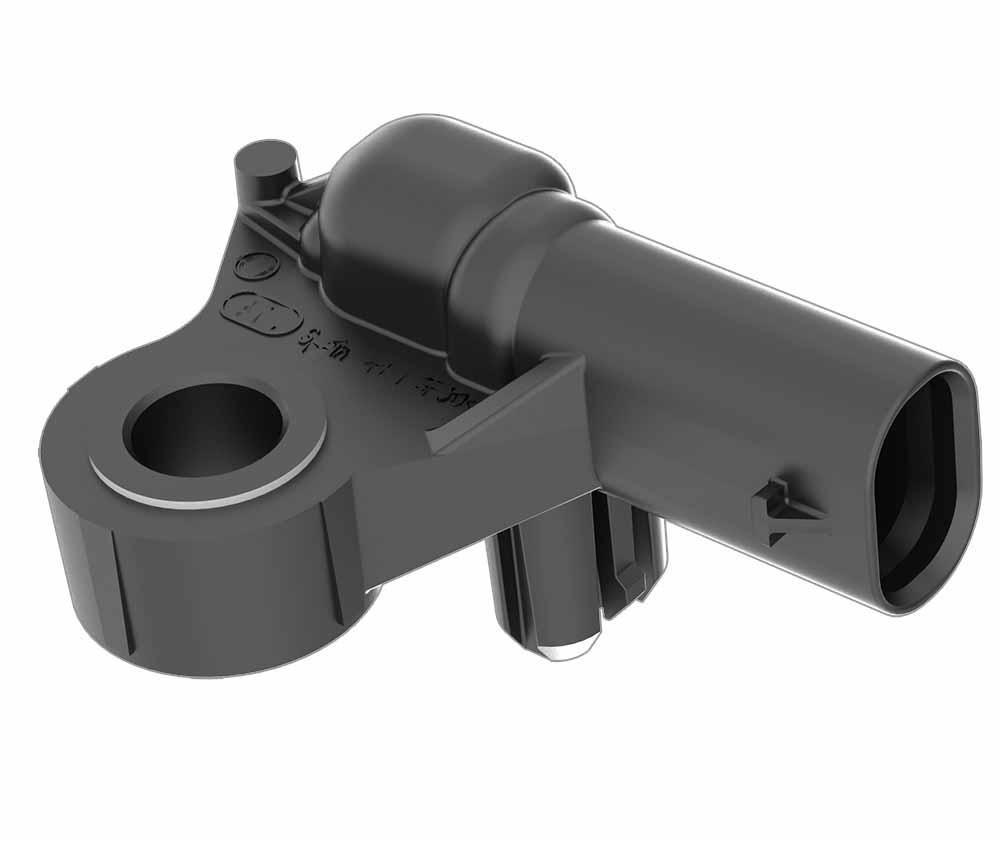
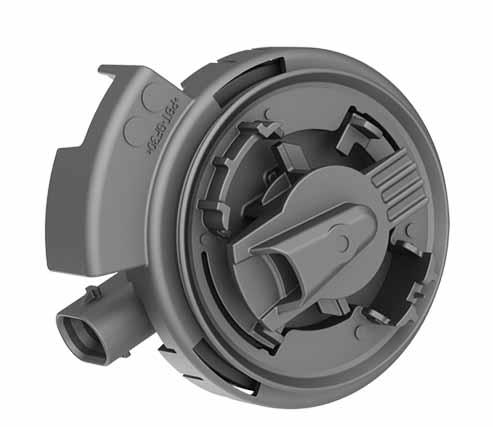
Passenger Seat Track Position Sensor (North America only)link
 |
|---|
| Seat Track Position Sensor (STPS) |
The Seat Track Position Sensor (STPS) is used to determine the distance between the passenger seat and the front airbag. The information from the STPS is used by the RCM to modify active vent and seat belt load limiter deployment times, as well as suppress the knee airbag (when seat belt is buckled) if the seat is in front of a pre-determined point in the seat track travel (closer to the airbag module). The STPS is a hall-effect sensor mounted on the outboard seat track of the passenger seat. The seat track includes a metal bracket that shunts the STPS magnetic circuit, creating two states of seat position. The shunted state represents a rearward seat position, and the non-shunted state represents a forward position where metal is not present next to the sensor. These two states are inputs to the RCM.
The STPS is connected to the seat vehicle controller (VCSEAT), which sends its status to the VCRIGHT. The VCRIGHT then forwards the information to the RCM.
The sensor is attached to the seat track with one screw.
 |
|---|
| Seat Track Position Sensor (STPS) (North American vehicles only) |
Deployable Restraintslink
Warning
Airbags inflate with great force in a fraction of a second. A vehicle occupant could be seriously injured or even killed if sitting closer than 10in (255mm) to the airbag or if they are seated incorrectly. Do not place any objects in the path of airbag deployment, such as on top of the passenger side instrument panel.
Airbags consist of a housing, an inflatable airbag, initiating devices, and a canister containing a gas generating material.
The driver and passenger upper body airbags have 2 stages of main bag deployment. For low energy frontal collisions, the airbags deploy at less than full deployment, which is Stage 1 of the airbag. For more severe frontal collisions, a full airbag deployment (both Stage 1 and Stage 2) is initiated. The current passing through the airbags ignites the material in the canister, producing a rapid generation of gas. The gas produced from this reaction rapidly inflates the airbag. Once the airbag is inflated, it quickly deflates through the airbag vent holes and/or the airbag fabric.
The passenger front airbag is equipped with a third deployment device called an active vent. An active vent can be deployed to allow the airbag to deflate more quickly, reducing the total energy absorption of the bag. Quicker airbag deflation is useful when trying to steadily absorb the lower energy of a smaller occupant. Active vent deployment will thus depend on information from the OCS in the front passenger seat.
Upon detection of a circuit malfunction, the RCM sets a DTC and informs the driver by displaying the Tesla Restraint System airbag indicator in the instrument cluster.
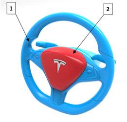
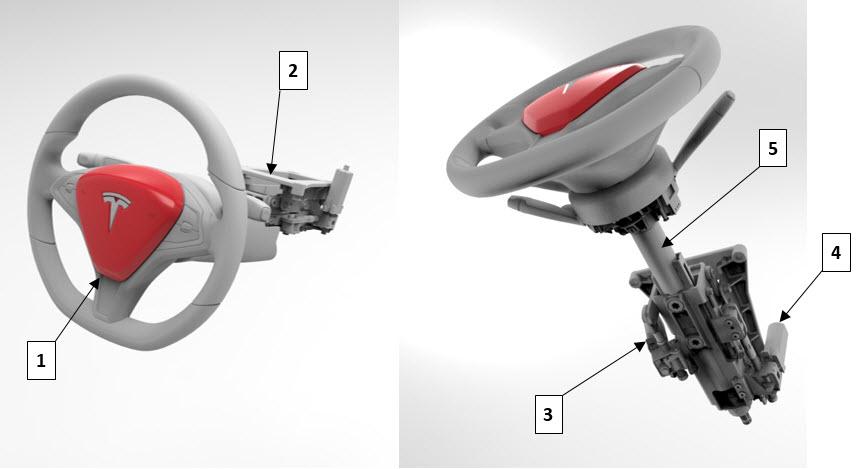
Driver Front Airbaglink
 |
|---|
| 1. Steering wheel 2. Driver front airbag |
| Driver Front Airbag |
The drivers airbag deploys from the yoke or steering wheel, it is a two stage circular airbag with active vent. In North American vehicles the first stage is for less severe frontal impacts. The second stage shall only deploy in more severe cases to get the bag into position faster and provide increased stiffness. The active vent helps to lower the stiffness of the bag later in the event, the vent is used in cases where perpendicular contact with the bag is made (no offset or angle in the impact). 'Rest of World' vehicles are fitted with a single stage in ator without an active vent, optimized for belted load cases.
Knee Airbags (North America only)link
 |
|---|
| 1. Knee airbags |
| Knee Airbags |
Knee airbags for the driver and front passenger are located on the lower part of their respective dashboards and are designed to deploy against the occupant’s lower legs, reducing the forward momentum of the lower body during a mid- to high-speed frontal impact. Driver side deployment is dependent on the logic determined by the RCM, and the passenger side deployment is dependent on the logic determined by the OCS and the RCM. When deployed, the knee airbag pushes against the occupant's lower legs, contacting them at the knee cap level and cushioning the legs down to the shin and ankle level to hold the occupant in a proper position in the seat.
Passenger Front Airbaglink
 |
|---|
| Passenger Front Airbag |
he passenger airbag deploys from the top of the instrument panel, it is a two stage airbag (with active vent in North American markets). The airbag contains `bull horns' to help control the lateral and rotational motion of the head, particularly in frontal impacts with a lateral component. The second stage will deploy in more severe cases to get the bag into position faster and provide increased stiffness. The active vent helps to lower the stiffness of the bag later in the event, the passenger active vent is used for forward seating positions or with a long delay for large unbelted occupants when no angle or offset is detected. Airbags not fitted with active vent have larger discrete vents.
Curtain Airbagslink
 |
|---|
| Side Curtain Airbags |
The side curtain airbags are located near the side roof rails. They inflate over the full area of the front and rear side windows to form a cushion, protecting the occupant’s head from contact with the window frame or pillar(s) in a side-impact collision. The side curtain airbag deploys downwards from the top and drapes over the entire glass area. The side curtain airbags stay inflated for a few seconds after a collision in case the vehicle rolls over.
Seat Outboard Side Airbaglink
 |
|---|
| 1. Side airbag (front row outboard) 2. Side airbag (second row outboard) |
| Front and Second Row Seat Side Airbags |
The side airbags are part of the front and second row seats. The seat side airbags are deployed from the outboard side of the seat, forming a cushion between the occupant and the door, protecting the occupant’s upper torso and pelvis area during a side-impact collision.
Side seat airbags are built into the seat themselves, and they are not serviceable. If the airbags are deployed or damaged, the seats will need to be replaced.
Far Side Airbaglink
 |
 |
|---|---|
| Far side airbag location (red arrow) | Far side airbag (inboard) and Seat Mounted Airbag (outboard) after deployment |
A single stage airbag located on the inboard portion on the front driver seat. The far side airbag forms a cushing between the driver and passenger seat during a side impact.
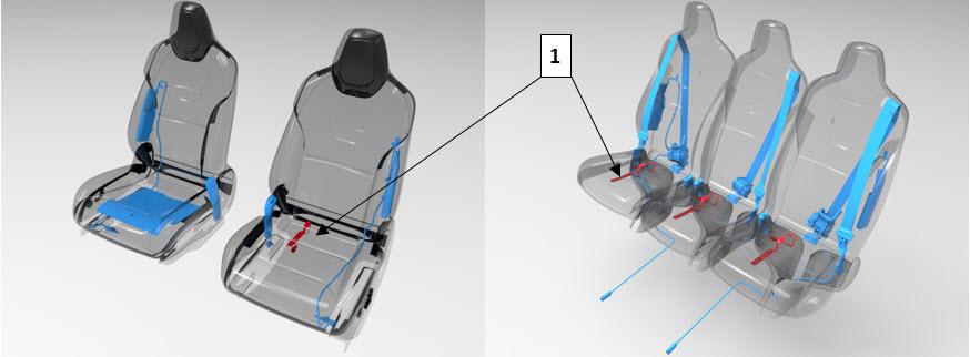
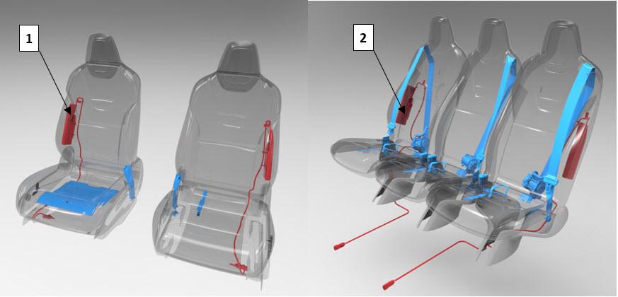
Seat Belt Pretensioner (First and Second Row)link
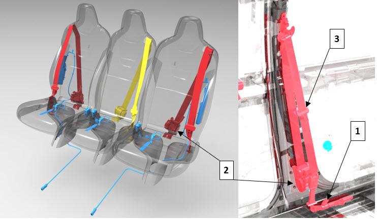 |
|---|
| 1. Lap belt pretensioner 2. Shoulder belt retractor and pretensioner 3. Seat belt buckle |
| Seat Belt Pretensioner (First and Second Row) |
The driver and first row passenger seat belt pretensioners are a dual pretensioner system. The lap belt pretensioners are mounted on the body sill side, and the shoulder belt pretensioners are integral with the retractors. The outboard second row seats each have a single shoulder pretensioner. The initiators of all pretensioners are part of the seat belt pretensioner deployment loop and always deploy simultaneously.
Anytime an airbag deployment occurs, the seat belt pretensioners are also deployed. These devices are designed to work together to safely absorbed occupant energy. In the case of a rear impact where airbags are not deployed, the pretensioners deployment is responsible for absorbing all the occupant energy. The pretensioners will not be deployed if the corresponding seat belt buckle signal is unlatched. If the signal is not available or faulted at the time of deployment, it is assumed that the seat belts are buckled and the pretensioners will be fired.
The RCM directs current through the deployment loops to the initiator. Current passing through the initiator ignites the material in the canister, producing a rapid generation of gas. The gas produced from this reaction deploys the seat belt pretensioners, which remove slack in the lap and/or shoulder belts. The process only occurs once and cannot be reversed. The component needs to be replaced after every deployment.
Steering Columnlink
 |
|---|
| 1. Driver airbag 2. Steering column carrier 3. Tilt motor 4. Telescopic motor 5. Steering shaft |
| Steering Column |
The steering column is designed to absorb energy and collapse during frontal collisions to decrease the chance of injury to the driver. A deformable wire adds resistance to the collapsing motion. If the vehicle has been in a collision that caused driver airbag deployment, the column should be inspected to check whether or not it collapsed.
Warning
The steering column must be inspected whenever the driver airbag has deployed. For inspection instructions, refer to Collision Repair Procedure SRS Inspection and Component Replacement.
Clockspringlink
The clockspring is encapsulated into a plastic cassette, which is contained within the Steering Column Control Module (SCCM). The cassette consists of an outer and inner housing with integral connectors that contain a flat ribbon flexible cable with 4 wires carrying out the following functions:
- Positive feed to the inflator module, Stage 1 and 2
- Ground to the inflator module, Stage 1 and 2
Airbag Indicator Lightlink
The airbag indicator light, located in the instrument cluster, is used to notify the driver of TSRS malfunctions and to verify the RCM is communicating with the instrument cluster. The RCM is powered in accessory mode and higher. The instrument cluster momentarily turns on the airbag indicator light. While the indicator is on, the RCM conducts tests on all TSRS components and circuits.
A TSRS malfunction could result in non-deployment of the airbags or deployment in conditions less severe than intended. The alerts broadcasted on the Chassis CAN indicate the failed component in the system. The TSRS airbag indicator remains ON until a successful startup and system check has been completed. Search for the alert in Toolbox to verify if a certain fault will latch the light on or will allow it to be cleared during a drive cycle.
Pedestrian Warning Systemlink
 |
|---|
| Pedestrian Warning Speaker in Vehicles Built Before September 2020 |
 |
|---|
| Vehicles built after September 2020 have a bracket so the new speaker can fit on the front fascia. |
| Pedestrian Warning Speaker in Vehicles Built After September 2020 |
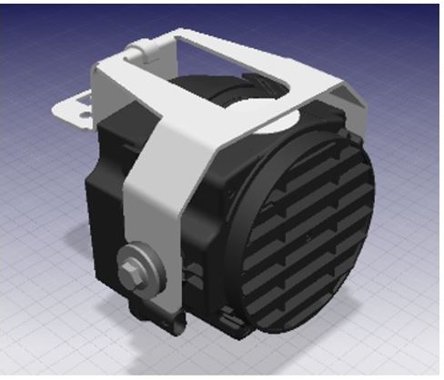
The Pedestrian Warning System (PWS) encompasses a speaker enclosed in a box at the front LH side of the vehicle, located on the front fascia. The PWS is a legal requirement based off region, and the specifics of the requirement (pitch of noise, speed of vehicle, etc.) is dependent on which region the vehicle is located. Electric vehicles traveling at slow speeds must emit a noise to warn pedestrians of motion. As soon as a vehicle is put into gear, the speaker emits a noise. Vehicles in the APAC market, except for Japan, have the ability to turn off the PWS.
Drive
The speaker emits a noise while the vehicle is in Drive. As the vehicle accelerates, the noise goes up in pitch. Once the vehicle reaches a speed of 19mph (30kph), the noise begins to fade out. The forward motion noise sounds similar to a spinning fan, and Tesla has taken precautions to minimize the noise for customers inside the vehicle as the intent is that the PWS is only heard from outside the vehicle.
Reverse
When the vehicle is in Reverse, the noise emitted by the PWS needs to be heard at the rear of the vehicle. Since the speaker is located at the front of the vehicle, the noise for reverse is increased and can be heard within the vehicle. The sound emitted while in Reverse is more of a tone and intentionally sounds different than the noise while in Drive. No matter what the speed is, the PWS will emit a noise while in Reverse.
As of September 2020, the United States requires all new electric vehicles to be equipped with the PWS. With this new requirement, Tesla improved the system to be less noticeable for customers within the vehicle. Vehicles built prior to September 2020 have the potential to hear the PWS while within the vehicle.
Communication
The PWS receives messages via the UI. The drive inverter reports the gear and speed of the vehicle to the gateway. The gateway then communicates this information to the UI where the audio system then transmits the appropriate noise based on these inputs. The audio system in the vehicle includes microphones and amplifiers that then communicate to all of the speakers. If there are issues with the PWS, a good first debug step would be to inspect the other speakers in the vehicle to pinpoint if the issue is with the audio system as a whole or specifically the PWS.
Service & Diagnosticslink
Gateway Configurationslink
| Config | Value | Key | Description |
|---|---|---|---|
| pedestrianWarningSound | 0 | NONE | No pedestrian warning sound available |
| 1 | SPEAKER | Pedestrian warning sound emitted from discrete speaker | |
| 2 | EXT_SPEAKER_V2 | Pedestrian warning sound emitted from 2nd generation exterior speaker | |
| restraintsHardwareType | 101 | NA_MXP2 | North America for Model X (2021+) |
| 102 | EUROW_ECALL_MXP2 | Europe/ROW with eCall for Model X (2021+) with far side airbag | |
| 103 | NA_MXP2_FSAB | North America Model X (2021+) with far side airbag | |
| 104 | NA_MXP2_YOKE | North America Model X (2021+) with yoke steering wheel | |
| 105 | EUROW_ECALL_1_STG_DAB_MXP2 | Europe/ROW for Model X (2021+) with 1-stage drive airbag |
ODIN routineslink
| Routine | Description |
|---|---|
| PROC_RCM_X_SERVICE-TASKS | This routine can be run via Toolbox and runs through all the individual self tests on each of the safety components, as well as any calibration / configuration routines necessary for the RCM. |
| TEST-BASH_SPK-BASE_X_PED-WARN | External Amplifier + External Microphone Connection Check |
| TEST-BASH_SPK_X_PWS-CHECK | Check the electrical connection between the MCU and the Pedestrian Warning Speaker |