Model X Thermal HVAC Systemlink
Last updated: October 20, 2023
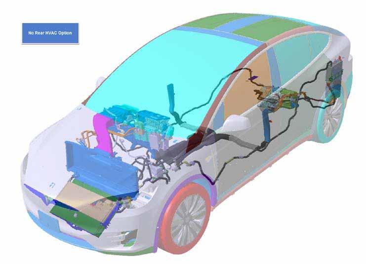
Component Locationlink
 |
|---|
| Without Rear HVAC |
 |
|---|
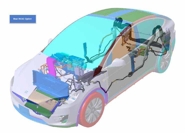
| With Rear HVAC |
 |
|---|
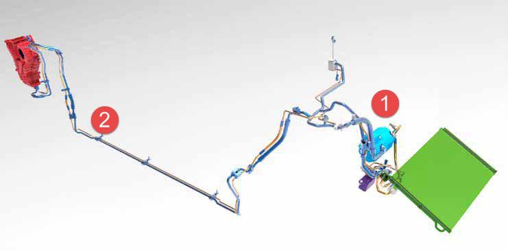
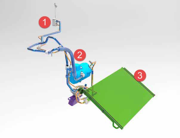
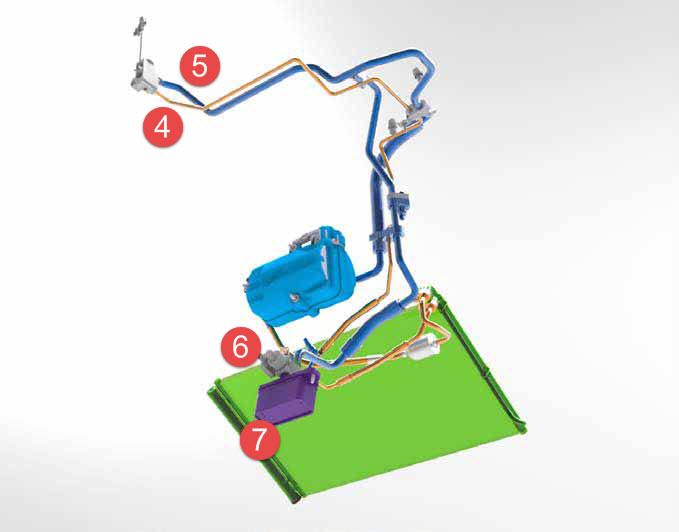
| Component overview |
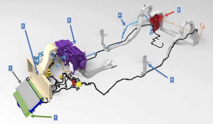
| 1. Coolant radiator 2. HEPA filter 3. Front cabin HVAC unit 4. Rear refrigerant lines 5. Rear cabin HVAC unit 6. B-Pillar HVAC ducts 7. Condenser |
Overviewlink
 |
|---|
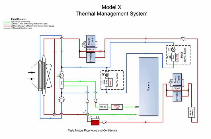
The thermal management system controls three functions:
- The flow volume, temperature, and humidity of the air in the cabin
- The battery temperature
- The temperatures of the powertrain and high voltage electronic systems
These three functions are achieved by using three subsystems:
- The cabin heating, ventilation, and air conditioning (HVAC) system
- The air conditioning (A/C) system
- The powertrain heating and cooling system
These three systems are interconnected and share many key components. Each can operate independently or together, depending on thermal requirements.
Controls for the cabin HVAC system are accessed through the vehicle’s touchscreen.
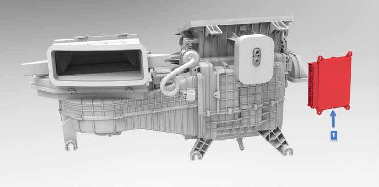
Thermal Controller (THC)link
 |
|---|
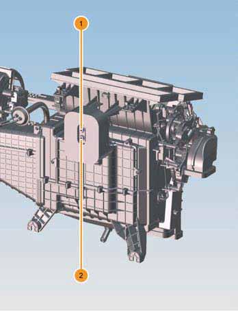
| 1. Thermal Controller (THC) |
The THC is an enclosed printed circuit board (PCB) mounted on the HVAC unit.
The THC receives the following direct inputs:
- Coolant temperature
- Refrigerant pressure and temperature
- Coolant level
The THC controls the following outputs:
- A/C compressor
- TXV solenoids
- Condenser fan controllers
- Coolant pumps
- Coolant diverter valves
- Active louvers (radiator/condenser air flow control)
- Positive Temperature Coefficient (PTC) heater demand
- Coolant heater demand
The THC receives feedback from the following components:
- A/C compressor: Energy consumption, faults
- Coolant heater: Temperature
- Coolant pumps: Speed, faults
- Coolant diverter valves: Position
The THC reads the following data from the CAN network:
- Vehicle speed
- Charge status
- Drive unit temperatures
- Battery temperatures
- Charger temperatures
- PTC heater: Temperature, duty cycle feedback, faults
- Remote Climate Control Module (RCCM) HVAC requests, ambient and duct temperatures, door actuator voltages, faults
From this information, the THC provides the appropriate responses to control these devices, as well as prioritizing compressor demand between the needs of the in-vehicle evaporator and the needs of the battery coolant chiller.
The THC also receives and interprets diagnostic information and fault codes. This information is reported to the Gateway controller via the powertrain CAN bus.
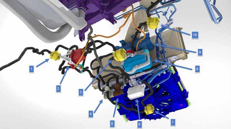
Battery and Powertrain Cooling and Heatinglink
 |
|---|
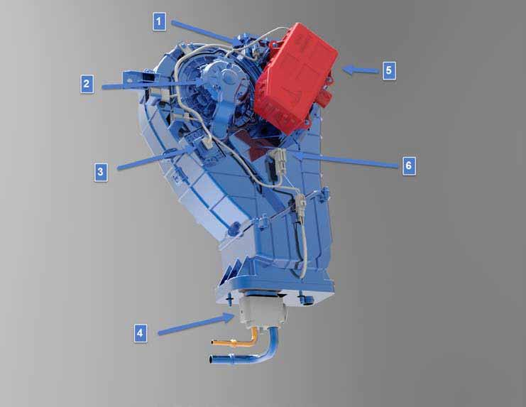
| 1. Powertrain coolant pump 2 2. Battery coolant heater 3. Battery coolant pump 2 4. (Series / Parallel) mode coolant valve 5. Radiator bypass valve 6. Battery chiller 7. Battery coolant pump 1 8. A/C compressor 9. Coolant reservoir 10. Powertrain coolant pump 1 |
The heating and cooling system includes a radiator, hoses, coolant pumps, and valves arranged to provide heating and cooling to the powertrain components and the High Voltage (HV) Battery. The coolant can circulate in series mode or parallel mode. Series mode configures the cooling system so that the HV Battery and powertrain are heated or cooled in series, with heat transfer occurring between the two subsystems. In parallel mode, the HV Battery and powertrain loops run separately and do not appreciably transfer heat between the two systems.
The dual function system incorporates a four-way coolant diverter valve with two inlets and two outlets that can switch coolant routing.
Powertrain Heating and Cooling Modeslink
The following modes are available for powertrain heating and cooling requirements. The system automatically implements the most appropriate mode according to the prevailing conditions.
-
Series Mode - Battery Heating
Series mode is used during cold soak conditions. Coolant flows through the motor in order to heat it, bypasses the radiator and then flows into the HV Battery for warming the battery cells. If additional heating is required, the battery coolant heater is activated to provide additional heat to the coolant before it enters the HV Battery.
-
Series Mode - Reduced Cooling Energy
Series mode is also an effective configuration when used in mild ambient temperatures. This allows cooling of the HV Battery and powertrain using only the radiator, without the need for operating the A/C compressor and chiller system for HV Battery cooling.
-
Series Mode - High Ambient Powertrain Cooling
In extremely hot conditions when the radiator cooling of the powertrain is limited, the HV Battery can act as a thermal capacitor to absorb powertrain heat and allow the motor to run cooler, improving motor efficiency. It is only effective until the HV Battery temperature reaches its thermal limits. To extend high temperature operation, the chiller and A/C compressor can be engaged to chill coolant going to the Battery and the powertrain components.
-
Parallel Mode
Parallel mode allows the most efficient use of the radiator for powertrain cooling, because the powertrain coolant can run at much higher temperatures than the Battery coolant. This mode also allows the Battery to heat itself gradually so that it does not require active cooling, even if it absorbed significant amounts of powertrain waste heat. Also, if the Battery requires cooling but the powertrain does not, the battery coolant chiller system can be activated solely to cool the HV Battery. During charging, the charger is cooled on the powertrain cooling loop. Operating in parallel mode allows this to happen without adding heat to the HV Battery.
Componentslink
Series/Parallel Mode Valvelink
 |
|---|
The series/parallel mode valve is a 4-way valve that is controlled by the THC. It contains a position sensor that the THC monitors for comparing desired valve position to actual. It is used to switch the coolant flow path from going through the HV Battery and powertrain in series, to diverting the coolant flow path into two parallel loops. The Battery loop consists of the HV Battery, DCDC converter, chiller, and coolant heater. The powertrain loop consists of the charger, the drive unit(s), the radiator, and the coolant reservoir.
The THC can select two paths for coolant flow through the system. In series mode, coolant flows through the Battery and powertrain in a continuous loop. If the temperature of the HV Battery is below nominal, heat from the powertrain can be used to passively raise the temperature of the Battery. The major advantage of this strategy is that it does not require additional energy to actively heat the HV Battery using the coolant heater. If the temperature of the HV Battery must be managed independently, the THC commands the valve to the parallel mode position. In parallel mode, the HV Battery is isolated from the powertrain coolant loop, and can be actively cooled without being affected by powertrain temperature fluctuations.
Note
Refer to Mode Valve Diagnostics section for more information.
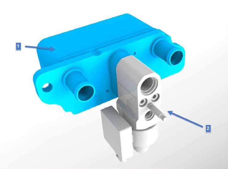
Coolant Chillerlink
 |
|---|
| 1. Coolant chiller 2. EXV |
The coolant chiller is a refrigerant-to-coolant heat exchanger that is located under the hood and mounted on a bracket integral with the front subframe. The coolant chiller is used for active cooling of the HV Battery and DCDC converter. It can also support cooling of the drive units (motor, gearbox, and inverter) and power electronics.
The coolant chiller is fitted with an EXV on the inlet and outlet ports and is serviced as an assembly.
The EXV is composed of only one electronic controlled moving valve needle. The THC sends a LIN Signal to the EXV to control the flow of refrigerant into the chiller.
Note
Refer to EXV diagnostics section for more information.
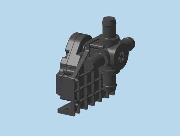
Coolant Bypass Valvelink
 |
|---|
| 1. Bypass valve |
The thermal management system has one coolant bypass valve for the radiator. It is directly controlled by the THC, and has position sensors that the THC monitors for comparing each desired valve position to the actual position.
The radiator bypass valve is mounted behind the condenser fan. The THC commands the valve to the full radiator position if the system is in parallel mode, or if it is in series mode and either:
- The HV Battery inlet temperature is greater than the HV Battery active cooling target.
- The powertrain inlet temperature is greater than the powertrain active cooling target
The THC commands the valve to the full bypass position when:
- The HV Battery heater is commanded on.
- The HV Battery AND powertrain passive cooling target is 10 degrees C greater than the inlet temperature.
Note
Refer to Appendix C: Bypass Valve Diagnostics for more information.
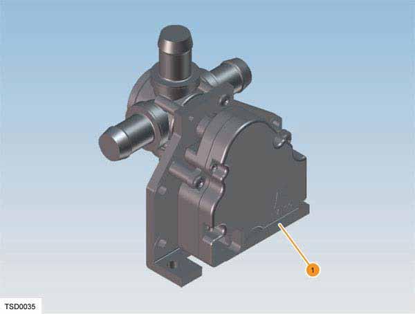
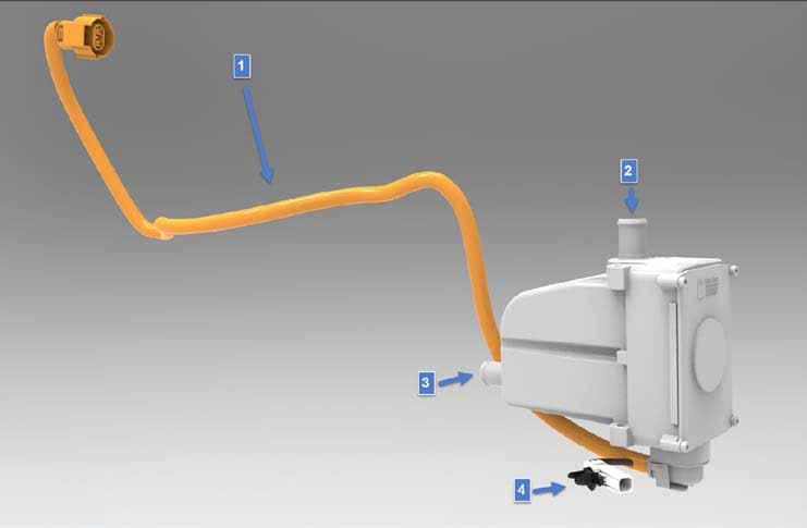
Coolant Heaterlink
 |
|---|
| 1. Coolant heater 2. Coolant inlet 3. Coolant outlet 4. Coolant temperature sensor |
The coolant heater is located under the hood near the bulkhead. The purpose of the coolant heater is to heat the battery coolant to a minimum temperature determined by the Battery Management System (BMS). The coolant heater is controlled by the THC via the Forward Junction Box (FJB). High voltage is supplied directly from the FJB. The coolant heater HV fuse is located inside the FJB.
The coolant heater has a sensor on the bottom of the heater that monitors the internal coolant temperature and reports this information to the THC to prevent overheating.
Note
Refer to Coolant Heater Diagnostic section for more information.
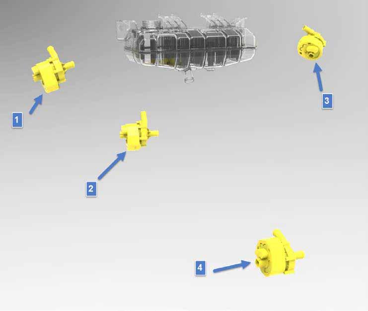
Coolant Pumpslink
 |
|---|
| 1. Powertrain (PT) coolant pump 1 2. Battery (Bat) coolant pump 2 3. Powertrain (PT) coolant pump 2 4. Battery (Bat) coolant pump 1 |
The Model X has four coolant pumps: two battery coolant pumps and two powertrain coolant pumps.
The four coolant pumps are identical brushless 12V DC centrifugal pumps. All the pumps are controlled by the THC.
In Parallel Mode:
- The two battery pumps push coolant through the HV Battery based on temperature requests from the HV Battery BMS.
- The two powertrain pumps push coolant through the powertrain components to maintain them at optimum temperature based on temperature requests from each component.
In Series Mode:
- All four pumps work together to push coolant through the HV Battery and powertrain components.
Note
Refer to Appendix E: Coolant Pump Diagnostics for more information.
Coolant (Glycol) Temperature Sensorlink
There are two coolant temperature sensors. One is in-line between the coolant heater and the Battery, and provides the HV Battery inlet coolant temperature to the THC. The other is in-line at the front drive unit inlet and provides powertrain inlet coolant temperature to the THC. Both of these sensors are the same Negative Temperature Coefficient (NTC) sensors.
Note
Refer to Appendix F: Coolant Temperature Sensor Diagnostics for more information.
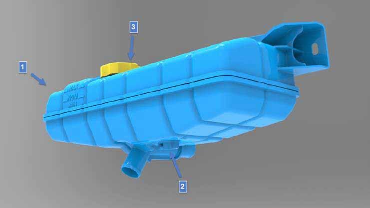
Coolant Reservoir Assemblylink
 |
|---|
| 1. Coolant reservoir 2. Coolant level sensor location 3. Pressure cap |
The coolant reservoir is mounted under the hood and contains a coolant level sensor that indicates to the THC that the coolant level is low. The reservoir is a flow-through de-gas bottle. The majority of the coolant flows past the bottle, while a small portion of the coolant stream flows into the bottle. The coolant that does flow into the bottle passes through a series of settling chambers that allows air to migrate out of the coolant within several minutes. Air-free coolant is then drawn from the reservoir. The coolant level should be between the Nominal and Maximum lines when the vehicle is at ambient temperature.
Coolant Level Sensor diagnostics:
- The level sensor is a switch that is opened or closed based on the magnetic float position in the coolant reservoir.
- The switch is closed when the coolant level is above the “MIN” line on the coolant reservoir.
- The switch is open and the THC sets the low coolant warning when the coolant level is below the “MIN” line on coolant reservoir (less than 1.3L of coolant in the reservoir).
Note
Refer to Appendix 1: Coolant Reservoir Specifications for more information.
Coolantlink
The coolant used is G-48 coolant, supplied pre-mixed 50/50 concentration with distilled water. G-48 is a long-life coolant designed for high aluminum content powertrain systems.
Warning
Do not top off or refill the cooling system with any other type of coolant.
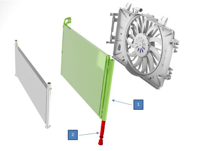
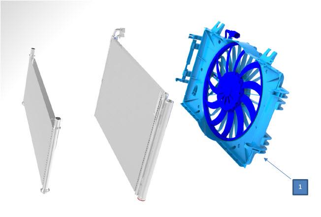
Active Shutterslink
 |
|---|
The Model X has one radiator/condenser assembly. The shutter assembly is visible from the front of the vehicle, and is located in front of the cooling module.
The active shutters control the flow of ambient air through the radiator and condenser. The system is designed to keep airflow at the minimum necessary for cooling. Also, minimizing airflow can be used to reduce the time for components to reach normal operating temperature.
The active shutters also minimize the vehicle’s aerodynamic drag when cooling demands are low, reducing vehicle power requirements and increasing range. The active shutters close when the vehicle is switched off, but re-open if required to cool the vehicle’s charging system during the charge sequence.
The active shutters are motor actuated. The motor is controlled via a Local Interconnect Network (LIN) signal from the Thermal Controller (THC), using feedback from the following:
- Coolant temperature sensors
- Refrigerant temperature sensor
- Refrigerant pressure sensor
- Ambient air temperature sensor
- Vehicle speed sensor
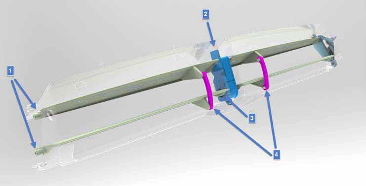 |
|---|
| 1. 4 shutter blades 2. Shutter actuator 3. Drive connection to bottom shutter blades 4. Connecting pins between top and bottom shutters |
Shutter Operationslink
- Shutter Assembly Cold Temperature Operation:
- Driving: The shutters are closed to maximize HV Battery warming. Aerodynamic drag is reduced to extend the vehicle driving range.
- Charging: The shutters are closed to maximize HV Battery warming.
- Shutter Assembly Normal Temperature Operation:
- Driving: The shutters open if the powertrain or HV Battery need to be cooled. The shutters also open if A/C is turned on, to provide airflow to the condenser. At low speeds, the shutters might also open if additional airflow is required to the condenser.
- Charging: The shutters open if the HV Battery and / or charger need to be cooled.
- Shutter Assembly High Temperature Operation
- Driving: The shutters open as the powertrain or HV Battery need to be cooled. The shutters also open if the A/C is turned on or for active HV Battery cooling (battery coolant chiller on) during aggressive driving.
- Charging: The shutters open if the HV Battery and / or charger(s) need to be cooled. The shutters also open if the A/C is turned on or for active HV Battery cooling (battery coolant chiller on) during supercharging.
Cabin HVAClink
Componentslink
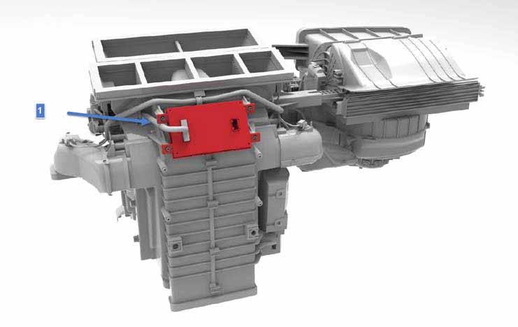
Remote Climate Control Module (RCCM)link
 |
|---|
| 1. Remote Climate Control Module (RCCM) |
The RCCM is an enclosed Printed Circuit Board (PCB) that is mounted on the HVAC box and receives signals from the following sensors:
- Ambient air temperature
- In-vehicle air temperature
- Evaporator temperature
- Vent, Floor, and Defrost duct temperature
- Defrost, Mode, Blend, Driver / Passenger Temp, and Intake door positions
The RCCM also commands the following components in the HVAC box:
- Blower motor speed
- Defrost, Mode, Blend, Driver / Passenger Temp, and Intake door positions
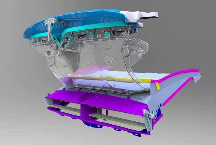
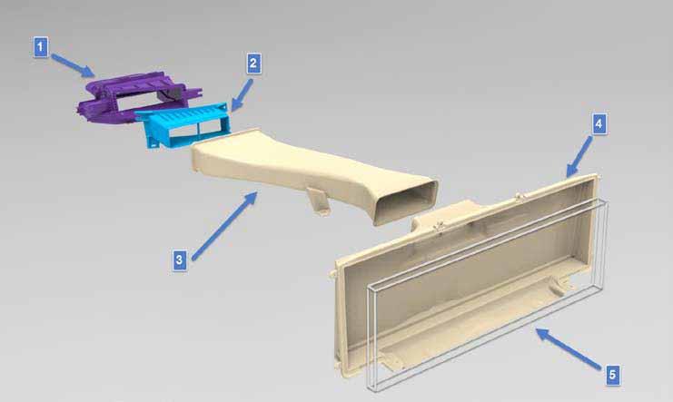
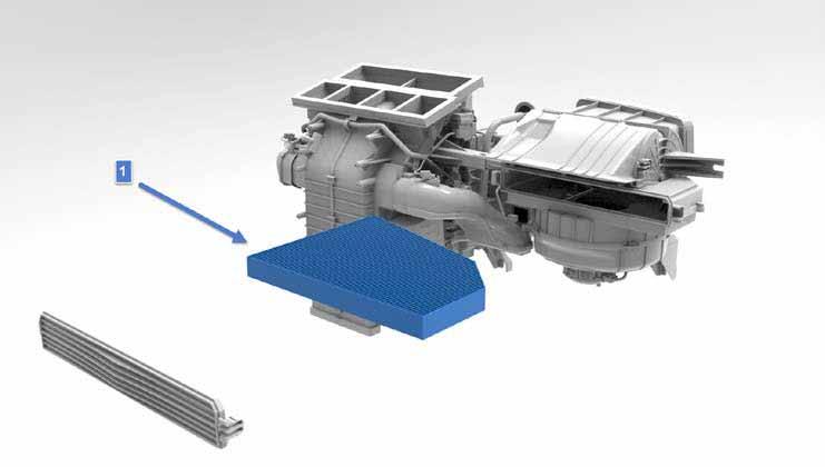
HEPA Filter, Recirculation Filter, and Filter Housinglink
 |
|---|
| 1. Front HVAC box air inlet 2. Fresh air inlet housing 3. Fresh air inlet duct 4. HEPA filter housing 5. HEPA filter |
 |
|---|
| 1. Charcoal filter |
The Recirculation (Recirc) carbon filter helps clean the air inside the cabin and reduce odors. Fresh air goes through both the HEPA and Recirc filter before reaching the cabin. This serviceable filter is located about the HVAC blower motor behind the glove box.
Cabin Air Distributionlink
Ventslink
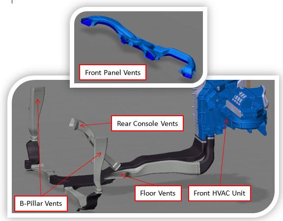 |
|---|
The cabin HVAC system controls the temperature, humidity, flow volume, distribution, and quality of air within the vehicle to achieve and maintain the conditions requested by the driver.
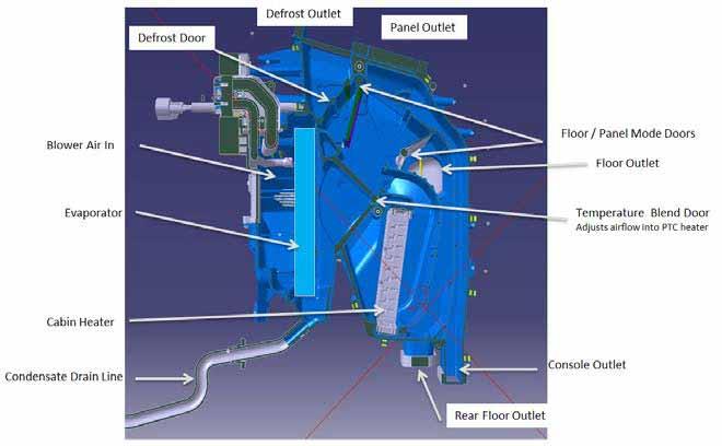
Air is drawn into the HVAC unit by the integral blower motor located above the passenger footwell. The air is then forced into the HVAC unit through an expansion duct to the evaporator. The evaporator cools and dehumidifies the air and transfers it to the Positive Temperature Coefficient (PTC) heater.
After cooling and dehumidifying as necessary, the air passes to a split temperature blend door operated by two actuators. The actuators are controlled by the RCCM. This diverts air through or around the cabin heater depending on the temperature of air required at the outlet ducts. A set of air distribution doors in the HVAC unit directs the conditioned air to the distribution outlets. The outlets from the HVAC unit include the defrost outlet, the four panel outlets, two front floor outlets, two rear floor outlets, and two rear console outlets. Each front outlet has temperature sensors to provide feedback for temperature control. Rear floor and rear console outlets do not have sensors.
The driver and passenger temperature blend doors are located between the evaporator and the PTC heater. In dual zone temperature split mode, the single PTC heater cannot run as large of temperature difference between driver and passenger sides as is possible with an internal combustion engine’s heater core, due to the possibility of overheating the single PTC heater.
HVAC Unit(s)link
Front HVAC Unitlink
 |
|---|
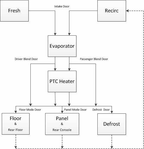 |
The Recirculation and Fresh air modes allow air to be drawn into the cabin HVAC unit from inside the vehicle in Recirculation mode, or from outside the vehicle in fresh air mode. The driver can select Recirculation mode to avoid traffic fumes being drawn in from outside. Recirculation also maximizes heating and cooling by using conditioned Recirculated air. Various automatic control modes adjust the percentage of Recirculated and outside air to give the most efficient operation while providing optimum comfort and humidity control. The recirculation logic is tuned for front passenger comfort only, since this logic provides the most efficient HVAC operation.
If windows begin to fog, select Outside Air mode. If Outside Air mode is not sufficient to reduce fogging, select Defrost mode.
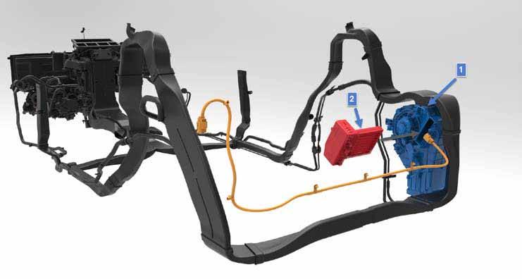
Rear HVAC Unitlink
The rear HVAC unit is an optional feature. The rear HVAC unit is similar to the main front HVAC unit, but is much more compact. An evaporator and TXV are installed in the unit, supplied with refrigerant from the front of the vehicle through refrigerant lines located on the RH sill panel. The PTC heater is built in. A blower fan circulates the air. Sensors are available for temperature feedback. The rear HVAC unit increases heating/cooling capacity and makes the third row and second row more comfortable.
 |
|---|
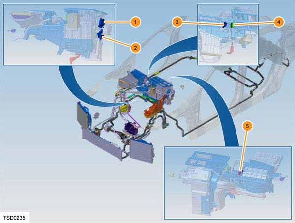
| 1. Rear Duct Temperature Sensor 2. Rear Blower fan 3. Rear Blower motor FET 4. Rear TXV 5. Rear PTC heater 6. Rear Evaporator Temperature Sensor |
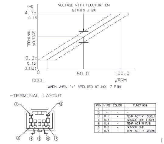
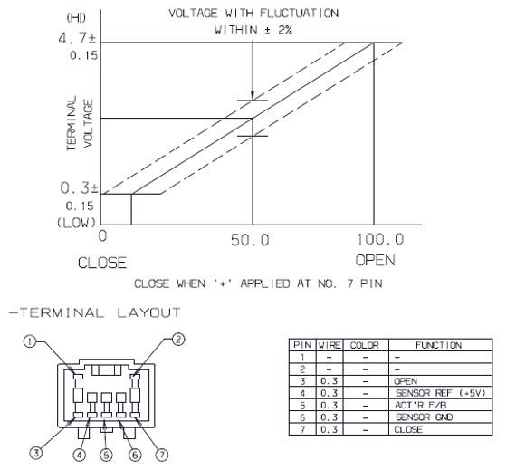
HVAC Unit Door Actuatorslink
 |
|---|
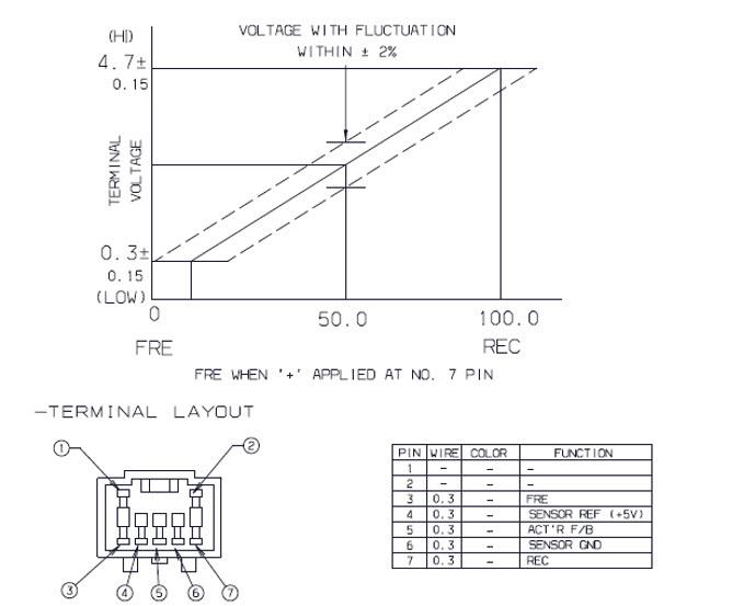
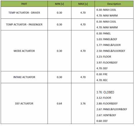
| 1. Mode actuator 2. Driver air temperature actuator 3. Passenger air temperature actuator 4. Defrost air actuator 5. Intake air actuator |
- The mode and defrost actuators change the position of mode doors to** | direct airflow to the panel, floor and defrost modes.
- The driver and passenger each have blend door actuators that change the position of the driver and / or passenger blend doors to adjust the temperature of the vented air.
- The intake actuator changes the position of the inlet air between Fresh and Recirc.
- The RCCM drives the HVAC actuators by applying 12V to each respective pin depending on which direction the actuator is being commanded. The HVAC actuators provide a voltage feedback signal to the RCCM for position information.
Note
Refer to Appendix K: Actuator Diagnostics for more information.
HVAC Unit – Airflow Distribution Targetlink
| Mode | Panel | Panel / Floor | Floor | Floor / Defrost | Defrost |
|---|---|---|---|---|---|
| Outboard Panel Outlets | 38 | 22 | 10 | 10 | 10 |
| Inboard Panel Outlets | 38 | 22 | 0 | 0 | 0 |
| Rear Console Panel | 14 | 12 | 0 | 0 | 0 |
| Front Floor Outlets | 5 | 22 | 30 | 25 | 10 |
| Rear Floor Outlets | 5 | 22 | 30 | 25 | 10 |
| Defrost Outlets | 0 | 0 | 30 | 40 | 70 |
| Total % | 100 | 100 | 100 | 100 | 100 |
Note
Refer to Appendix L: HVAC Unit Actuator Targets for more information.
Air Quality Sensorlink
The Air Quality Sensor is added to analyze fresh air intake into the cabin for pollutants. The THC reads this sensor data and switches the cabin control setting to Recirc mode if polluted air is detected. After a timeout period, it will switch back to Fresh air mode. This will occur if the vehicle is left in automatic climate mode and can be overridden. The sensor is mounted to the outside of the front ducting under the vehicle front logo.
 |
|---|
| 1. Air Quality Sensor |
Positive Temperature Coefficient (PTC) Heater(s)link
Front PTC Heaterlink
 |
|---|
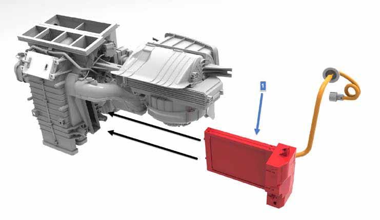
| 1. Front Positive Temperature Coefficient (PTC) heater |
The PTC heater is a high voltage heating device using ceramic heating stones as resistors. The electrical resistance of the stones increases as their temperature rises. This provides a mechanism to prevent overheating. The heater consists of a heating matrix including the heating stones, a conductive plate, and aluminum fins. The controller is mounted in a housing connected to the matrix and supplies the high voltage power to the heating stones. The controller uses six sets of Insulated Gate Bipolar Transistor (IGBT) circuits to switch the DC power. A pulse width modulation circuit provides variable power to regulate the amount of heat generated.
The PTC heater is on the Body Fault-Tolerant (BFT) CAN bus. The THC sends a duty cycle request via the CAN bus to the PTC heater. The THC limits the PTC heater duty cycle in the case of low HV power, Range drive mode, and end of charge taper for the HV Battery.
The PTC heater uses four internal temperature sensors for internal temperature limiting. Two sensors are on the heating grid, and two more are located on the drive IGBTs. If any of these sensors faults, the PTC does not operate. The PTC also does not operate if it does not receive correct signals from the RCCM's discharge air temperature sensors (floor, vent, and defrost).
High voltage to the PTC heater is supplied directly from the Forward Junction Box (FJB). The PTC heater 40A fuse is located inside the FJB.
Rear PTC Heaterlink
 |
|---|
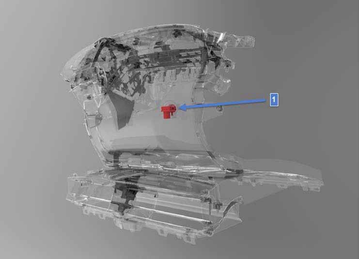
| 1. Rear HVAC box 2. Rear PTC heater |
A second PTC heater is included with the rear HVAC option. This PTC heater is located in the rear HVAC unit and supplies heated air for the third row and second row on the C pillar and B pillar, respectively. Operation is similar to the front, though it is approximately 50% smaller and has approximately 50% less power consumption. The high voltage connector is located at the heater and includes an HVIL bridge pin. This PTC heater is on the thermal (TH) CAN bus.
Sensorslink
Ambient Air Temperature Sensorlink
The ambient air temperature sensor, located in front of the coolant radiator, is a negative temperature coefficient (NTC) sensor. This sensor is directly connected to the RCCM, which broadcasts both raw and filtered ambient temperature to the THC. The filtered temperature is displayed on the touchscreen for driver information.
Note
Refer to Appendix G: Ambient Air Temperature Sensor Diagnostics for more information.
In-vehicle Temperature Sensorlink
The THC is hard-wired to two in-vehicle temperature sensors. They are both NTC sensors. One sensor is located in the driver B-pillar cap and the other sensor is located in the passenger B-pillar cap.
Note
Refer to Appendix H: In-vehicle Temperature Sensor Diagnostics for more information.
HVAC Discharge Air Duct Temperature Sensorlink
The discharge air duct temperature sensors monitor the temperature of air flowing through the driver and passenger discharge air ducts, providing feedback to the RCCM. The RCCM then transmits this temperature sensor information to the THC. The THC compares the actual discharge air temperature to the calculated discharge temperature target and adjusts the A/C compressor duty cycle, PTC heater duty cycle, and HVAC blower speed in order to maintain the desired cabin temperature.
Evaporator Outlet Temperature Sensorlink
The evaporator outlet temperature sensor is a NTC sensor that extends into the airflow on the outlet side of the evaporator. It provides the RCCM with a temperature signal that it sends to the THC, which the THC uses to control the requested RPM of the A/C compressor, and thus the operating temperature of the evaporator. The RCCM supplies the evaporator temperature sensor with a 5V reference voltage and translates the return signal voltage into a temperature. If the sensor develops a fault, the RCCM adopts a default temperature of 0°C (32°F).
Note
Refer to Appendix I: Evaporator Outlet Temperature Sensor Diagnostics for more information.
Rain/Light/Solar (RLS) Sensorlink
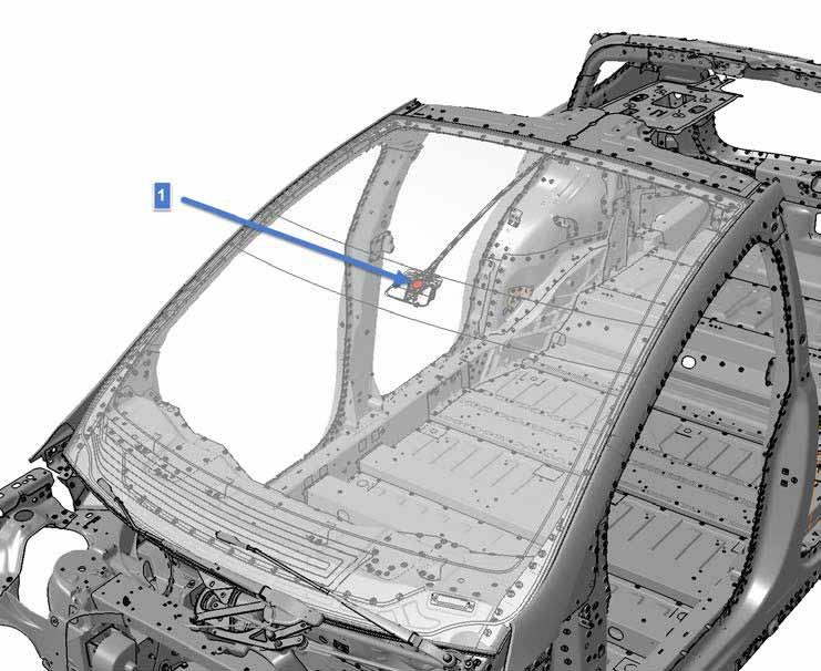 |
|---|
| 1. Location of the RLS sensor |
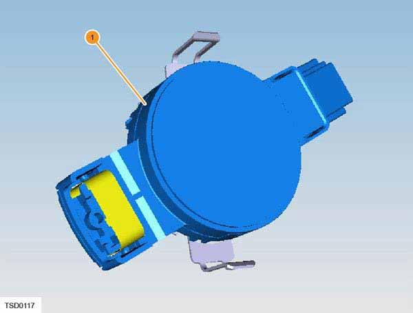 |
|---|
| Early RLS sensor |
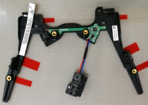 |
|---|
| Later RLS Sensor |
The rain/light/solar (RLS) sensor is located on the windshield, in a housing directly in front of the rear view mirror. Holes in the housing allow air to flow through the sensor. It is connected to the central body controller via a LIN communication circuit. The central body controller broadcasts data from the RLS sensor on the body CAN bus to the Gateway, which then puts the data on the fault-tolerant body CAN bus for use by the THC.
The THC uses solar load information from the RLS sensor to estimate the heating effect on the vehicle from sunlight. It uses this input to maintain the desired cabin temperature as the solar load varies.
The THC also uses the cabin humidity and windshield temperature data from the RLS sensor for windshield fogging detection. If conditions for windshield fogging are detected, the THC attempts to reduce fogging by forcing fresh air, turning on partial defrost mode, and turning on the air conditioning. If the vehicle is in a severe fogging condition, the driver might still need to select Defrost mode to provide maximum visibility.
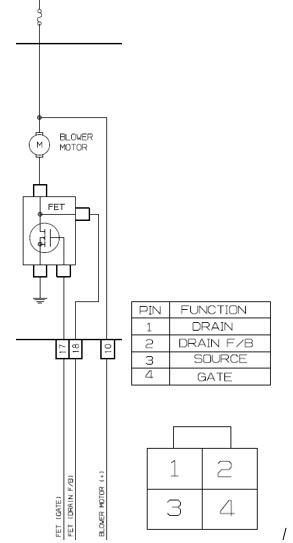
Blower Motor Control Modulelink
The HVAC blower motor speed request is sent from the RCCM as a Pulse Width Modulation (PWM) signal to the blower motor control module. The switching frequency of the module's MOSFET (FET) driver determines the voltage supplied to the blower motor, and therefore, the blower motor speed.
Note
Refer to Appendix J: Blower Motor Control Module Diagnostics for more information
Air Conditioninglink
Overviewlink
 |
|---|
| 1. Front refrigerant section 2. Rear refrigerant section |
 |
|---|
 |
| 1. Front evaporator thermal expansion valve (TXV) 2. A/C compressor 3. Condenser 4. High pressure refrigerant line 5. Low pressure refrigerant line 6. Coolant chiller electronic expansion valve (EXV) 7. Coolant chiller |
The Model X system is similar to Model S except for the following components:
- The Model X only has one condenser.
- The Model X has an optional rear HVAC unit with 3.2 kW PTC heater and evaporator core. The rear evaporator is approximately 50% the size of the front evaporator.
- The Model X rear HVAC unit includes high and low pressure refrigerant lines that run the length of the vehicle and connect the rear HVAC unit to the compressor.
- The Model X rear HVAC has a thermal expansion valve (TXV) mounted to the evaporator.
The A/C system extracts heat from inside the vehicle and transfers it to the outside atmosphere.
The Model X system includes an evaporator in the HVAC unit, a compressor, a condenser (with integrated receiver/dryer), a battery coolant chiller, a Thermal Expansion Valve (TXV) on the evaporator, and an Electronic Expansion Valve (EXV) on the chiller. All components are connected by refrigerant lines. The refrigerant lines contain high pressure and low pressure charge ports and high and low side refrigerant pressure and temperature sensors.
In addition to providing conditioned air inside the vehicle, the A/C system uses additional refrigerant lines to direct condensed refrigerant to an EXV on the battery coolant chiller assembly. This system controls the temperature of the HV Battery and the powertrain components.
An electric solenoid valve integrated into the evaporator TXV shuts off refrigerant flow to the evaporator when there is no cabin HVAC demand or if chiller demand exceeds cabin demand.
The refrigerant system is a sealed, closed-loop system. Depending on region, the system is filled with a refrigerant charge of either R-134a or HFO-R1234yf refrigerant.
A non-conductive Polyolefin Ester (POE) refrigerant oil is added to the refrigerant to lubricate the internal components of the compressor. This is supplied in the compressor during manufacture. Whenever the system is discharged and/or components are replaced, refrigerant and oil must be replaced in an equivalent weight to what was removed.
Note
Refer to the General Information > Fluids and Capacities section of the Model X Service Manual for refrigerant and oil information.
The electric A/C compressor pumps refrigerant through the system. It receives the low pressure, low temperature gas from the evaporator and/or battery coolant chiller. The gas is compressed into high pressure, high temperature vapor by the compressor. This high pressure, high temperature vapor enters the condenser and fan assembly, which cools the vapor by releasing the refrigerant heat to the ambient air. The cooler vapor transfers to the condenser, where it condenses into liquid refrigerant. As the liquid passes through a mesh filter and into the receiver/dryer inside the condenser, any moisture in the refrigerant liquid is removed by the desiccant granules. If this moisture is not removed, it can freeze and prevent normal A/C operation.
The liquid refrigerant is then transferred to the TXV and/or EXV that regulate the flow of liquid refrigerant into the evaporator or battery coolant chiller. These valves also reduce refrigerant pressure by expanding the high pressure cool liquid to a low pressure atomized spray. Liquid refrigerant spray enters the evaporator and/or the battery coolant chiller, where it absorbs heat from the surrounding area, causing the refrigerant to boil and then vaporize. This produces the cooling effect inside the vehicle. Finally the vaporized refrigerant is drawn back into the compressor and pressurized again. This repetitive cycle continues while the A/C system is operating.
Componentslink
A/C Compressorlink
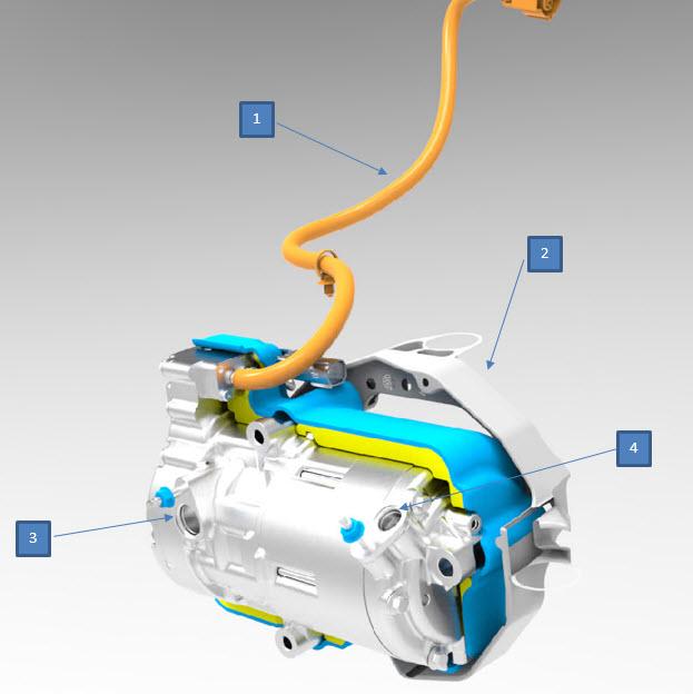 |
|---|
| 1. High voltage cable 2. Mounting bracket 3. Refrigerant suction port (low pressure) 4. Refrigerant discharge port (high pressure) |
The compressor is mounted under the hood, below the rear of the front trunk. It is a high voltage (HV) electric Direct Current (DC) scroll type pump with a maximum rotational speed of 8600 RPM.
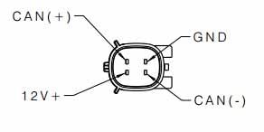
The compressor has two connectors, one for low voltage and one for high voltage. Communication with the THC is via a 500 Kbps dedicated thermal (TH) CAN bus. The low voltage connector is a four-pin connector. The signals/wires used are 12V power, ground, CAN (+), and CAN (-)
The compressor operates in any normal range of HV Battery SOC. The compressor inverter converts the CAN signal from the THC into a motor drive speed. The compressor's internal 12V power supply is generated from the HV input. The low voltage harness connections to the vehicle are used for communication only. If HV is not present at the compressor, there is no communication response.
High voltage is supplied directly from the Forward Junction Box (FJB). The compressor HV fuse is also located internally to the FJB.
The High Voltage InterLock (HVIL) is fitted to the FJB.
Note
The compressor contains lubricating oil. The compressor must be kept upright at all times to retain this oil in the sump.
Warning
Use of an incorrect oil might affect the dielectric strength of the motor and cause an internal short circuit, as well as affecting bearing life.
Note
Refer to Appendix M: A/C Compressor Diagnostics section for more information.
Condenserlink
The Model X uses one condenser. The refrigerant enters the condenser as gas refrigerant and exits the single condenser as sub-cooled refrigerant.
The condenser dissipates heat from the refrigerant to the air being forced through it. Air is forced through the condenser either by the movement of the vehicle or by operation of the condenser fan.
 |
|---|
Receiver Dryerlink
The receiver dryer’s main function is to remove moisture and contaminants from the refrigerant, but it also acts as a temporary storage area for the refrigerant. It provides a reservoir of liquid refrigerant to accommodate changes in heat load at the evaporator. Any moisture that accumulates is removed by passing the refrigerant though a desiccant bag. The refrigerant is then passed to either the TXV on the evaporator or the EXV on the battery coolant chiller.
Without the receiver dryer, any moisture in the system could form ice in the TXV or EXV, restricting the flow of refrigerant in the system.
The receiver dryer and filter is contained within the left end tank of the single condenser and is removed from the bottom.
Note
The desiccant bag in the receiver dryer is a serviceable item and must be replaced every 4 years, whenever the system is opened to ambient air for an extended time, or when an A/C system leak has been fixed.
Condenser Fan Assemblylink
 |
|---|
| 1. Condenser fan assembly |
If refrigerant cooling or radiator coolant cooling is requested when the vehicle is stationary or traveling at low speeds, the fan mounted on the condenser is activated to increase the air flow through the condenser. This increases the dissipation of heat from the refrigerant.
The Model X uses a single fan control module that is integrated into the condenser fan assembly. The control module and fan are serviced as an assembly.
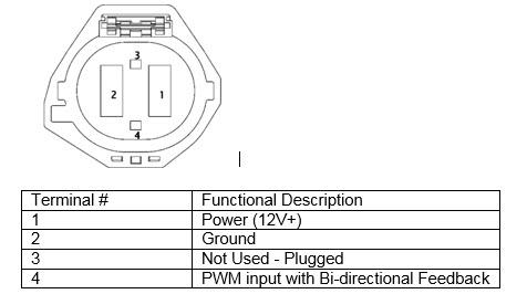
The Thermal Controller (THC) controls the fan speed via a PWM signal to the integrated fan control module on a bi-directional line. The fan control module can also respond back to the THC with diagnostic information on the same bi-directional feedback line.
Note
Refer to Appendix N: Condenser Fan Control Module Diagnostics section for more information.
Refrigerant Temperature and Pressure Sensorslink
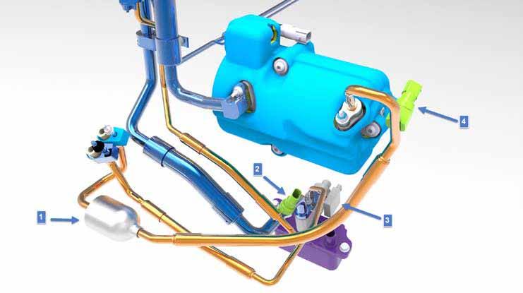 |
|---|
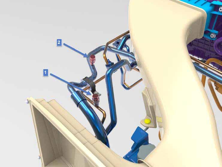
| 1. Discharge refrigerant muffler 2. Suction sensor - low temperature and pressure 3. EXV – mounted on coolant chiller 4. Discharge sensor - high temperature and pressure |
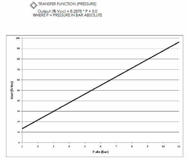
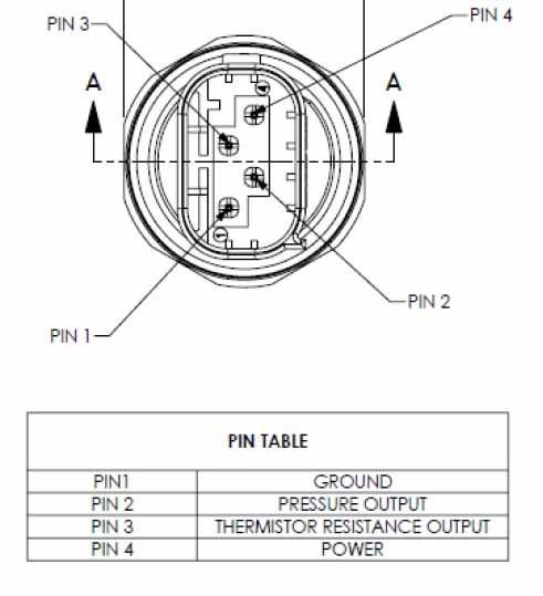
The suction sensor, located on the low pressure line leading to the compressor, measures the temperature and pressure of refrigerant on the low pressure side of the system. The discharge sensor, located in the high pressure line between the compressor and condenser, measures the temperature and pressure of refrigerant on the high pressure side of the system. The sensors communicate directly to the THC so it can control the compressor, the condenser fan speed, and the EXV position.
The suction and discharge sensors use the same electrical connector and mechanical interface to the A/C line. However, their pressure transducer calibrations are different, so the sensors are not interchangeable.
Warning
There are no Schrader valves under the transducers. Refrigerant must be recovered from the system before removing any
transducer.
Note
Refer to Appendix O: Sensor Diagnostics section for more information.
Thermal Expansion Valveslink
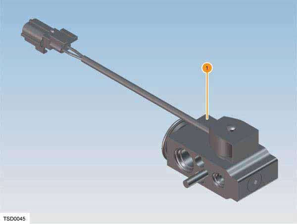 |
|---|
| 1. Thermal Expansion Valve (TXV) – Front and Rear Evaporator |
For the Model X, two expansion valves are fitted in the system (one without rear HVAC option). A TXV is fitted to the refrigerant inlet and outlet of the front and rear (if equipped) HVAC evaporator. The TXV is composed of a solenoid valve and a thermal valve. Most other brands of vehicle use expansion valves that contain only a thermal valve.
- Solenoid valve: The thermal controller (THC) sends 12V to open the solenoid valve when cabin air conditioning (A/C) is requested. The solenoid closes when the A/C is switched off. The solenoid valves on both TXVs must be open when charging the A/C system.
- Thermal valve: The thermal valve senses refrigerant temperature and pressure exiting the evaporator and uses a needle valve to control the flow of refrigerant into the evaporator. The needle valve is operated by the difference in temperature at the refrigerant outlet and inlet. The needle valve also uses a tunable spring at the bottom of the valve housing. The valve needle is attached to the charge cylinder at the top of the valve housing, which responds to the refrigerant outlet temperature. The valve is closed at low outlet temperatures and opens at high outlet temperatures to allow more refrigerant into the evaporator. The spring is set to ensure that all liquid refrigerant vaporizes before entering the evaporator.
Evaporatorlink
 |
|---|
| 1. Evaporator low pressure outlet 2. Evaporator high pressure inlet |
The evaporator is inside the HVAC unit, which is located under the dash. It cannot be removed independently of the HVAC unit.
High pressure, low temperature refrigerant changes from liquid to vapor as it enters the evaporator, and absorbs large quantities of heat as it changes state. As the air passing through the evaporator cools, moisture in the air condenses on the evaporator surface, drying the air that is delivered to the interior of the vehicle. Excess moisture collects in the bottom of the HVAC unit and is drained through a hose routed through the dash panel.
The inlet and outlet pipes of the evaporator are routed through the bulkhead, providing a mounting point for the evaporator TXV. A foam seal surrounding the TXV provides an air and water seal at the opening in the bulkhead.
Refrigerant Lineslink
Aluminum and rubber refrigerant line assemblies connect the system components together. O-rings are fitted between the connections to ensure a secure seal. To maintain a similar rate of flow around the system, the diameter of the refrigerant lines varies to suit the two pressure and temperature sections. The larger diameter hoses are used on the low pressure/low temperature section and smaller diameter pipes are used on the high pressure/high temperature section.
Service Portslink
 |
|---|
| 1. High pressure refrigerant service port 2. Low pressure refrigerant service port |
The high and low pressure service ports are located under the hood and are an integral part of the refrigerant lines. The high pressure port is on the line between the condenser outlet and evaporator inlet. The low pressure service port is on the line between the evaporator outlet and the compressor inlet.
Schrader valves form the ports in the refrigerant lines and allow connection of charging/evacuation equipment for servicing purposes. The connections are standard couplers for R134a or R1234yf. The valves are fitted with a screw-on cap to prevent refrigerant leaking through the valves and to prevent dirt from entering. Each refrigerant type requires a unique port size and associated coupler.
Warning
Servicing must only be carried out by personnel familiar with both the vehicle system and the charging and testing equipment. All operations must be carried out in a well-ventilated area away from open flame and heat sources. Refrigerant is a hazardous liquid and when handled incorrectly can cause serious injury. Suitable protective clothing, consisting of face protection, heat-proof gloves, rubber boots and apron or waterproof overalls, must be worn when carrying out operations on the air conditioning system. HVAC service mode must be initiated using Toolbox before any evacuation and recharge procedures are performed. Refer to the applicable Service Manual procedure.
Note
Refer to the General Information > Best Practices > Air Conditioning System Precautions section of the Model X Service Manual for additional warnings and information.
Appendiceslink
Appendix 1: Coolant Reservoir Specificationslink
Model X Coolant Reservoir:
- Coolant volume in the reservoir: 3.3L
- Max coolant line: 2.8L
- Nom coolant line: 2.2L
- Min coolant line: 1.8L
- Low coolant warning: 1.3L
- Air gap between Max coolant line and cap: 0.55L
- The pressure cap is limited to 5 psig.
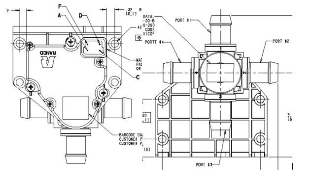
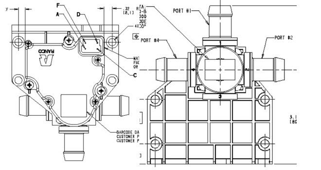
Appendix A: Mode Valve Diagnosticslink
- Pin C: Ground
- Pin A: Bat+ when THC (HVAC rail) is on
- Pin D: PWM in (run the thermal test in Toolbox to actuate the valve)
- Pin F: Feedback 0-1V (see below)
1V feedback: (Port #1 Flow to Port #4 / Port #3 Flow to Port #2)
0V feedback: (Port #1 Flow to Port #2 / Port #3 Flow to Port #4)
 |
|---|
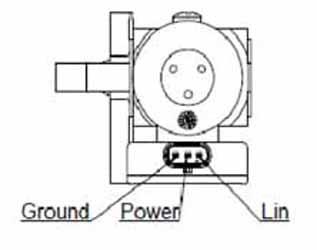
Appendix B: EXV Diagnosticslink
- Pin 1: LIN
- Pin 2: Bat+ when THC (HVAC rail) is on
- Pin 3: Ground
 |
|---|
Appendix C: Bypass Valve Diagnosticslink
Part number: 1064225-00 i44 - Pin C: Ground - Pin A: Bat+ when THC (HVAC rail) is on - Pin D: PWM in (run the thermal test in Toolbox to actuate the valve) - Pin F: Feedback (see below)
Connect pin C to GND and pin A to 12V of a 12V source.
- Apply 12V to pin D, feedback voltage should be < 3.6 V (voltage ratio > 0.9) – Port #1 Flow to Port #4
- Apply 0V to pin D, feedback voltage should be > 10.5 V (voltage ratio < 0.1) – Port #2 Flow to Port #4
*Voltage ratio = input voltage(D)/supply voltage(A)
 |
|---|
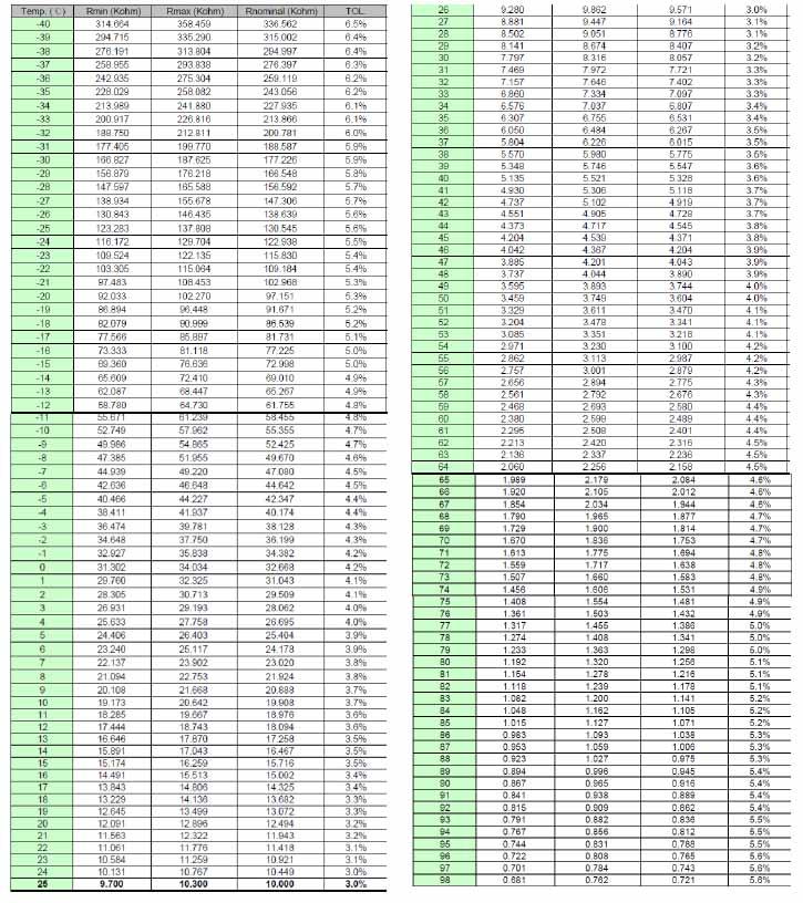
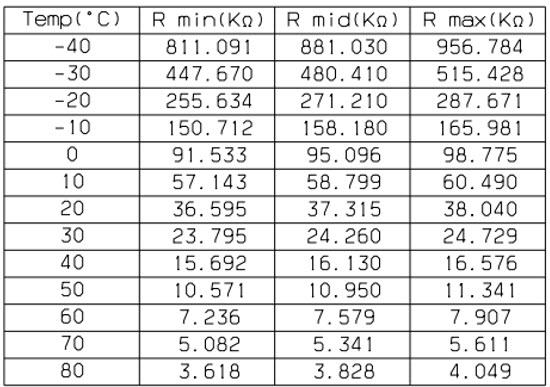
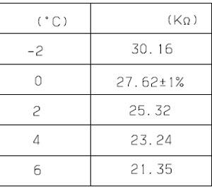
Appendix D: Coolant Heater Diagnosticslink
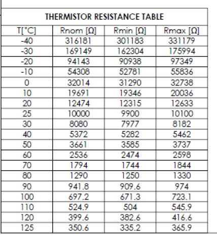
Heater element resistance: 37 Ohms
Temperature sensor resistance / temperature chart:
 |
|---|
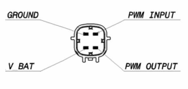
Appendix E: Coolant Pump Diagnosticslink
Minimum operating voltage = 8V
PWM Input (5V square wave)
Note
Pumps will default to 100% if there is no PWM input.
PWM Output (5V square wave)
 |
|---|
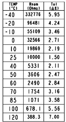
Appendix F: Coolant Temperature Sensor Diagnosticslink
Resistance / temperature chart:
 |
|---|
Appendix G: Ambient Air Temperature Sensor Diagnosticslink
Resistance / temperature chart:
 |
|---|
Appendix H: In-vehicle Temperature Sensor Diagnosticslink
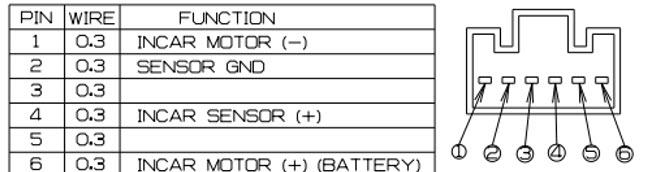 |
|---|
 |
|---|
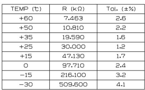
Appendix I: Evaporator Outlet Temperature Sensor Diagnosticslink
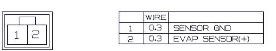 |
|---|
 |
|---|
Appendix J: Blower Motor Control Module Diagnosticslink
 |
|---|
Appendix K: Actuator Diagnosticslink
 |
|---|
 |
|---|
 |
|---|
 |
|---|
Appendix L: HVAC Unit Actuator Targetslink
 |
|---|
Appendix M: A/C Compressor Diagnosticslink
 |
|---|
 |
|---|
Appendix N: Condenser Fan Control Module Diagnosticslink
 |
|---|
Appendix O: Sensor Diagnosticslink
Suction Sensor Diagnostics
 |
|---|
 |
|---|
 |
|---|
Discharge Sensor Diagnostics
 |
|---|
|
|---|
 |
|---|