Side Mirrorslink
Last updated: October 20, 2023
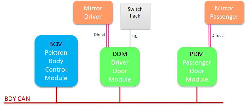
ECU and Communicationlink
For Model S, the body ECUs are made by an external supplier. The supplier also provides the firmware according to Tesla specifications.
The mirrors are controlled directly by door modules, which receive information from the window switch pack over LIN and from the body controller over CAN.
To synchronize both mirrors, commands are sent through the Driver Door Module (DDM) to the driver mirror, which then relays the command to the passenger mirror through the Passenger Door Module (PDM).
 |
|---|
Switch Packlink
 |
|---|
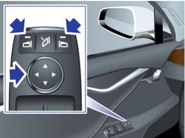
| Power fold and unfold both mirrors |
 |
|---|
| Select and Adjust tilt of left or right mirror |
Harness schematiclink
Tip
Harness schematics are subject to change. The specific schematic for the vehicle production date should always be referred to.
 |
|---|
Warning
Vehicles built before May 31st 2013 have a different pinout and may need a harness adaptor, see the service manual.
Optionslink
| MES Option Codes | ||
|---|---|---|
| X037 | Mirrors - Powerfold yes | Tech Package |
| BS00 | No Blind Spot Sensor Package | Not used |
Gatewaylink
| Name | Configuration | Values |
|---|---|---|
| Folding Mirrors | cfg_folding_mirrors | 0 (default), 1 (default) |
| Memory Mirrors | cfg_memorymirrors | 0 (default), 1 |
Folding and Unfoldinglink
 |
|---|
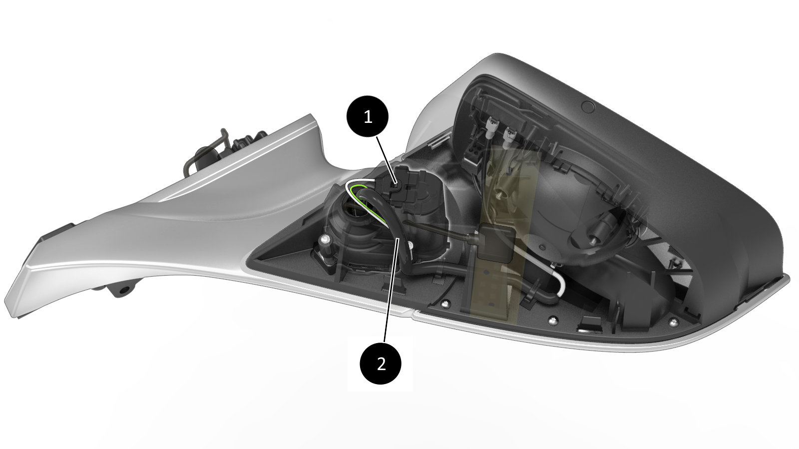
| 1. Powerfold motor 2. Powerfold connector |
| Powerfold Motor Installation |
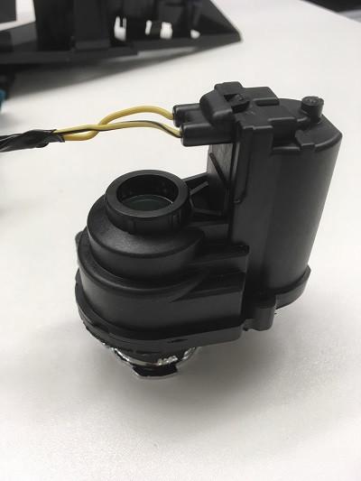 |
|---|
| Powerfold Motor |
Powerfold Motor Mirrors unfold when:
- The switch pack button is pressed and mirrors were previously folded.
- Speed is above 50kph/31mph.
- The mirrors automatically folded previously and one of the following
condition is true:
- The vehicle unlocks and 'Mirror Auto-Fold' setting is ON.
- The drive rail turns ON and firmware is not updating.
- The gear changes from Park to Drive, Neutral, or Reverse.
Mirrors fold when:
- The switch pack button is pressed and mirrors were previously unfolded and speed is below 50kph/31mph.
- The vehicle locks and Mirror Auto-Fold setting is ON.
- Summon state is ACTIVE.
In addition:
- Mirrors do not unfold automatically on unlock if they were previously folded manually using the switch pack button (i.e. to park in a tight space).
- The Driver Door Module (DDM) controls fold/unfold and sends commands to the PDM so mirrors do not get out of sync .
- MCU setting for automatic fold/unfold based on lock state: Controls > Settings > Vehicle > Mirror Auto-Fold [ON/OFF].
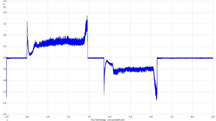
- Mirrors will fold or unfold until they reach their mechanical end or an obstacle, then the current will increase above a stall threshold and the movement will stop.
 |
|---|
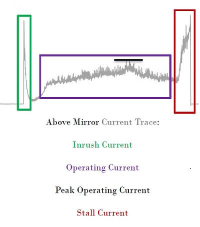 |
| Expected current profile |
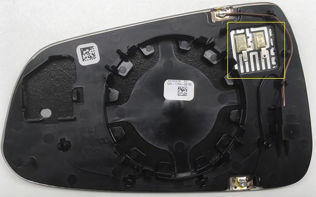
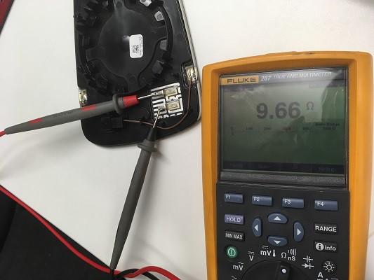
Heatinglink
 |
|---|
| Heater Connection |
The Mirror heater turns ON when pressing the MCU button for rear defrost, if the vehicle has memory mirrors and the Accessory (ACC) Rail is ON.
 |
|---|
| Expected resistance of the heating element: ~9.7 ohms |
No CAN logs signals are available.
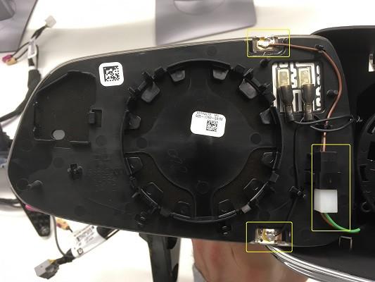
Dimminglink
 |
|---|
| Dimming Connections |
 |
|---|
| Light Sensor on the Back of the Central Rear View Mirror |
The mirror consists of two layers of glass with a layer of electrochromic gel in between. The gel changes color as the voltage changes. When voltage is applied, the gel darkens. When voltage is taken away, it lightens. With a light sensor placed in the rear view mirror, the amount of light coming from the back of the vehicle is measured, then communicated with the Gateway to make the decision to enable dimming or not. If dimming is enabled, a percentage value is sent to the rear view mirror and to both side mirrors (door modules) to activate dimming.
Tip
Usual dimming voltage: 1.2V (do not test with 12V!)
 |
|---|
| Dimming demonstration |
Auto-dimming is allowed if:
- Time is between sunrise - 15 minutes and sunset + 15 minutes (night).
- Vehicle is in Drive (disabled in Reverse).
To test the auto-dimming in Service during the day:
- Connect a laptop with Toolbox to the vehicle with a Diagnostic cable to turn on diagnostic mode (tdsMode).
- Shift to Drive.
- Cover the light sensor on the back of the central rear view mirror (to simulate darkness).
- Use a flashlight on the central rear view mirror, it should dim after 5s.
The central rear view mirror determines a dimming percentage based on the difference of light intensity between the front of the vehicle and the back and sends this over LIN to the Gateway.
The Gateway decides if auto-dimming is allowed based on the time of day, gear and diagnostic mode being active or not. If dimming is not allowed, dimming percentage = 0.
The Gateway then sends the final dimming percentage back to the central rear view mirror over LIN which dims accordingly and sends an analog signal to both door modules to activate side mirrors dimming.
No CAN logs signals are available.
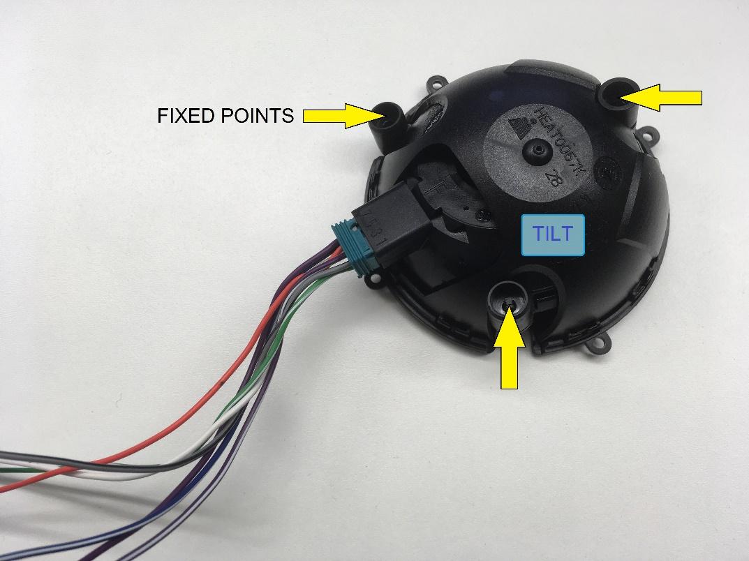
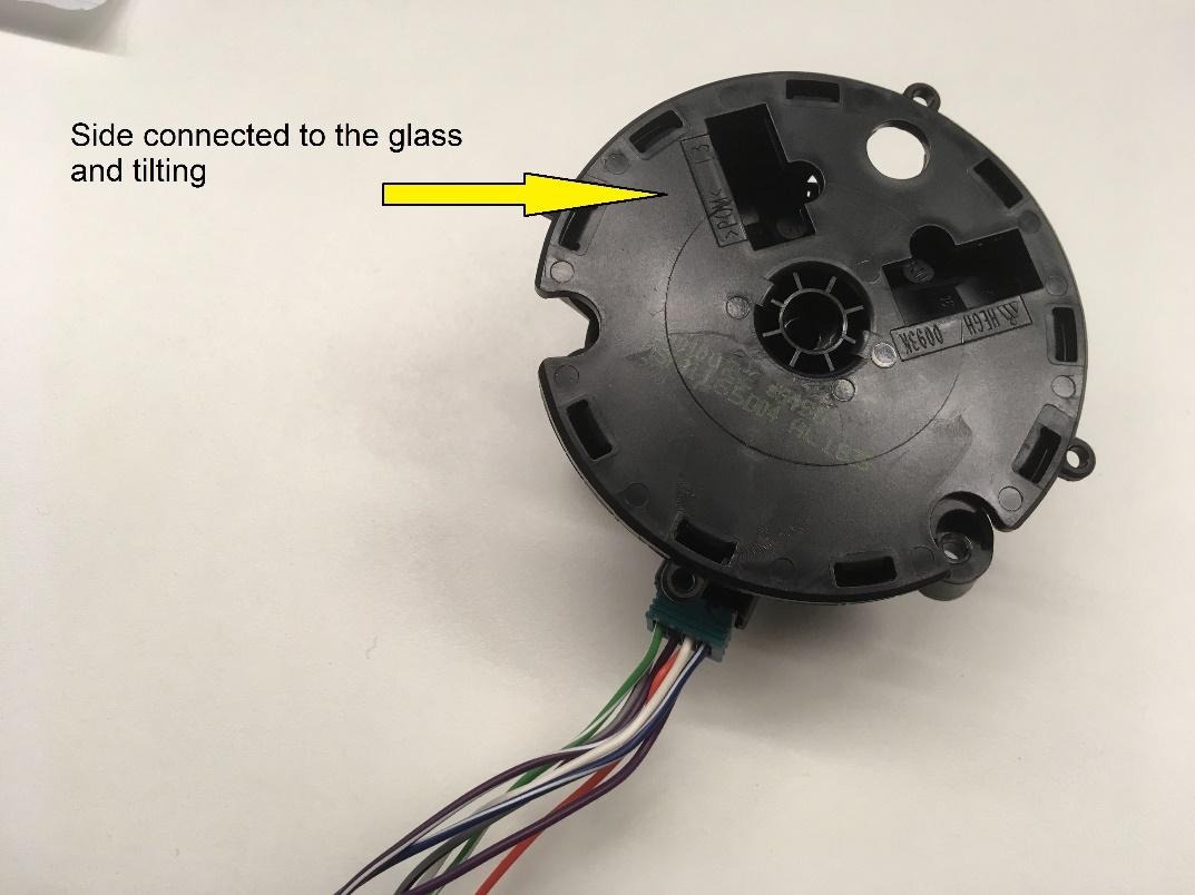
Tiltlink
 |
|---|
 |
|---|
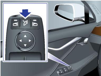
Controlling the mirrorslink
- A mirror is selected by pressing the corresponding button on the driver's switch pack.
- The mirror glass tilts up, down, left, or right using the corresponding arrows.
- When changing the tilt of the passenger mirror, the Driver Door Module (DDM) gets the request and passes it to the Passenger Door Module (PDM) over CAN (the switch pack is connected to the Driver Door Module (DDM).
Mirror Memorylink
When the driver or passenger mirror has been tilted on either the X or Y axis, the Gateway (GTW) is alerted and offers to save the new setting to the selected driver profile. The tilt position is saved in the Driver Door Module (DDM) and Passenger Door Module (PDM).
When a driver profile is selected, the mirror tilt position is recalled by the GTW requesting a recall position over CAN that is sent to the door module.
If a Driver Door Module (DDM) or Passenger Door Module (PDM) is replaced, the stored tilt setting for the corresponding mirror is lost.
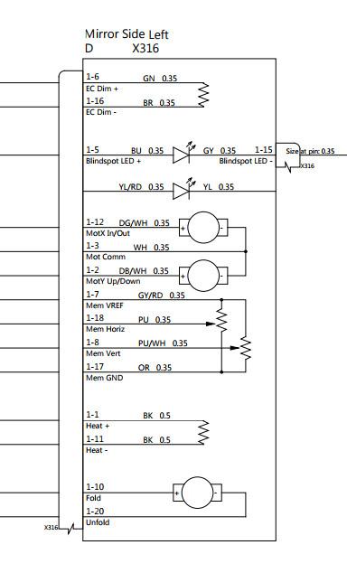
In order to tilt the mirrors, two small DC motors located behind each mirror glass are used. Through a reduction gearbox the motors turn two outer gears on the vertical and horizontal axes, which cause the assembly attached to the glass to tilt respectively to the fixed bracket shell.
Two sensors feedback the current X and Y axis position as a voltage measurement through an Analog to Digital converter (using a 5V reference) to the door module.
AutoTiltlink
Autotilt gets enabled on the MCU: Controls > Settings > Vehicle > Mirror Auto-Tilt. When Reverse is selected, both mirrors will tilt down by a standard offset. When Reverse is selected, it is also possible to select a bespoke position and save it to the current driver profile so that next time Reverse is selected, the mirrors will tilt to this new position instead of using the standard offset.
No CAN logs signals are available.
Antennaslink
Each individual side mirror contains a cellular antenna. The right mirror contains the primary cellular antenna and also the 2.4GHz WiFi antenna. The left mirror contains only the secondary cellular antenna.
 |
|---|
| Left Mirror |
 |
|---|
| Right Mirror |