Drive Unitslink
Last updated: October 20, 2023
Overviewlink
General Informationlink
Danger
Obey all high voltage safety requirements anytime the drive unit is part of a vehicle repair. The drive unit contains 550uF of internal capacitance, enough to be lethal if the internal discharge functions are not working properly. Always use a multimeter to confirm that dangerous voltage is not present on the DC input connector of the drive inverter.
The drive unit contains a motor, gearbox, and drive inverter. The component parts of the assembly are highly integrated to reduce system complexity and improve reliability.
The drive unit takes electrical energy from the battery and converts it into mechanical torque, which is transferred to the wheels.
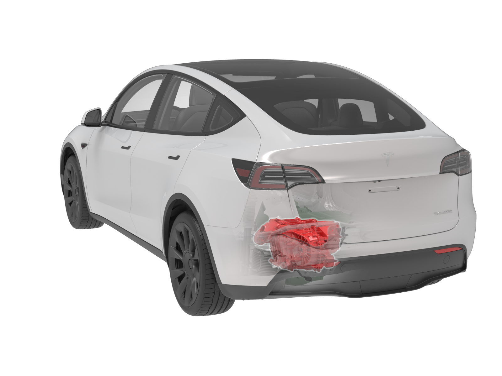
The rear drive unit is located between the rear wheels, underneath the trunk. The half-shafts connect the wheels to the drive unit. The rear drive unit assembly is mounted to the rear sub-frame with three mounts: (1) a rear mount, integrated into the gearbox case, (2) a right mount, integrated into the motor housing, and (3) a left mount, bolted on the gearbox housing above the drive inverter.
 |
|---|
| Rear Drive Unit - Location |
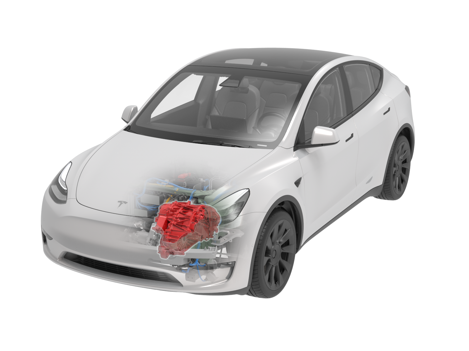
The front drive unit assembly is mounted to the front subframe with three mounts: (1) a front mount, integrated into the gearbox case, and connected via the front subframe (2) a right mount, integrated into the motor housing and (3) a left mount, bolted on the gearbox housing above the drive inverter.
 |
|---|
| Front Drive Unit - Location |
For AWD vehicle configuration, each drive unit gives motion to the wheels in the respective axle. The two drive units are not mechanically connected to each other.
The drive units connect to the vehicle in six ways:
- High Voltage (HV) Harness
- Low Voltage (LV) Harness
- Half-shafts
- Coolant Hoses
- Mounts (x3)
- Ground strap
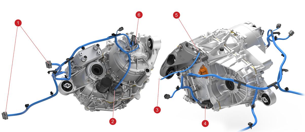
The drive unit(s) are mechanically and electrically connected to the vehicle.
 |
|---|
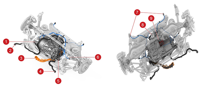
| 1. Right Drive Unit Mount to Subframe 2. Rear Subframe Coolant Outlet 3. HV Battery Connector for Rear drive unit 4. Rear Subframe Coolant Inlet 5. Left Drive Unit Mount to Subframe 6. Drive Unit Chassis ground point 7. Rear Subframe Low Voltage Harness Connectors (to Body) 8. Rear Drive Unit Mount to Subframe 9. Drive Unit Torque Output |
| Rear Drive Unit - Mounting and Connections |
 |
|---|
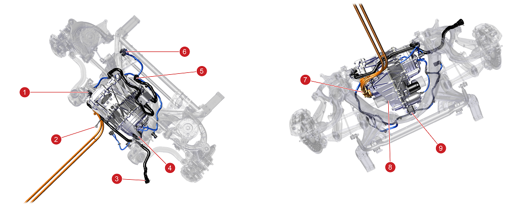
| 1. Left Drive Unit Mount to Subframe 2. Drive Unit Chassis ground point 3. Front Subframe Coolant Inlet 4. Right Drive Unit Mount to Subframe 5. Front Subframe Coolant Outlet 6. Front Subframe Low Voltage Harness Connector 7. HV Connector to Front Drive Unit 8. Drive Unit Torque Output 9. Front Drive Unit Mount to Subframe |
| Front Drive Unit - Mounting and Connections |
Drive Unit Mountslink
 |
|---|
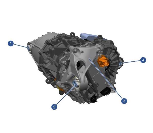
| 1. Right Mount Bushing 2. Left Mount Bushing 3. Left Mount 4. Rear Mount Bushing |
| Rear Drive Unit Mounts |
Note
Rear drive unit shown, front drive unit is similar.
Coolant Hose Connectionslink
 |
|---|
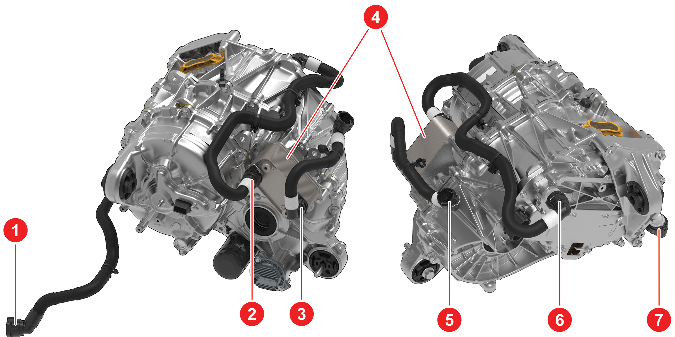
| 1. Rear Subframe Coolant Inlet 2. Heat Exchanger Inlet 3. Heat Exchanger Outlet 4. Heat exchanger 5. Front Subframe Coolant Outlet 6. Drive Inverter Coolant Outlet 7. Drive Inverter Coolant Inlet |
| Front Drive Unit Coolant Hose Connections |
 |
|---|
| 1. Drive Inverter Coolant Outlet 2. Rear Subframe Coolant Inlet 3. Drive Inverter Coolant Inlet 4. Heat Exchanger 5. Heat Exchanger Inlet 6. Rear Subframe Coolant Outlet 7. Heat Exchanger Outlet |
| Rear Drive Unit Coolant Hose Connections |
High and Low Voltage Connectionslink
 |
|---|
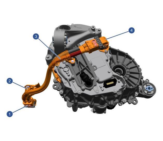
| 1. HV Battery Connector 2. Drive Inverter DC Voltage Bracket 3. Drive Inverter DC Voltage Bracket 4. Drive Unit Connector |
| High Voltage Connections |
Communication between the drive unit and the rest of the systems is slightly different depending on the drive unit (master/slave), but the interface is exactly the same.
The rear drive unit (Master) takes direct input from the accelerator pedal and the brakes over CAN in order to define the operating condition. The front drive unit (Slave) takes the command for the required operation condition from the rear-master drive unit via CAN.
 |
|---|
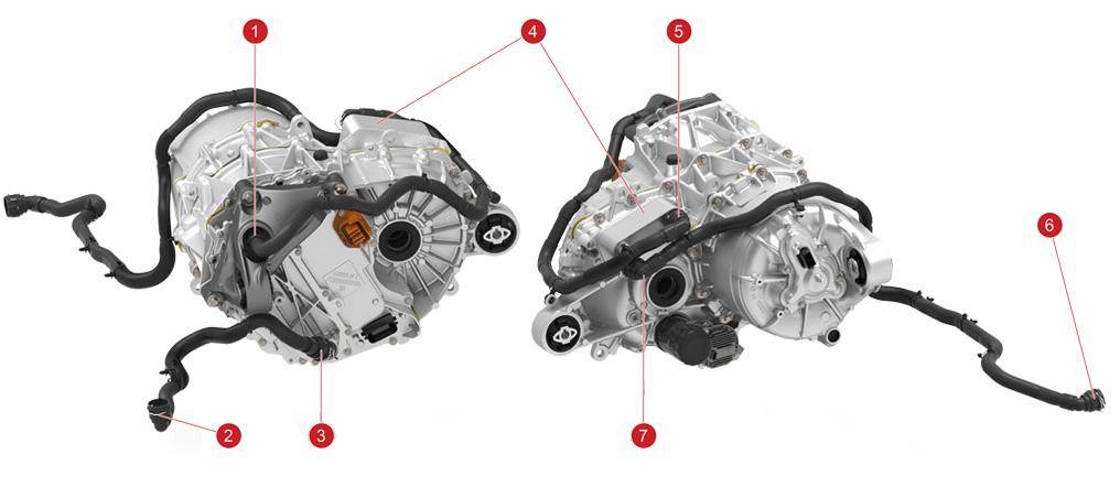
| 1. Rear Subframe Harness Connectors to Body 2. Oil Pump Connector 3. Ground to Chassis 4. Drive Inverter Logic Connector 5. Ground Attachment 6. Resolver |
| Rear Drive Unit Low Voltage Harness Connections |
Note
Rear drive unit shown, front drive unit identical
Drive Inverterlink
Overviewlink
The drive inverter converts the Direct Current (DC) from the battery pack into three Alternating Current (AC) phases in the Stator. The current waveforms are 120° out of phase with each other and create a rotating magnetic field in the stator.
For an induction motor, the stator field induces current in the rotor. The induced rotor current creates a second magnetic field that opposes the stator field, producing motor torque. For a permanent magnet motor, the permanent magnets inside the motor have a permanent magnetic field. The interaction of this permanent field with the stator's rotating magnetic field, produces a motor torque. The speed of the motor depends on the frequency of the AC supplied by the drive inverter. The torque of the motor depends on the amplitude of the AC. In a permanent magnet motor, the torque will also depend on the electrical angle difference between stator and permanent magnet magnetic fields.
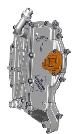 |
|---|
| Front Drive Inverter |
The Drive Inverter translates driver commands from the gear selector and accelerator into alternating currents that are applied to the motor to generate the correct speed, torque, and direction of rotation to move the vehicle. The Drive Inverter is a bi-directional system, converting battery current to motor current – with current flowing in either direction and output torque in either direction. Regenerative braking is achieved using the drive inverter to produce negative torque and corresponding current flow from the motor to the battery. Regenerative braking is only allowed when the stability control and ABS systems are active. Traction control is implemented in the stability control system in Model Y, with torque limiting commands sent to the Drive Inverter when traction is reduced.
Waste Heat Modelink
Model Y does not have an external high voltage coolant heater. The battery heating is acheived with the use of the heat pump. Additional to the heat pump, the drive units contribute in heating up the HV battery by providing more heat to support the heat pump or by taking over the battery heating when heat pump is faulty. Both front and rear Model Y drive units contribute to waste heat mode. Under cold soak conditions, the Front Controller (VCFRONT) sends a request to the drive inverter(s) to produce the necessary power that is required to heat the coolant and therefore HV battery cells. Current is used to heat the stator, without changing the torque/speed output, which will heat the transmission fluid being pumped and heat transferred to the coolant being pumped thought the heat exchanger.
- If the vehicle is being driven, the motor control strategy changes to produce excess powertrain losses in order to provide heat to the HV battery.
- In the case that the vehicle is parked in the cold and the HV battery needs to be heated up, the drive inverter provides the appropriate current to the motor to produce heat with zero torque/speed change.
Regenerative Brakinglink
Regeneration operates on the principle that the electric motor can also act as an electrical generator. This places a load on the motor, which in turn provides an additional braking effect.
The amount of regen torque generated is dependent on vehicle speed, battery state of charge, accelerator pedal position and user-specified regen settings. The pedal provides maximum available regen torque when fully released, then proportionally less as the pedal is depressed. The motor delivers zero regen torque when the accelerator pedal reaches its neutral torque position, which moves depending on driving and vehicle conditions.
Note
A failure of the antilock braking system (ABS) or electronic stability program (ESP) system disables regenerative braking. A notification is displayed on the touchscreen. Regen may also be reduced or disabled when the tires may be traction limited, such as in cold weather or during traction control events. Regen will be limited or disabled if battery state of charge (SOC) is too high.
The Drive Inverter converts this torque command into the appropriate 3-phase voltage and current waveforms to produce the commanded torque in the motor in the most efficient way. The torque command can be positive or negative. When the torque is used to slow the vehicle, energy is returned to the HV Battery to store for later use.
The maximum regeneration braking profiles take speed and corresponding drag into account to aim for a target total vehicle deceleration rate, not an energy recovery target. Regeneration braking profiles are tailored to everyday driving conditions, and typically provide higher deceleration rates at lower speeds.
Temperature Sensorslink
The Model Y drive inverter has five temperature sensors: two on heatsink between phases, one on the heatsink near the fluid port closest to the logic connector, one on the front of the PCBA near the DSP, and one on the back of the PCBA behind the active discharge resistors. Other temperatures such as the DC link capacitor and phase out busbar are calculated in real time by the main core of the DSP. If the inverter detects any of these temperatures exceeding expected values (if coolant flow is lost for example) it will limit its own power output to an operational level.
Gearboxlink
Overviewlink
The drive unit features a single speed gear reduction gearbox, located between the Motor and the Drive Inverter. The Gearbox uses a layshaft arrangement with two stage gear reduction.
There is no mechanical linkage between the gear selector and the gearbox. The gearbox gear set is in constant mesh. The gearbox has no mechanical neutral or reverse gear, and no parking pawl. Reverse drive is achieved by reversing the polarity of motor torque. Neutral is achieved by de-energizing the front motor or appropriately controlling the permanent magnet motor to produce zero torque.
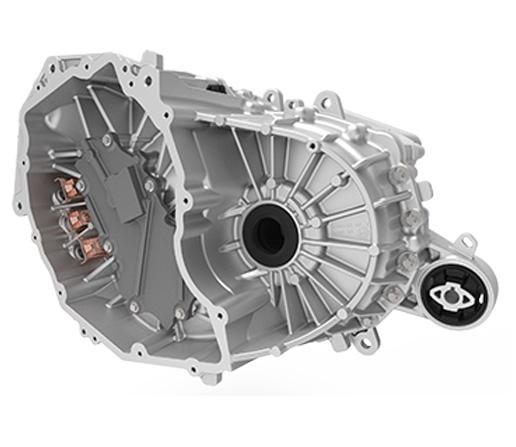 |
|---|
| Rear Gearbox, Left-hand Side |
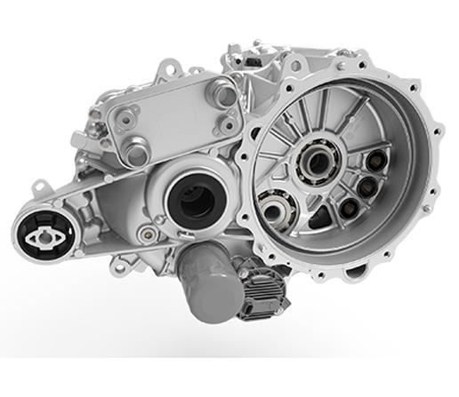 |
|---|
| Rear Gearbox, Right-hand Side |
Description and Operationlink
Both front and rear drive units have a 9:1 gear ratio and two gear stages. The input gear, the intermediate gear, the output gear and their bearings are the same. However, the windage tray and the gearbox cases are different. Every shaft is preloaded with the use of shims, to maximize the bearing life and reduce the movement of the shafts.
Note
The input and intermediate shims will be eliminated in 20Q3.
Output Gear (Differential)link
The open differential is a conventional design with the differential carrier bolted to the final drive ring gear. The housing supports the differential pin, side gears, and pinion gears. The differential assembly is supported in the gearbox assembly using deep groove ball bearings.
The differential allows the road wheels to turn at different speeds while providing an equal amount of torque. The integral spline on the drive shaft meshes with the side gear on the differential assembly. When the drive shaft rotates and the wheels are traveling at the same speed, torque is applied to the complete assembly; the pinion gear does not rotate. Torque is transmitted to the road wheels through the drive shafts. During cornering, the inner wheel travels a shorter distance at a lower speed. This results in the pinion gears rotating about the outer wheel side gear, therefore increasing the speed of the outer wheel.
Oil Pumplink
The drive inverter controls the electric oil pump, with feedback of motor electrical load and Transmission Fluid temperature. The operating temperature range is -40°C to 140°C. The electric oil pump is controlled based on many input conditions that allow improved drive unit efficiency, improved thermal system performance, and enables waste heat mode. This is achieved by transferring energy in the form of heat, from the stator to the heat exchanger, where coolant is heated. The oil pump is a Tesla in-house component used to gain full control of Electronic (ECU) hardware and firmware. The oil temperature is detected and reported by the oil pump thermistor. The temperature is allowed to vary within a given range. When the temperature exceed the design limits, an alert signal will be triggered and the performance of the drive unit is limited. If there is insufficient flow of oil in the drive unit, the same outcome is to be expected.
Motorslink
Overviewlink
There are different types of motors to serve different purposes, but all of them follow the same principles. The torque in every electric motor is created is by two magnetic fields that interact to each other, causing forces that rotate the rotor. Depending on the way that the necessary magnetic fields are created, the motors are divided in different categories. The Model Y front drive unit is an asynchronous induction motor and rear drive unit is a synchronous permanent magnet motor (PM). Model Y has this exact configuration of motors because it is the most efficient configuration. The vehicle only needs one motor most of the time, which is the rear PM drive unit. The front drive unit is therefore often idling. The induction motor drive unit is therefore most suitable as a front drive unit as it is lighter, lower cost and has lower losses when unpowered.
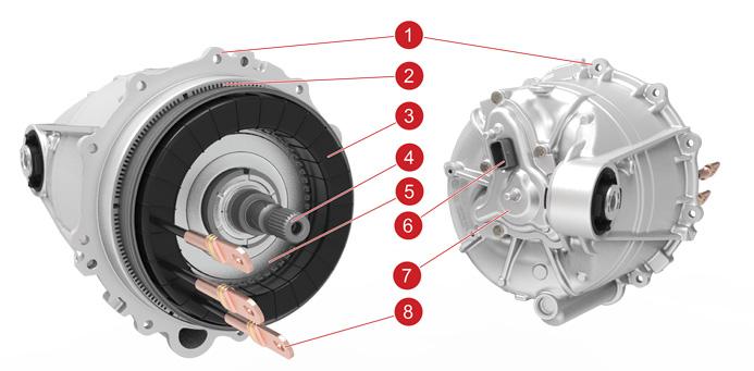
Permanent Magnet Motorlink
In permanent magnet motors, the magnets always have an established magnetic field in the rotor. When the stator windings are fed with 3- phase AC current, a rotating magnetic field is also established in the stator. If the stator was fed by DC current the magnets of the neighboring rotor magnetic pole would be attracted, causing the rotor to move until the magnets are aligned with the peak of the stator magnetic field. However, in this case, the rotor would stop moving after reaching this position. When applying AC current, the magnets of the rotor are “chasing” continuously the peak of the rotating magnetic field of the stator. The torque in the permanent magnet motors varies by controlling the amplitude of the stator current and the internal angle between the magnets and stator magnetic fields. The 2 fields rotate synchronously (there is no frequency difference between them) and this is the reason that this type of motors are also called Synchronous motors. If the current supply of the stator suddenly stops, there is still remaining magnetic field in the motor because of the existence of the magnets. This might lead to unexpected behavior of the motor during a fault case. The motor controller is responsible in detecting any abnormal operation and eliminate the impact that has to the system.
 |
|---|
| 1. Stator Housing 2. Stator Steel 3. Stator Windings 4. Rotor Shaft 5. Rotor Balance Ring 6. Resolver 7. Resolver Cover 8. 3-Phase Lugs |
| Permanent Magnet Motor |
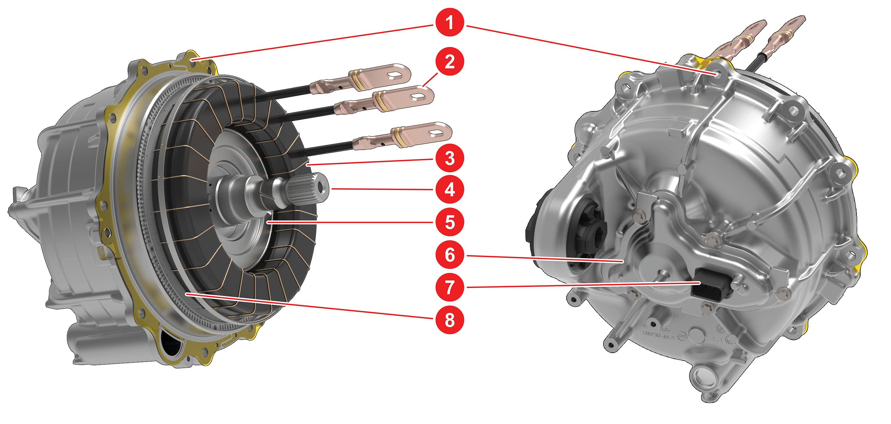
Induction Motorlink
An induction motor (3-phase induction motor or asynchronous motor) is an AC electric motor in which the electric current in the rotor needed to produce torque is obtained by electromagnetic induction from the magnetic field of the stator winding.
In an induction motor, the AC power supplied to the stator creates a magnetic field that rotates in synchronicity with the AC oscillations. The motor's rotor rotates at a somewhat slower speed than the stator field. The induction motor stator's magnetic field is therefore changing or rotating relative to the rotor. This induces an opposing current in the induction motor's rotor, in effect the motor's secondary winding, when the latter is short-circuited or closed through an external impedance. The rotating magnetic flux induces currents in the windings of the rotor. The torque can vary in induction motor by changing the amplitude of the stator AC current and the slip frequency. These 2 parameters are selected and commanded by the motor control, which is getting feedback from the accelerator pedal, the brakes, motor speed and the position of the rotor. When current stops flowing into the stator windings, the magnetic field collapses. The motor will continue spinning freely until stopped by mechanical losses, either internal or external (brakes, road grade, etc.).
 |
|---|
| 1. Stator Housing 2. 3-Phase Lugs 3. Stator Windings 4. Rotor Shaft 5. Cast Aluminum Rotor 6. Resolver Cover 7. Resolver Connector 8. Stator Steel |
| Induction Motor |
Motor Speed Sensor (Resolver)link
All Model S/Model X drive units use an encoder to sense the speed of the rotor. Model 3 and Model Y drive units use a different sensor known as a resolver. Unlike the encoders which are speed sensors, the resolver directly measures the angle of the rotor. Speed measurements are derived from position measurements made over time. A resolver works similarly to a transformer where the amount of coupling between primary and secondary coils is determined by the angle of the resolver rotor (press fit onto the motor rotor) relative to the resolver stator (in the resolver cover assembly). The resolver stator is connected to the inverter control board via an external cable, making the entire component more service friendly.
Stator Temperature Estimationlink
In Model Y drive unit there is no stator thermistor. The stator temperature is estimated using the oil pressure and temperature. Oil pressure and oil flow alerts can be expected when the stator is not operating under its nominal temperature range.