Brake Systemlink
Last updated: October 20, 2023
Overviewlink
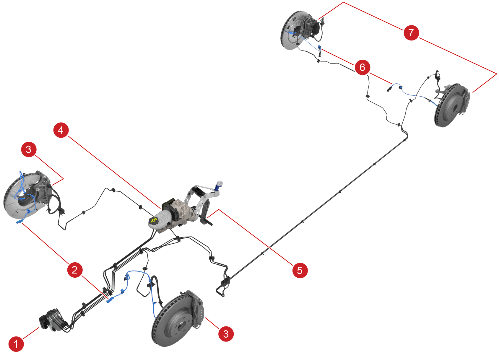
The brake system installed on the Model S is a hydraulic based brake system, consisting of 4 disc brake calipers and Electronic Stability Program (ESP).
The front brakes consist of a one piece vented rotor and fixed 4 piston caliper.
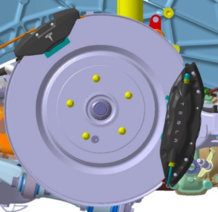
The rear brakes consist of a one piece vented rotor and depending on configuration either have a fixed 4 piston caliper and a separately mounted single piston fixed caliper for the EPB (Brembo) or a single piston floating caliper (Mando) with an integrated Electronic Park Brake (EPB).
Note
For EPB operation, see Electric Park Brake Theory of Operation.
There are three types of braking systems for the Model S:
- Brembo separate EPB without iBooster
- Brembo separate EPB with iBooster
- Mando integrated Caliper/EPB with iBooster
 |
|---|
| Brembo Rear Caliper and Standalone_EPB |
 |
|---|
| Mando integrated Rear Caliper/EPB |
 |
|---|
| 1. ESP Hydraulic Unit 2. Front Wheel Speed Sensors 3. Front Brake Calipers 4. Brake Reservoir and Booster 5. Brake Pedal 6. Rear Wheel Speed Sensors 7. Rear Brake Calipers Not shown in Diagram - Steering Column Control Module (SCCM) - Yaw Sensor - Vacuum Pump, no iBooster |
Warning

RED brake indicator is displayed at any time other than initial start donates a brake system fault or low brake fluid level has been detected
Componentslink
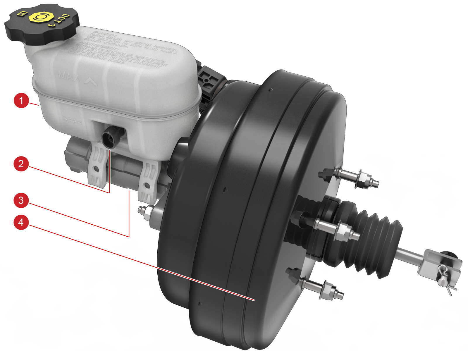
Brake Boosterlink
The brake booster assembly is of a standard, suspended vacuum, single diaphragm type. The circular housing contains diaphragms, a driving piston, a control valve assembly, input and output push rods and a non-serviceable filter. The input push rod is connected to the brake pedal and passes through the driving piston to the control valve assembly. The output push rod locates in the primary piston of the master cylinder. A port in the front face of the booster housing is connected to a vacuum line from the vacuum pump via an elbow joint. A vacuum sensor is incorporated into the elbow joint.
The brake booster assembly provides assistance to reduce the pedal effort when braking. If the brake booster assembly faults, the hydraulic system still functions but will require greater brake pedal effort due to the lack of vacuum assistance.
The booster only operates when a vacuum is available. The vacuum pump produces an approximate vacuum of -10 psi (-0.7 bar) which produces approximately eleven times the force at the output push rod than was exerted on the input push rod by the brake pedal.
In the event of booster malfunction, the input push rod can be pushed forward into contact with the output push rod. This provides a direct mechanical link between the brake pedal and the master cylinder
Warning
Only Tesla-approved brake fluid is permitted in the brake system. The use of any other unapproved fluid may result in performance degradation or malfunction. Do not use fluid from unsealed containers, as it might have absorbed moisture from the atmosphere.
 |
|---|
| 1. Brake Reservoir 2. Brake Fluid Level Switch 3. Brake Master Cylinder 4. Brake Servo |
| Brake Booster - Vacuum Assist |
Brake fluid Reservoirlink
The brake fluid reservoir is mounted is directly on the master cylinder. The translucent plastic brake fluid reservoir allows the brake fluid level to be checked using the level markings on the outer surface it also incorporates a level sensor.
Brake Master Cylinderlink
The brake master cylinder is a non-serviceable conventional tandem type unit mounted onto the front face of the booster. Two internal pistons separate the independent diagonal brake circuits. Two larger diameter pipes transfer brake fluid from the master cylinder to the ESP Control Unit. When the brake pedal is pressed, the movement of the master cylinder piston produces hydraulic pressure which passes through the brake pipes to the ESP unit and onto the calipers. The diagonally split braking circuit ensures that braking is still available to one circuit albeit at a reduced level with increased foot pedal travel if one circuit of the system suffers hydraulic malfunction.
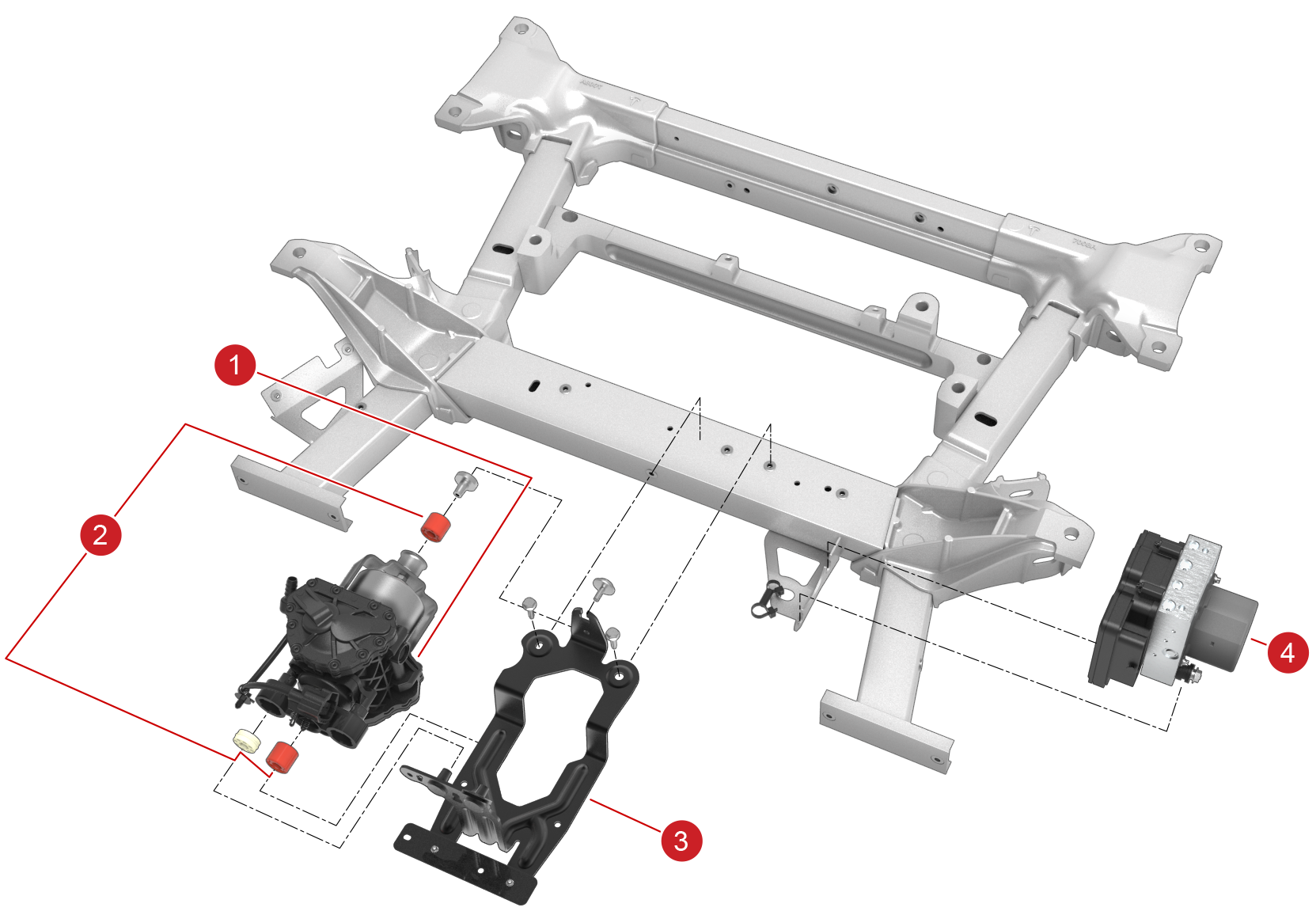
Vacuum Pumplink
 |
|---|
| 1. Vacuum Pump 2. NVH Rubber Mounts 3. Pump Bracket 4. ESP Control Unit |
| Vacuum Pump Mount |
The pump assembly is non-serviceable unit encased in a hard plastic outer casing and mounted to a bracket via three rubber NVH isolators. The complete assembly and bracket is then bolted to the front sub-frame cross-member.
The pump consists of an electric motor which drives two vertically opposed pistons and diaphragms to provide improved balance and reduced vibration. Both pumping chambers are linked by a single tube and air is drawn from the booster through an aluminum reinforced hose which prevents collapse. Non-return valves are fitted to each chamber to prevent leakage. The pumped air is exhausted through a machined exit port via a non-serviceable foam filter.
The motor is controlled via Relay K14 located in the front fuse-box.The ESP ECU uses a vacuum sensor installed in the front shell of the brake booster to determine the current vacuum level in the system. The vacuum sensor switches power off if a pre-determined level of vacuum is exceeded; the pressure switch starts the pump if vacuum is insufficient.
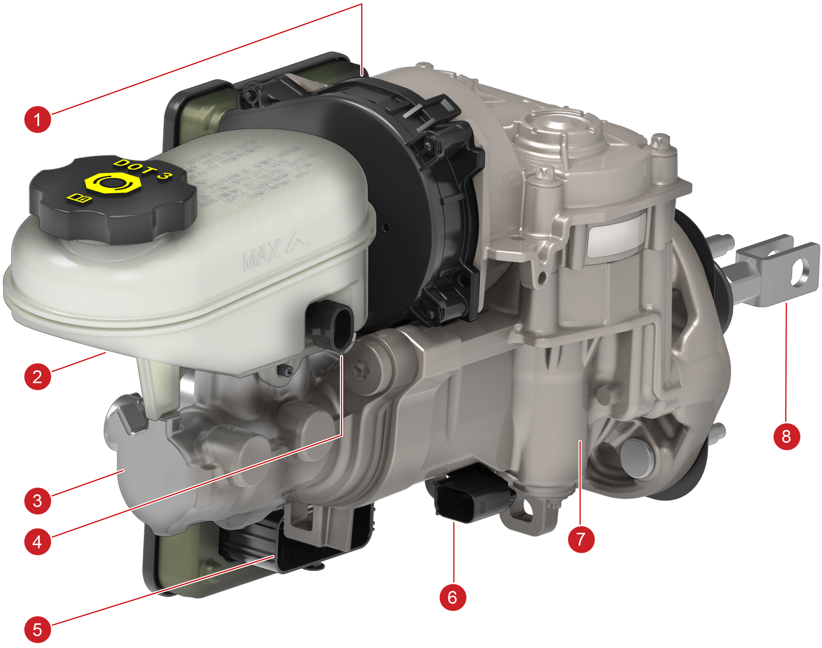
Brake iBoosterlink
 |
|---|
| 1. iBooster ECU 2. Brake Fluid Reservoir 3. Tandem Master Cylinder (TMC) 4. Brake Fluid Level Sensor 5. iBooster ECU Connectors 6. iBooster Pedal Travel Sensor 7. iBooster Gear Housing 8. Input Rod |
| Brake Booster - Electromechanical |
The 1st generation electromechanical brake iBooster is a vacuum-free electromechanical actuated system which is an integral part of the brake system. The iBooster detects the driver’s brake demand by an integrated pedal travel sensor and this information is sent to the integrated control unit. The control unit operates the electric motor, while a gear unit converts the motor torque into the necessary longitudinal boost force. The force supplied by the booster and the driver is converted into hydraulic pressure in a conventional master brake cylinder. This is distributed into the rest of the hydraulic system via the ESP unit.
In the case of a vehicle request from the DAS system, the iBooster control unit converts the mechanical torque request into a necessary longitudinal boost force which acts directly on the master cylinder to apply brake force to the master-cylinder independent of the driver to develop the demanded pressure.
If the iBooster suffers an irrecoverable fault, such as disruption of supply-power, the driver can still brake. This brake energy is transmitted mechanically through the booster to the tandem master cylinder. This master cylinder is responsible for transmitting fluid volume throughout the downstream hydraulic brake system, and sealing against the resultant increasing hydraulic pressure. This is the farthest upstream element of the “wet” hydraulic system. The master cylinder consists of two floating hydraulic pistons in series. There are two hydraulic inlets, one for each piston, from the fluid reservoir, and two hydraulic outputs, one for each piston, routed to the ESP hydraulic control unit. This unit is bolted directly to the iBooster housing.
The ESP system is able to detect reduced brake force due to malfunction and will generate additional brake force to aid the driver by using its own hydraulic pump (normally used for stability and traction control events). The brake force is metered proportional to the measured upstream hydraulic pressure from the tandem master cylinder, to allow reasonable modulation of brake force by the driver. During this time, pumping noise and pedal pulsations will be felt through the brake pedal by the driver. This is the intended back-up operating mode, and allows a much greater vehicle deceleration to be achieved than by the driver’s muscular energy alone. This function is called Hydraulic Brake Boost (HBB).
Warning
Only Tesla-approved brake fluid is permitted in the brake system. The use of any other unapproved fluid may result in performance degradation or malfunction. Do not use fluid from unsealed containers, as it might have absorbed moisture from the atmosphere.
Note
- Except the Brake Fluid Level Sensor, all parts are non-serviceable.
- No 3rd-party modification of this component is permissible.
- Foreign magnetic fields must be kept away from the ECU at all times.
Brake Fluid Reservoirlink
The brake fluid reservoir, mounted on top of the TMC, is a specially-formed translucent plastic reservoir which allows the brake fluid level to be checked using the level markings on the outer surface. The brake fluid reservoir houses a fluid level indicator which will set a warning light on the Touch Screen and will log an Alert in log data if the brake fluid level is too low.
Booster Assemblylink
The booster assembly itself can be broken down to 3 key functional areas to aid service and troubleshooting discussions:
Powerpacklink
The powerpack is the ECU and motor housing. All of the electronic controls are located within the black plastic ECU housing. The housing is permanently attached to the booster motor housing, and is non-serviceable. The 12V-brushless DC motor is located in the cylindrical steel housing fastened to the booster assembly. Motor rotation is measured using a rotational hall-effect sensor. There is one electrical interface on the ECU housing to connect to the vehicle.
Gear Housinglink
The primary booster mechanical components are located inside the steel housing. The internal components are physically separate from the master cylinder and brake fluid volume, as well as the external environment. This is a clean zone – no foreign contaminants, such as dirt, liquid, or any solvents or lubricants are permitted to enter the housing. Translation of the motor shaft rotation to linear motion is done by a gear-set inside this housing. A mechanical device to enable the driver to modulate brake force is packaged with the transmission. Located in the gear housing is the Differential Travel Sensor (DTS). The steel gear housing helps shield the DTS from magnetic interference.
Input Rodlink
The input tie-rod is the mechanical link between the brake pedal arm and the booster internal mechanism. It is connected to the pedal arm by a clevis and pin, and enters the booster housing through a rubber bellows, this is extended through the entire booster via another tie-rod to rigidly couple with the Tandem Master Cylinder. The input tie-rod is very sensitive to all mechanical loading while not mounted.
Warning
Extreme care should be taken when handling the booster while not fully-assembled in the vehicle, to avoid permanently damaging the booster mechanism. See the Service Manual for installation notes and care points.
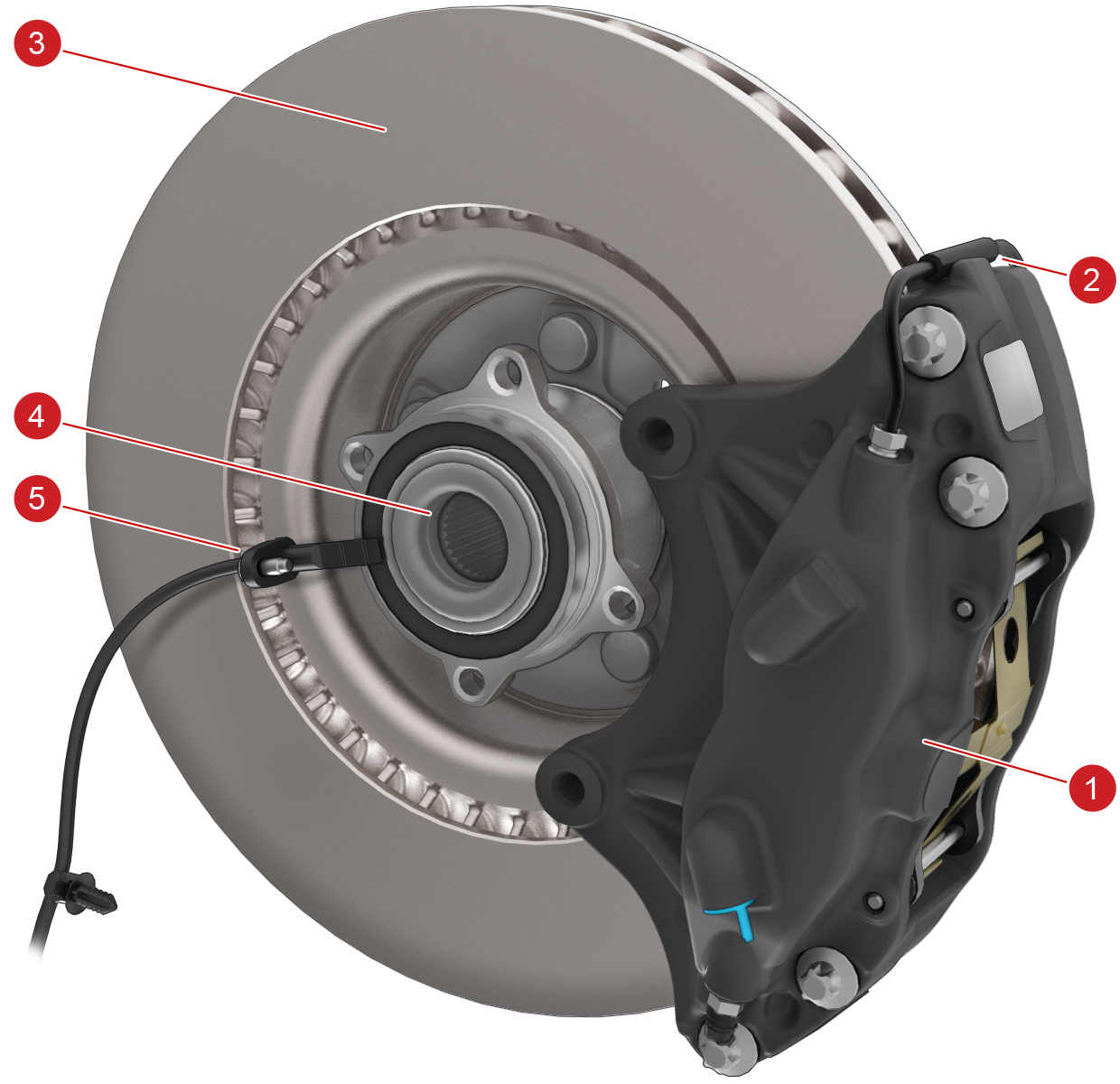
Front Brake Caliperslink
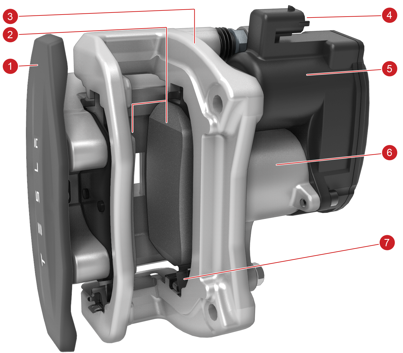
The front brake system uses a mono-block anodized aluminum four-piston design fixed caliper with dual bleed nipples. The Brake Fluid Link Pipe is the only serviceable component of the main caliper body. Depending on specification the main body is either Red or Black
 |
|---|
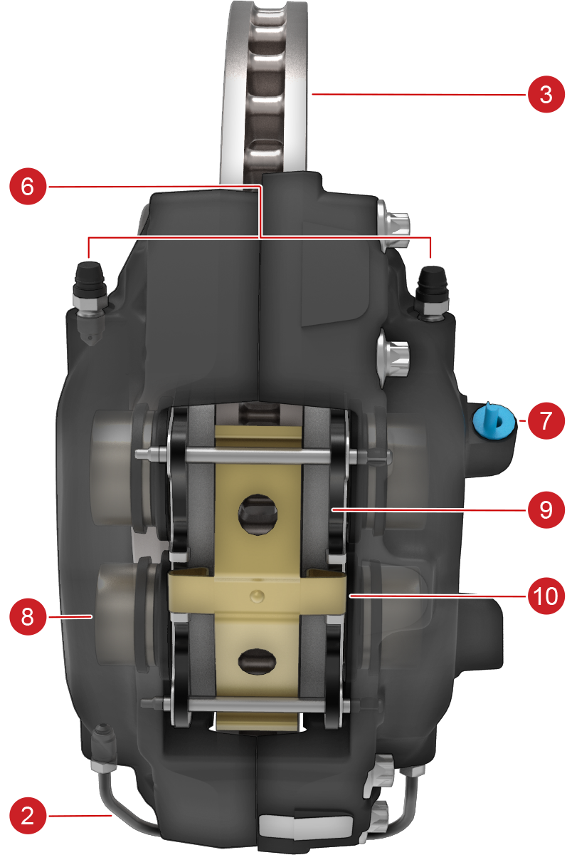 |
| 1. Brake Caliper 2. Brake Fluid Link Pipe 3. Brake Rotor 4. Wheel Bearing (incorporates Sensor Ring) 5. Wheel Speed Sensor 6. Brake Fluid Bleed Nipples (x2) 7. Brake Fluid Flexible Pipe Connection 8. Brake Piston (x4) 9. Brake Pads 10. Brake Pad Anti-Rattle Shim |
| Front Caliper Diagram |
Rear Brake Caliperslink
Brembo Rear Brake Caliperslink
Rear brake caliper mono-block anodized aluminum four-piston design fixed caliper with dual bleed nipples. The brake fluid link pipe is the only serviceable component of the main caliper body. Depending on specification, the main caliper body is either Red or Black.
|
|---|
See Front Brake Caliper for component break-down.
Note
For information on the separate dedicated EPB single piston caliper, see Electric Park Brake Theory of Operation.
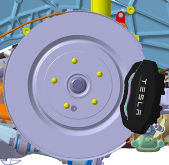
Mando Rear Brake Caliperslink
|
|---|
 |
|---|
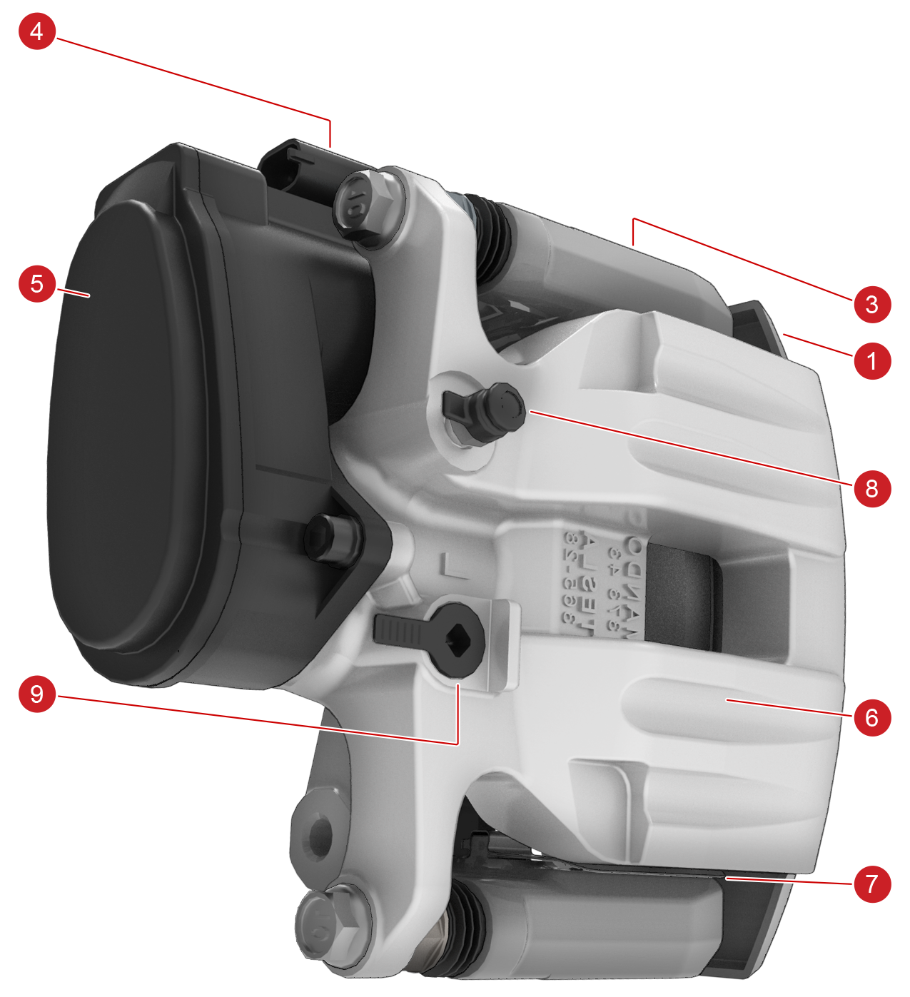 |
| 1. Caliper Outer Cover 2.Brake Pads 3.Solid Mount Brake Caliper Bracket 4.EPB Electrical Connector 5.EPB Motor Housing 6.Single Piston Sliding Caliper Body 7.Brake Caliper Springs 8.Bleed Nipple 9.Brake Fluid Flexible Pipe Connection |
| Rear Caliper Diagram |
As opposed to the Brembo Standalone EPB brake set up, the Mando integrated caliper has the combined Hydraulic Brake caliper and EPB. It is a sliding single piston painted die-cast aluminum design with a single bleed nipple.
The single piston on the inner side caliper housing applies brake fluid pressure to the inner brake pad, when this makes contact with the brake rotor the force is transmitted as a mechanical action to pull the floating caliper until the outer pad makes contact with the brake rotor.
The advantages of the floating caliper over a fixed caliper are less parts, smaller size, less mass and reduced cost.
Note
For information on the separate dedicated EPB single piston caliper, see Electric Park Brake Theory of Operation.
Brake Padslink
 |
|---|
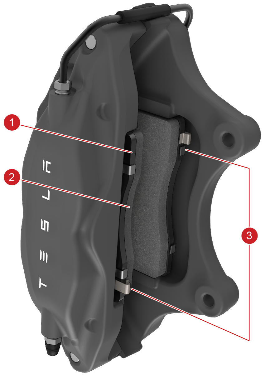
| 1. Steel Backing Plate 2. Friction Material 3. Wear Indicators |
| Front Caliper With Pads |
The brake pads consist of non-asbestos organic friction material bound to a steel backing plate located between the caliper pistons and the rotor. They are equipped with wear indicators which is a thin metal strip attached to the brake pad that squeals as it rubs against the rotor when the pad wears down. This squealing sound indicates that the brake pads have reached the end of their service life and require replacement
Brake Rotorslink
 |
|---|
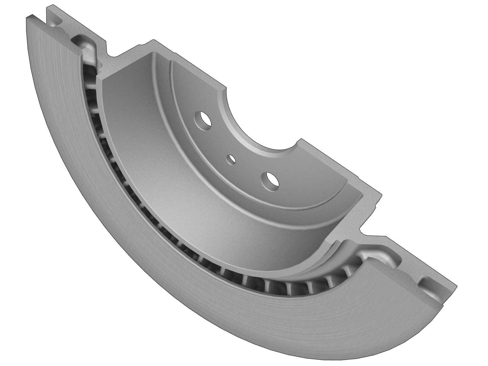
| Brake Rotor |
The brake rotors are of a single piece internally-ventilated cast iron structure treated with a hardening process, these items are non-serviceable. There is a minimum thickness level, please check the online manual for specifications
Brake Pedal and Switchlink
 |
|---|
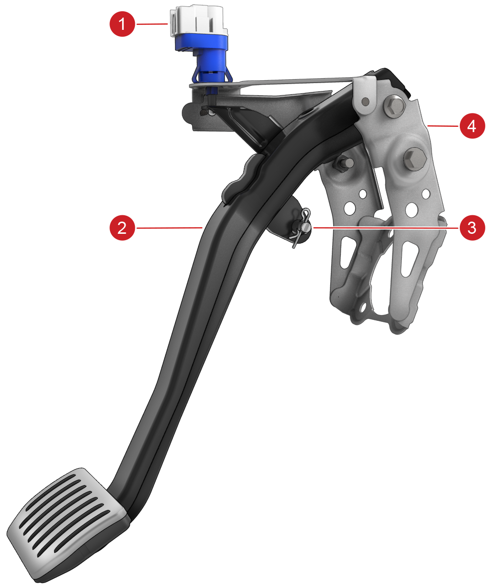
| 1. Brake Switch 2. Brake Pedal 3. Clevis Pin (brake Pedal to Servo Connection) 4. Mounting Bracket |
| Brake Pedal Assembly |
Brake Pedal and Brake Switch mounted together. The brake pedal arm connects to the booster input rod using a clevis pin. The bracket houses the brake switch which senses when the brake pedal arm is pressed.
ESP Hydraulic Unitlink
 |
|---|
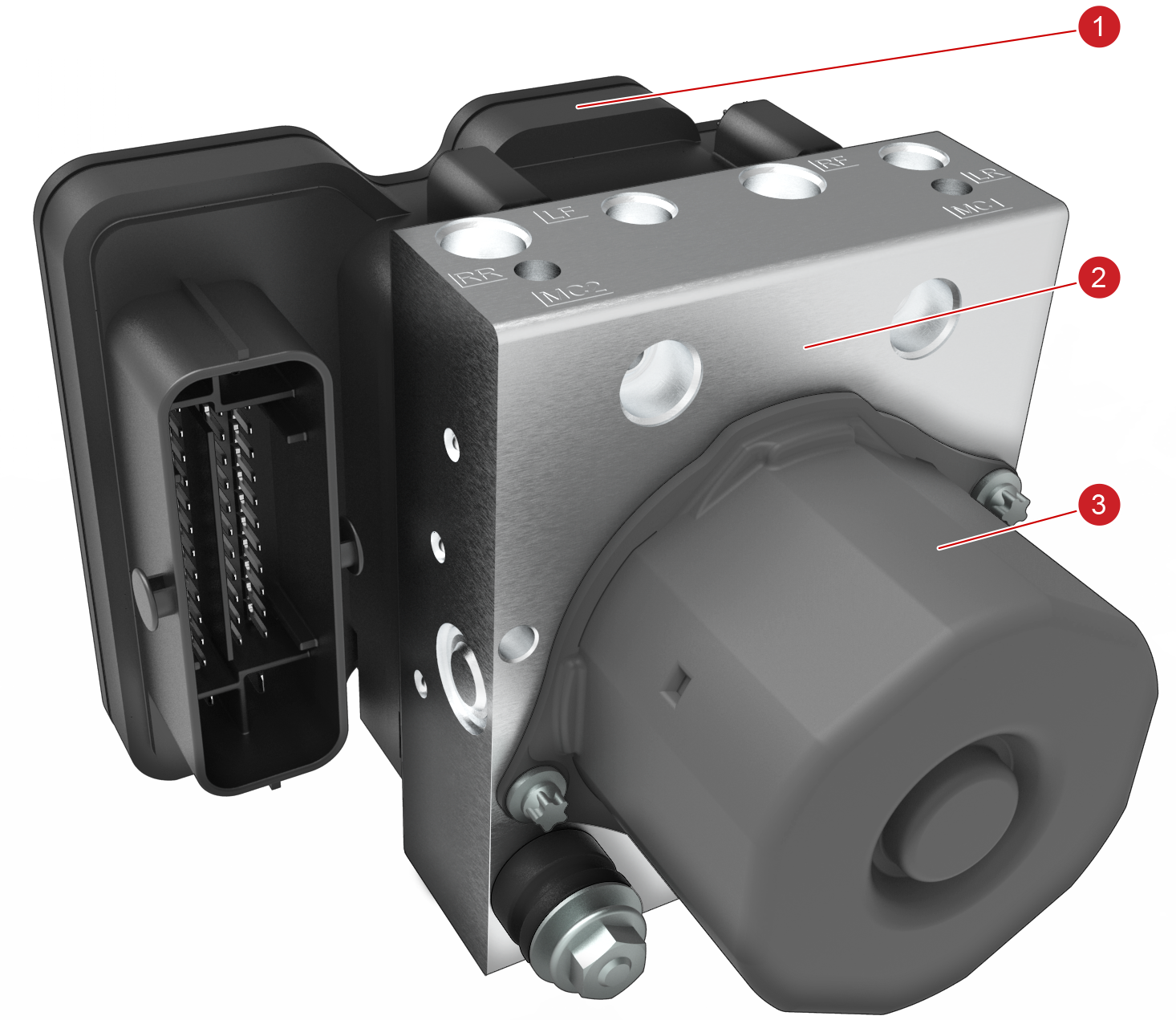
| 1. ECU (Processor and Valve Electronics) 2. Valve Block (Hydraulic Valves and Accumulators) 3. ESP Pump Motor |
| ESP Hydraulic Unit |
The ESP hydraulic unit is fitted on the left-hand side of the front sub-frame cross-member and it consists of three main components:
- The ECU attachment, housing the processor and valve driver electronics
- The valve block, containing the hydraulic valves and accumulators
- The pump motor
It is supplied by two brake lines from each circuit of the tandem master cylinder. Four brake lines exit the valve block and connect to each brake caliper. All six brake line locations are marked on the valve block, indicating the correct hydraulic configuration. The ESP hydraulic unit is not serviceable and is designed to operate for the life of the vehicle. In the event of a fault, the entire unit must be changed
Wheel Speed Sensorslink
 |
|---|
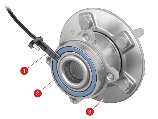
| 1. Wheel speed sensor 2. Sensor tone ring, integrated into wheel bearing 3. Hub |
The wheel speed sensors provide the digital wheel speed signals to the ESP modulator. A wheel speed sensor is installed in each wheel hub unit. The sensing element is situated to align with the magnetic sensor tone ring which is integrated with the inboard bearing. Each contains magnetic elements arranged in pole-pairs that make up the tone ring. Only one side of the bearing contains the integrated tone ring.
 |
|---|
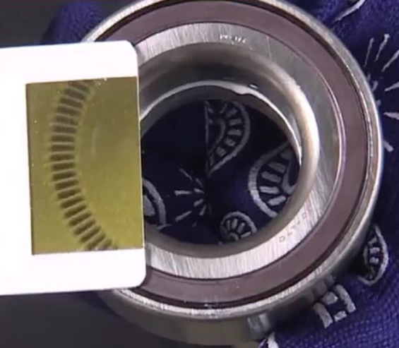
| Magnetic Field Viewer |
As the wheels rotate, the pole-pairs in the seals induce sinusoidal voltage fluctuations in the wheel sensors (the Hall Effect) that are converted into square wave signals. The signal frequency is proportional to the speed of each wheel.
The wheel speed sensors are active sensors. They output a current-based digital signal that has been converted from analogue form, and processed in the sensor unit before being sent to the ESP control unit. This ensures that disturbances and errors in the raw hall effect signals are not passed to the ESP control unit. The pulse width carries further direction and diagnostic information and is not proportional to vehicle speed.
The sensor element is non-serviceable. Most common faults occur because of broken or damaged wiring or connectors, with not operating as expected sensors being less common. Diagnostic troubleshooting indicates the type of fault.
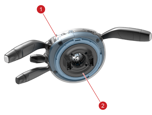
Steering Angle Sensorlink
 |
|---|
| 1. Steering column control module (SCCM) 2. Clockspring |
| Steering Angle Sensor |
The steering angle sensor is part of the Steering Column Control Module (SCCM). The sensor engages the steering column through a pair of detents that locate in slots in the steering column’s outer sleeve when the stalk module is installed, thus centering the module on the column. The steering angle sensor communicates the steering angle to other vehicle systems via the high-speed chassis CAN network.
Note
The sensor is position-sensitive, and MUST be assembled with the steering system in the straight-ahead position. The steering system (column, rack, and tie rods) must be correctly aligned. It is possible to assemble the steering angle sensor incorrectly. No pre-setting procedure is required, provided the sensor is assembled conforming to the assembly procedure.
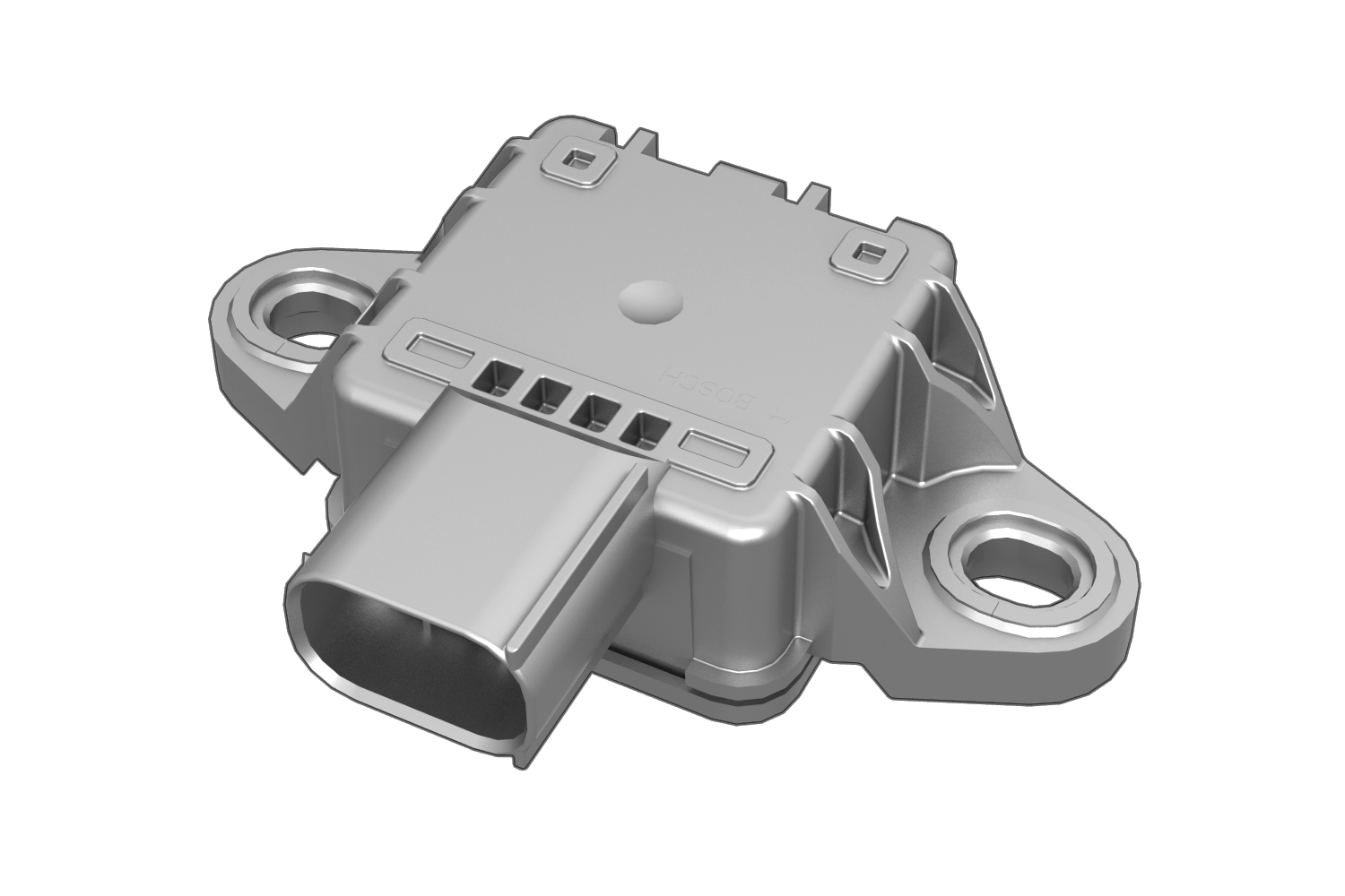
Yaw Rate Sensorlink
Model S up to April 2019link
 |
|---|
| Lateral Acceleration and Yaw Rate Sensor |
The combined lateral acceleration/yaw rate sensor is located under the center console. The sensor is used for ESP operation and measures the vehicle’s rotation around its vertical axis (yaw rate), while at the same time measuring the acceleration perpendicular to the driving direction. The ESP function uses the sensor inputs to detect the onset of side slip during cornering. The sensor communicates to the ESP control unit over the CAN network.
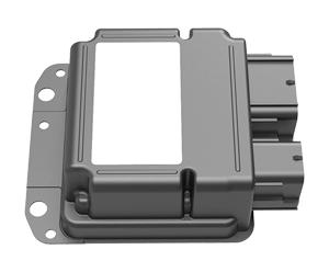
Model S from April 2019link
 |
|---|
| Restraints Control Module (RCM) |
The combined lateral acceleration/yaw rate sensing is incorporated into the Restraints Control Module (RCM) which is located centrally under the center console.
The sensing is used for ESP operation and measures the vehicle’s rotation around its vertical axis (yaw rate), while at the same time measuring the acceleration perpendicular to the driving direction. The ESP function uses these sensing inputs to detect the onset of side slip during cornering.
The RCM communicates to the ESP control unit over the CAN network.
Braking Operationlink
Normal Brakinglink
Pressing the brake pedal applies pressure to the brake fluid in the system. The fluid transmits the pressure unhindered through the normally open inlet valves to operate the caliper pistons. When the brake pedal is released, the springs in the master cylinder return the master cylinder pistons to the rest position, the brake system pressure is relieved, the caliper pistons retract, and the brake pads no longer apply a braking force to the rotors.
Electronic Stability Programlink
The ESP controller constantly monitors and compares signals received from wheel speed sensors located at each wheel hub/bearing. When the brake is applied and a wheel sensor detects it is about to lock (low wheel rotation speed in relation to the other speed signals), the ESP modulator reduces the brake pressure to that wheel enough to prevent wheel locking. As soon as the wheel speed becomes stable, the ESP controller increases the applied brake pressure, thereby maintaining optimal braking force at all times.
The ESP control system performs on each wheel independently. This enables the driver to achieve the highest brake force physically possible, while maintaining vehicle stability and steering.
During normal braking, the feel of the brake pedal on vehicles equipped with ESP is the same as that on non-ESP vehicles. During anti-lock braking (ABS) operation, the driver experiences feedback in the form of a pulsating brake pedal and solenoid/pump motor noise from the ESP modulator. This is normal ESP operation, and the driver does not need to react any differently.
Note
The ABS indicator briefly flashes on first start up during a self-check. If this stays on or comes on during a drive cycle there is an issue in the ESP system and diagnosis is required. Normal braking is fully operational but braking distances and stability will be affected
Traction Controllink
Traction control functions to prevent excessive motor torque from reaching the driven wheels. By monitoring wheel speeds from the ESP, the traction control controller in the Drive Unit Inverter can modulate and reduce motor torque to prevent wheel spin. In cases where one side of the vehicle is driving over a low traction surface (such as patchy ice), traction control can apply the brake at one wheel to stop it from spinning. This enables ascending gradients in conditions where one driven wheel has low grip.

This yellow indicator flashes on the instrument panel whenever the traction control system is actively controlling brake pressure and motor power to minimize wheel spin. If the indicator stays on, a fault is detected with the traction control system.
Traction Control Offlink
Note
Rear Wheel Drive Only
To allow the wheels to spin at a limited speed, disable traction control. Under normal conditions, traction control default is on. Disable it only in circumstances when deliberate wheel spin is required:
- Starting on a loose surface, i.e. gravel/snow.
- Driving in deep snow, sand or mud.
- Rocking out of a hole or deep rut.
To allow the wheels to spin, use the touch screen Controls > Driving > Traction Control > Off.
The touchscreen displays an alert message when traction control system is disabled.

Warning
Traction control system is automatically enabled the next time start cycle
Slip Startlink
Note
Dual Motor Vehicles Only
To allow the wheels to spin at a limited speed, the driver can enable Slip Start. Slip Start can be enabled only when the vehicle is moving 30 mph (48 km/h) or slower. Slip Start automatically disables when the speed exceeds 50 mph (80 km/h). Under normal conditions, Slip Start default is off. Enable it only in circumstances when deliberate wheel spin is required:
- Starting on a loose surface, i.e. gravel/snow.
- Driving in deep snow, sand or mud.
- Rocking out of a hole or deep rut.
To allow the wheels to spin, use the touch screen Controls > Driving > Traction Control > Slip Start.
The touchscreen displays an alert message when Slip Start is enabled.
Warning
Slip Start is automatically disabled the next time start cycle
Electronic Stability Programlink
The ESP function assists the driver in maintaining control of the vehicle during cornering. ESP combines the functions of conventional traction control systems and Antilock Braking Systems (ABS) by using additional data from yaw rate and acceleration sensors in addition to the wheel speed sensors. ESP calculates the intended path of the vehicle based on the driver’s inputs (from a steering angle sensor) and compares it to the measured rate of turn of the vehicle from the yaw rate sensor.
ESP monitors for under-steer or over-steer events during cornering. An interface in drive unit inverter manages drive torque for both traction and stability control functions. In the case of understeering, braking the rear inside wheel results in a positive yaw torque that helps the vehicle turn into the corner. During oversteering, braking the front outside wheel results in a negative yaw torque that steers the vehicle out of the corner and helps the rear axle regain traction. If the vehicle path deviates from the driver’s path, ESP briefly applies the brakes at individual wheels to help steer the vehicle back to the intended path. ESP also controls and limits engine power to the extent necessary to support lateral tire grip during cornering.
ESP works on all road surfaces and weather conditions to help utilize all available road force to keep the vehicle stable. However, ESP cannot evade the laws of physics, and does not prevent loss of control if a driver carries excessive speed into a corner. Furthermore, ESP only assists the vehicle to follow the path the driver is steering. ESP does not prevent the driver from steering a vehicle off the road. ESP activations generally occur during aggressive driving, in the turns or bumpy roads without much use of the accelerator pedal. When braking during ESP activation, the brake pedal will feel different than the ABS pedal pulsation. The brake pedal pulsates at a higher frequency during ESP activation.
Hydraulic Fade Compensationlink
Note
iBooster vehicles only
Hydraulic Fade Compensation (HFC) is designed to help generate brake force in conditions where Brake effectiveness may be reduced due to abnormal environmental circumstances.
Under extreme weather conditions where brake rotors and pads may be subject to excess water, a water film on the brake surfaces could momentarily decrease the performance of the brakes. Road salts used in some winter climates to prevent ice formation can have a mild lubricant effect that may further degrade brake performance.
In such conditions, HFC monitors brake system pressure and ABS-activity to identify instances of low brake performance. Additional brake force can be generated by running the ESP pump to increases hydraulic pressure
If HFC is triggered during heavy braking, the driver may feel a slight drop in brake pedal position, and ABS-like pulsation through the brake pedal, followed with a surge in vehicle braking. This is normal, and indicates the HFC-function is activated. The Amber ABS-active light will also flash during HFC operation.
GTW_w360_espHfcActive in diagnostic logs indicates that HFC system was activated.
Brake Disc Wipinglink
Note
iBooster vehicles only
Brake disc wiping is an automatic assist program that maintains brake responsiveness in cold and wet weather conditions. Brake disc wiping repeatedly applies an imperceptible amount of brake force to clear away water on the brake disc surface. This ensures the brakes are responsive even during poor weather conditions. “GTW_w276_bdwActivated” in diagnostic logs indicates that Brake Disk Wipe system was activated.
Signals taken from the chassis and powertrain controller area networks (CAN) provide data on the following:
- Motor Torque
- Gear Selection
- Brake Pedal Activation
- Vehicle Speed
- Ambient Temperature
- Wiper State
- Battery Pack Temperature
This data is then compared to an internal algorithmto allow brake disc wiping activation command to the ESP. If any CAN faults or relevant signals are SNA then the brake disc wiping request is void until next key cycle.
Warning
This could change with later firmware releases.
Brake disc wipe Mode 1link
Designed to work as vehicle is first driving after being parked in cold conditions (Norway Only). Hydraulic unit will apply “strong” pressure for 5 seconds ON/10 seconds OFF, total of 5 times, as long as:
- Vehicle in Drive
- Positive Motor torque between 0 to 240 Nm
- Road speed greater than 4 mph (6.4) km/h)
- Battery pack temperature -15 to +10 C or Ambient temperature -15 to +10 C
Note
Driver brake apply for 5 seconds will cancel next wipe
Brake disc wipe Mode 2link
Designed to work while vehicle is driving in a variety of conditions. Hydraulic unit will apply “light” pressure for 2 seconds ON at X frequency (minimum 8 seconds OFF), as long as:
- Vehicle in Drive
- Positive Motor torque 0 to 240 Nm
- Road speed greater than 4 mph (6.4 km/h)
X frequency determined by “coefficient of wipe” this is determined by:
- Ambient temperature
- Windshield Wiper state
- Vehicle Speed
Examples: If temperature is warm and there’s no wiper activity, coefficient equals zero (no brake disc wiping) Higher vehicle speed, Windshield Wipers on max speed results in more brake disc wiping
Note
Driver brake apply for 0.3 seconds will cancel next wipe
Vehicle Holdlink
Vehicle Hold can continue to apply the brakes even after the foot brake has been released. After coming to a complete stop, press the brake pedal again until the touchscreen displays the Vehicle Hold indicator light to enable Vehicle Hold. The brake pedal can then be released, the ESP keeps the Brake pressure applied. To disengage Vehicle Hold, press the accelerator pedal or press and release the brake pedal. Shifting into Neutral also disengages the Vehicle Hold Function.

System Faultslink
If the ESP system experiences a malfunction, normal braking is maintained. However, braking distances may increase and wheels may lock under heavy braking. The red and/or yellow brake ABS indicator lights display in the instrument cluster whilst normal driving and errors will be logged