Chassislink
Last updated: October 20, 2023
Wheels and Tireslink
Overviewlink
Wheels are mounted to the suspension at each corner of the vehicle. The tires are mounted to the wheels. The tires transfer vehicle force to the road and are a major factor in a the vehicle's acceleration, braking, handling, range, and comfort performance.
The wheels on Model Y are all cast aluminum alloy with a stylistic coating. If a wheel sustains cosmetic damage to the coating, there is no affect on wheel functionality. Model Y has wheel covers on the 18" wheels, which reduce aerodynamic turbulence to improve range.
Tires are the interface between the vehicle and the road. A tire with a large amount of grip excels at handling, braking, and acceleration but tends to have a higher rolling resistance leading to less range and, due to being softer, has a shorter service life. Modern advanced materials used in tire construction have allowed both higher grip levels and lower rolling resistance to be achieved. Tesla is constantly working closely with tire manufacturers to use the latest technologies for optimal performance and all of Tesla tires are co-developed specifically to meet Tesla's unique performance goals. Tesla specific modifications include re-designed shoulders to reduce aerodynamic drag and a layer of foam to reduce NVH from standing sound waves in the tire cavity.
Wheel and Tire Specificationslink
Tesla does not recommend using aftermarket wheels or tires. Wheels and tires are specifically engineered to meet the requirements of the vehicle. Using aftermarket parts may yield reduced performance in many aspects of the vehicle.
The main specifications for wheel sizes are their diameter and width. Common terminology around wheel sizes are “Square” vs. “Staggered” sizes.
- A square setup in one where the front wheel and tire size is the same as the ones in the rear of the vehicle. This is the default configuration for most cars.
- A staggered setup means that the wheel and tire sizes are different in the front axle than they are at the rear axle. Generally speaking, this means that the rear wheels and tires are wider than the fronts. Higher performance trims will run wider rear tires as they improve traction during acceleration and increase vehicle stability during cornering.
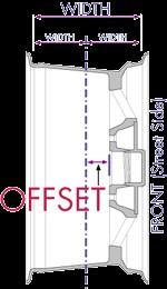
The offset of a wheel refers to the distance from the wheel center line to the mounting surface.
Note
Since the mounting surface of the wheel is fixed, a smaller numerical offset means the wheel is shifted outwards of the vehicle.
Fitting rims with an offset that is different than stock will induce higher loads into suspension components, which could result in damage to nearby suspension and braking components, potentially leading to component failures. An altered offset on the front wheels will change the distance in front view between the king pin axis and the center of the contact patch of the wheel, where both would theoretically touch the road, potentially increasing or decreasing steering effort. Refer to the service manual for offset values.
 |
|---|
| Visual of Wheel Offset |
Tire Sizelink
Tires are sized to appropriately match their rims. The diameter of a tire has to match the diameter of the wheel. A range of tire widths can be used on the same wheel width, however only one tire size is truly optimal for a particular width. If the tire width is not appropriately matched to the wheel, the sidewalls will experience deformation which can lead to increased rolling resistance, lower traction and decreased comfort. Additionally, incorrect tire sizes might result in damage to surrounding components.
After width and diameter, the last specification to a tire size is its aspect ratio, which is the height of the tire sidewall given as a percentage of the tire width. This ultimately impacts the overall diameter (and thus circumference) of a wheel and tire combination. Having a circumference that is different than the specified size will result in inaccurate speedometer readings. Furthermore, if the ratio of front to rear circumferences is changed, the relative speeds of the wheels change causing systems that rely on wheel speed measurements to not function correctly. This includes:
- Automatic Braking System (ABS)
- Traction control
- Launch control
- Tire Pressure Monitoring System (TPMS)
- Drift Pull Compensation
Tire Pressurelink
The most reliable source for the specification of tire pressures for a vehicle is the sticker on the driver’s door jamb. If there is a discrepancy between this information and any other source, default to the information in the door jamb and inform the owner of the other document of the discrepancy. Tire pressures impact grip, efficiency, and comfort. Tire pressures are specified as a Recommended Cold Pressure (RCP) which means that pressures should be checked and adjusted after the vehicle’s wheels and tires have been allowed to cool to ambient temperature (~70° F / ~20° C).
Tire Pressure Monitoring System (TPMS)link
Overviewlink
The Model Y will be the first Tesla vehicle to use our in house designed tire pressure monitoring system (TPMS). The goal of bringing tire sensing technology in-house was to:
- Reduce cost
- Reduce complexity
- Improve design flexibility
The new Tesla TPMS system includes the regular tire pressure and temperature monitoring functionality of the current system as well as additional features to identify other physical parameters of the tires such as tire diameter, width, speed rating, aspect ratio, and tread name.
There will be no separate module for it and it will instead rely on the security bluetooth (BLE) antennas that operate at 2.4 GHz, located in the center console, B-pillars, and rear bumper. The new frequency means that radio frequency sources which did not impact the Continental system may impact system performance. This new protocol and frequency is common worldwide, so there will not be a difference in parts between vehicle markets.
The old wheel sensor units are not compatible with this new system and a new scan tool is used to read the sensor IDs, which are 12 characters long. The new units are also capable of reading pressures while the vehicle is stationary. Although the long term plan is to have automatic detection and localization of wheel units, it is possible manual entry of sensor IDs may be required before the software development is complete. Initial builds of Model Y come equipped with Continental systems as a redundancy during the development phase of the new system.
Definition of terms
| Term | Description |
|---|---|
| BLE | Bluetooth Low-Energy communication protocol. |
| ECU | Electronic control unit. |
| RCP | Recommended cold pressure. This is the pressure that a tire should be filled to at the start of drive. |
| Sensor ID | Identifies the wheel unit from other wheel units |
| TPMS | Tire pressure monitoring system |
| UI or HMI | User interface or human-machine interface. This refers to the instrument cluster or other driver-facing displays. |
| VCSEC | Vehicle security controller - receiver of Tesla TPMS packets |
| Wheel unit / Wheel sensor | The sensor package mounted to the wheel. The wheel unit holds temperature and pressure sensing elements as well as components that send and receive data via wireless communication. |
System Architecturelink
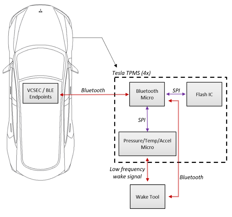
The Tesla TPMS does not have a separate ECU mounted inside the vehicle like the Continental TPMS system used in Model S/X or 3. Instead, the TPMS uses the BLE functionality already built into the vehicle security controller (VCSEC) to communicate with the sensors in the wheels. The wheel sensors communicate absolute pressure in bar and the VCSEC subtracts atmospheric pressure (100 kPa) from the pressure measurements received from the wheel sensors.
Component Communicationlink
VCSEC (TPMS Receiver)
- The VCSEC maintains a connection with the four (4) wheel units during drive and when the vehicle is stationary. If the wheel units are awake, low pressure can be detected.
- The VCSEC receives BLE packets from each of the four (4) wheel units and communicates tire pressure data over CAN.
- The wheel sensor hardware has an operating temperature range of ~ 40 to 105° C.
 |
|---|
| Tesla TPMS Architecture |
Tire Pressure Warnings & Telltalelink
The user facing low pressure threshold warning messages (soft threshold or hard threshold) are displayed to the user via the UI within 5 minutes once a TPMS sensor has connected to the VCSEC and broadcast pressure values.
- Soft low pressure warning is set when the measured pressure is <= 25% below RCP (Recommended Cold Tire Pressure).
- Hard low pressure warning is set when the measured pressure is <= 175 kPa (25 psi).
Note
The process of a TPMS sensor connecting to the VCSEC and broadcasting values requires the vehicle speed to exceed and maintain a speed above 10 mph.
The Security Controller (VCSEC) receives the tire pressures over Bluetooth. It sets the TPMS telltale on the UI to SOLID if the vehicle is in Drive and if any of of the tire pressures is lower than 75% of the Recommended Cold Pressure (RCP). VCSEC sets the TPMS telltale on the UI to OFF if all tire pressures are higher than 90% of the RCP.
The VCSEC shall set the TPMS telltale to flashing for 60-90 seconds, then to solid for at least another 60 seconds if all of the following is true:
- Vehicle is in Drive mode.
- 10 minutes have elapsed while vehicle speed > 25 kph (15 mph).
- 1 or more sensor(s) have not connected and delivered pressure data to the VCSEC.
At the start of the next drive, the VCSEC telltale will flash again for 60-90 seconds before turning solid (until underlying cause is cleared).
Autolearn & Locationlink
The system has the ability to learn and locate new wheel unit IDs during drive and the status of this learning process shall be transmitted on CAN. The autolearn process shall commence if at least 1 previously known wheel sensor does not connect to VCSEC within 5 minutes of the vehicle speed exceeding and maintaining speed above 25 kph (15 mph).
TPMS Autolearn:
- VCSEC shall connect to previously known sensor IDs when vehicle speed > 25 kph (15 mph).
- VCSEC shall unpair unconnected sensor IDs if all 4 previously known sensor IDs do not connect to VCSEC within 150 seconds while vehicle speed is > 25 kph (15 mph).
- VCSEC shall set an alert indicating that autolearn is searching for new sensors. This alert is set if all 4 previously known sensor IDs do not connect to VCSEC within 150 seconds while vehicle speed is > 25 kph.
- VCSEC shall disable BLE MAC Addresses whitelist and search for sensor IDs in autolearn mode if < 4 sensor IDs are paired and vehicle speed is > 25 kph. Autolearn shall continue to run until 4 sensor IDs are paired.
- VCSEC shall pair a sensor ID if its advertisement is verified as a Tesla TPMS sensor while in autolearn mode.
- VCSEC shall enable BLE MAC Addresses whitelist and stop autolearn if 4 sensor IDs are paired or vehicle speed .
TPMS Autolocation:
- VCSEC shall determine the corner location of each connected sensor within 10 minutes while vehicle speed > 25 kph (15 mph).
- VCSEC shall transmit sensor location on CAN.
- The UI shall display pressures in the corner locations determined by autolocate during the previous drive.
- The UI shall update the locations of pressure values / highlighted text to reflect the updated location of TPMS sensors when autolocate completes if the result differs than the previous autolocate result.
Tire Wearlink
Tire treads wear over time, thus reducing performance. This reduced performance is especially hazardous in wet or snowy conditions. Most tires come with tread indicators, which are a special pattern on the side on the tread blocks that show when the minimum acceptable tread depth has been reached.
Serviceabilitylink
Wheels are not serviceable in any way and must be replaced if damaged. Some curb rash is acceptable and generally considered just cosmetic. Deep gouging, cracks, or off round wheels are indications of impact, and their source should be investigated. If a wheel is damaged, the rest of the vehicle should be inspected for damage as well. Even if the suspension looks unharmed, the alignment should be checked. A tire that does not hold pressure may also be caused by a damaged wheel.
The primary service that tires require is regular top offs to maintain a correct pressure. Low pressure can reduce range and the excess heat generated may even destroy a tire. High pressure can cause undesirable handling behaviors and decrease tire service life. Tires are wear items and thus should be replaced regularly. Tires wear down due to both mileage and age. A high mileage tire will wear away the tread and become unsafe in wet, snowy or icy conditions. Even in areas with low precipitation, tires without enough tread depth may become a hazard if puddles form for whatever reason.
When replacing tires on a wheel, the tire must also be balanced. Balancing involves using a machine to measure the amount and direction of vibration a wheel and tire combination has when spun up and then using this information to attach weights to the wheel to offset the imperfections. Refer to the service manual for instructions on balancing a tire.
Steeringlink
Overviewlink
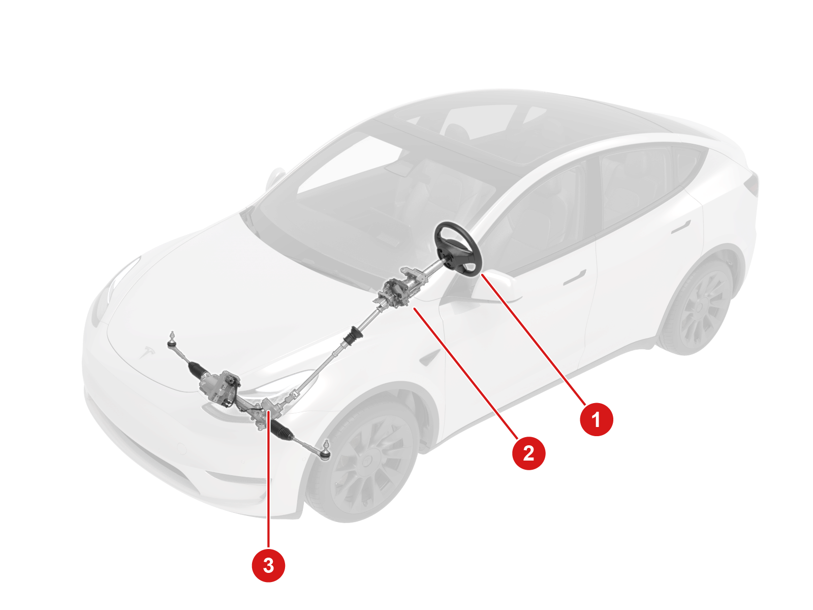
The steering wheel connects to the steering rack through a column. The rack is bolted to the front subframe and through tie rods connects to and articulates the knuckles, which hold the wheels and tires.
 |
|---|
| 1. Steering Wheel 2. Steering Column Assembly 3. Steering rack assembly |
| Component Location Overview |
Electric Power Assisted Steering (EPAS) is a system that provides steering assistance for turning the front wheels on Model Y. This system primarily uses torque input from the driver to determine how much assist the electric motor should provide. Other inputs include the selected steering feel mode, absolute steering angle from the column and vehicle speed. EPAS is energy efficient and can be used for self-driving as well.
Component Specificationslink
Steering Columnlink
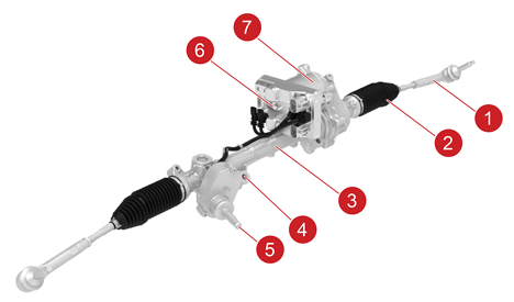
The steering input column translates the motion of the steering wheel into the EPAS unit. The input goes through a torque sensor that is read by the ECU and is the primary input for control. The input is also mechanically connected to the rack and pinion and will continue to allow for directional control in case of a complete assist system failure. The ECU reads the torque as well as other parameters and drives the 3 phase brushless motor. The motor connects to the rack through a belt drive actuating a recirculating ball mechanism. The rack connects to and actuates the knuckle through an adjustable length tie rod.
 |
|---|
| 1. Outer tie rod 2. Inner tie rod 3. Steering rack 4. Torque sensor 5. Input shaft 6. ECU 7. Motor |
| Steering Column, Overview |
Torque Sensorlink
Consists of a tuned torsional spring and 4 hall effect sensors. The sensors measure the twist of the spring and calculate the input torque from this. The spring has a mechanical stop that solidly connects the input shaft to the pinion when it reaches the end of its travel. The sensors work in pairs, like the pedal position sensors; they are oriented inversely so that when one reads 100% the other reads 0% and vice-versa. If there is a mismatch from expected behavior, then a plausibility error is thrown. There are 2 such pairs of sensors for redundancy. Below is a visual explanation of how the plausibility check works. If either pair fails this check, the other is used and an error is thrown to warn of the failure
Motorlink
Model Y has a 3-phase, brushless motor, known for good reliability and power density characteristics. The motor attaches through a belt drive to a recirculating ball mechanism to actuate the rack. This design has low friction and very little slop, but the precisely set tension of the belt means the motor cannot be replaced in the field.
Steering Rack (EPAS) ECUlink
The EPAS ECU reads the torque as its primary input and runs control algorithms to ensure the motor provides optimum assist at all times. The ECU is the same for all Tesla vehicles equipped with Driver Assistance 2.5 and above hardware.
The primary ECU controls the motor. If there is a suspected error or communication issue on ECU1, then ECU2 takes over. Each ECU has its own torque sensor and inverter circuitry to drive the motor and when control is handed off, the phase disconnect cuts the connection to the motor for one ECU and makes the connection to the other. The ECUs have individual connections to the electrical systems of the vehicle so that if one bus or electrical connection is lost, the system will still continue to operate.
The primary ECU is connected to the Party Bus (Secondary CAN) while secondary ECU is connected to the Chassis Bus (Primary CAN) and an internal bus between them relays the messages the other is not receiving.
The ECU takes in other, secondary inputs in order to tailor its behavior. Information from the user interface (UI) informs the ECU of the level of assist the driver desires. Speed information from the drive inverter also impacts the level of assist, with more being provided at low speeds. Data from the steering column control module (SCCM), electronic stability program (ESP), and the restraint control module (RCM) is combined to get an estimate of the direction of the vehicle and minor adjustments are made to compensate for offsets in the alignment of the vehicle. The front vehicle controller (VCFRONT) provides information regarding the electrical and power state of the vehicle.
Lastly, the DAS module can directly request steering outputs for autopilot features. The most critical systems communicate with the EPAS over two buses in order to provide redundancy in case of various failures. It is important to note that EPAS behavior relies on data from many different systems.
Applied Angle Offsetlink
The EPAS doesn’t have an internal absolute position sensor and thus relies on the SCCM to set the “0” point. After the initialization the rack tracks it’s angle internally. In order to compensate for minor alignment issues the EPAS will calculate and apply an angle offset to the SCCM “0” point. This applied offset will always show up as a difference in steering angle between the SCCM and the EPAS. The goal of the offset is to make it so that the vehicle drives straight when the steering rack angle is 0. High applied offsets can indicate alignment issues and the applied angle offset must be cleared after bringing alignment into spec.
Pull / Drift Compensationlink
This function attempts to reduce the steering hand wheel torque that the driver applies while driving in a straight line. This function aids the driver by compensating for the accumulated effects of various factors, such as road crown, that contribute to the pull / drift of the vehicle. This is achieved by the application of a counter torque from the EPAS system. The vehicle will drift less when the driver's hands are taken off the steering hand wheel, and steering straight ahead holding effort is reduced.
There are two sub-compensation components: pull / drift long term compensation and short term compensation.
-
Long term is designed to learn very slowly and is always applied when driving at speed. It is meant to compensate for drift and pull introduced by chassis asymmetries like alignment and tire pressure. Long term compensation torque usually changes less than 0.1Nm in a minute at steering wheel level.
-
Short term is designed to learn quicker and is only applied when driving straight at speed. It is cleared when steering high angles and during autopilot. Short term is meant to compensate quick change of external disturbances like change of road crown, side wind. Short term could change as much as 1Nm in 10 seconds at steering wheel level if facing strong disturbance.
Serviceabilitylink
Individual components can not be serviced; the system must be replaced as a whole. Certain alerts can indicate with certainty that there are internal faults, however it is important to note that this system is designed to be very robust. Before replacing an EPAS unit, it is important to understand if the failure mode that occurred is internal to the unit or may have been caused by issues with the data from the other systems it relies on.
Suspensionlink
Overviewlink
The suspension is the mechanical linkage that connects the wheels and tires to the front and rear subframes. The subframes are attached to the body.
A vehicle’s suspension controls tire motion, absorbs energy from the road, and reduces vibration from road imperfections. The Model Y uses multilink suspension in the rear and a variation of the double wishbone design on the front. Although complex, these suspension geometries allow great design freedom to tune the suspension to optimally split the difference between immediate response and ultimate cornering grip, and comfort. The system is comprised of both steel and aluminum with each piece being analyzed and optimized for its task. Due to manufacturing variability and wear over time, the alignment of the wheels with respect to each other may require adjustment. The most important alignment parameter, toe, has built in adjustment mechanisms. Additional alignment values might be changed with longer procedures or worn component swaps.
Component Specificationslink
Front Suspensionlink
The front suspension is a variation of the double wishbone design. This geometry is widely used in higher end cars and racing because it allows for independent tuning of multiple parameters of the suspension. The double wishbone design usually consists of a short upper control arm and a longer lower control arm, however in the case of the Model Y, the lower link is actually comprised of 2 links. This variation moves the steering axis of rotation of the front tires in such a way as to make the vehicle more stable and planted. The 2 lower arms are aluminum forgings that connect to an aluminum knuckle which houses the wheel hub. The knuckle is tall in order to transfer most of the lateral loads from the tire through the two lower links, while the upper arm experiences less load.
Depending on the build, the shock absorber and the front upper control arm (FUCA) bolt directly to one of the following:
-
Non-structural pack Model Y - A structural reinforcement called the FUCA mount that is then bolted onto the vehicle body.
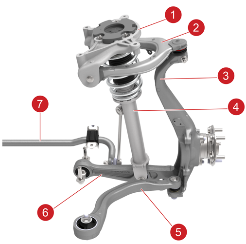
1. FUCA mount
2. Upper control arm
3. Knuckle
4. Shock absorber (RWD variant shown)
5. Lower compliance link
6. Lower lateral link
7. Stabilizer barFront Suspension, Non-Structural Pack Model Y -
Model Y Structural Pack - Single cast front under body (FUB)
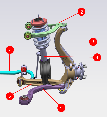
2. Upper control arm
3. Knuckle
4. Shock absorber (Dual Motor variant shown)
5. Lower compliance link
6. Lower lateral link
7. Stabilizer barFront Suspension, Model Y Structural Pack
The front damper and spring come together as one assembly and connect to the lower lateral link. A spring steel stabilizer bar exists in order to tune the roll stiffness of the front suspension. The upper arm and the lower lateral link are mostly responsible for the camber and camber curve of the wheel. The lower compliance link is mainly responsible for the caster, which can be adjusted by moving the FUCA mount (only on non-structural Model Y). The steering rack connection to the knuckle is through a tie rod that is adjustable in length, allowing for adjustment of the front toe. The lower links and the steering gear are all connected to a structural member called a subframe that is made of stamped and welded steel and provides a mounting structure between the body and the suspensions.
Note
All the front suspension links and the front upper control arms (although different material) are compatible between Model Y Structural Pack and non-structural Model Y. However, the front subframes have different mounting points between the two variations and therefore are not compatible.
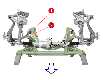 |
|---|
| 1. Subframe 2. Tie rod Note: Blue arrow points to the front of the vehicle. |
| Subframe of Non-Structural Model Y |
The use of a subframe provides extra rigidity in the body for mounting suspension links and is an important part of crash management. The subframe also simplifies the manufacturing process, allowing the entire front end to be built as a unit and mounted to the body. It also provides mounting points for things such as a steering rack and the front fascia.
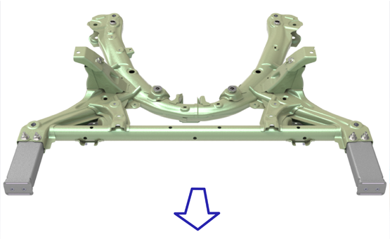 |
|---|
| Note: Blue arrow points to the front of the vehicle. |
| Front Subframe of Non-Structural Model Y |
Rear Suspensionlink
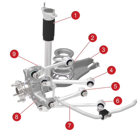
The rear suspension is a multi-link set up comprised of 5 arms. The arms are all steel and either tubes or stamped. They connect to an aluminum knuckle which houses the wheel hub. The high strength steel arms are effective at transmitting loads while the aluminum knuckle reduces unsprung weight. The spring and damper are split but both connect to the lower aft link. The spring is a larger diameter but lower profile while the strut is thinner but longer; by splitting them up they can be packaged to allow for much more interior space in the trunk for storage.
 |
|---|
| 1. Damper 2. Spring 3. Lower compliance link 4. Upper fore link 5. Toe link 6. Lower lateral link 7. Stabar 8. Knuckle 9. Upper aft link |
| Rear Suspension, Overview |
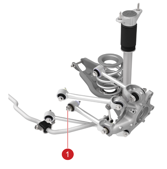
The upper and lower aft links are mainly responsible for the camber and camber curve of the wheel. The fore links are responsible for the longitudinal and rotational movement of the wheel. The toe link is responsible for pointing the wheel and is the only adjustable link. There is a cam bolt on the inboard side of the toe link to allow for alignment.
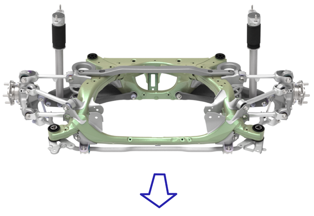
The rear subframe is a stamped and welded steel structure. It provides the hard mounting points for the suspension and the rear drive unit. The subframe connects to the body in white via 4 large, main bushings. This arrangement allows the subframe to both distribute the loads from the suspension into the main structures within the unibody, as well as to isolate the cabin from road inputs and drive unit vibration.
Note
The rear suspension and subframe are compatible between Model Y Structural Pack and non-structural Model Y (single cast Rear Under Body - RUB). The only difference are the two Shear Plates (different profile).
 |
|---|
| Note: Blue arrow points to the front of the vehicle. |
| Rear Suspension Attached to Body-in-White |
 |
|---|
| 1. Cam bolt |
| Rear Suspension Toe Adjustment |
Serviceabilitylink
The suspension is serviceable by individual component replacement. If issues arise with any of the suspension links or their integrated bushings, the whole link must be replaced. The same is true with the subframes and the clevis mounting points. After suspension components are loosened, it is important to align the suspension to ensure the vehicle stability and correct tire wear.