Non-Structural High Voltage Batterylink
Last updated: December 11, 2024
Overviewlink
The high voltage (HV) battery is the primary energy storage device in the vehicle. Its main purpose is to provide power to the powertrain for all vehicle operations.
The HV battery hosts several key components of the powertrain that are vital for vehicle functions like driving, charging, and providing power to the vehicle low or medium voltage (referred to as LV or MV) systems.
Warning
The HV battery has a lot of energy stored in a small volume. Use extreme care when handling HV batteries.
Location of the High Voltage Batterylink
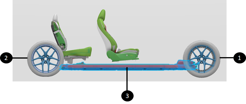
The HV battery is mounted to the chassis bottom for easy removal and installation, improving vehicle dynamics with a lower center of gravity.
The HV battery is not designed for rapid HV battery swapping, nor does it have HV rapid mate connectors between the HV battery and the HV powertrain. The HV battery has latch-on HV connectors, and the coolant hose connections are clamped (not via rapid mate).
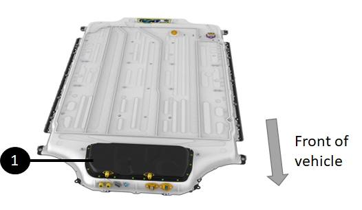
 |
|---|
 |
 |
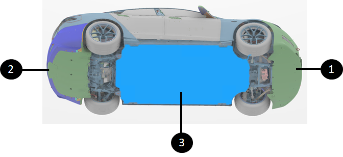
| 1. Front of vehicle 2. Rear of vehicle 3. HV battery |
| HV Battery Location |
Pack Generationslink
Below are the different generations of Tesla HV batteries:
| HV battery Generation | Applicable Models |
|---|---|
| Gen 1 | 2012-2020 Model S 2015-2020 Model X |
| Gen 2 | Model 3 Model Y (Non-Structural and structural HV batteries) |
| Gen 3 | 2021+ Model S 2021+ Model X |
| Gen 4 | Cybertruck |
The Gen 3 HV battery was introduced on the 2021+ Model S and Model X vehicles. At launch in early 2021, there was only one configuration of the HV battery for both Long Range (Dual Motor) and Plaid (Tri-motor) configurations. The same HV battery can be used for all configurations and all markets (three-phase and single-phase) by using a dummy plug at the HV battery on the second rear HV drive unit connector for the Long Range (Dual Motor) configuration and another dummy plug on the 3-phase connector
Note
Until mid-2022 when 2021+ Model S and Model X vehicles were shipped to EMEA and APAC, the HV battery produced was North America only and did not have a 3-phase plug.
Pack Architecturelink
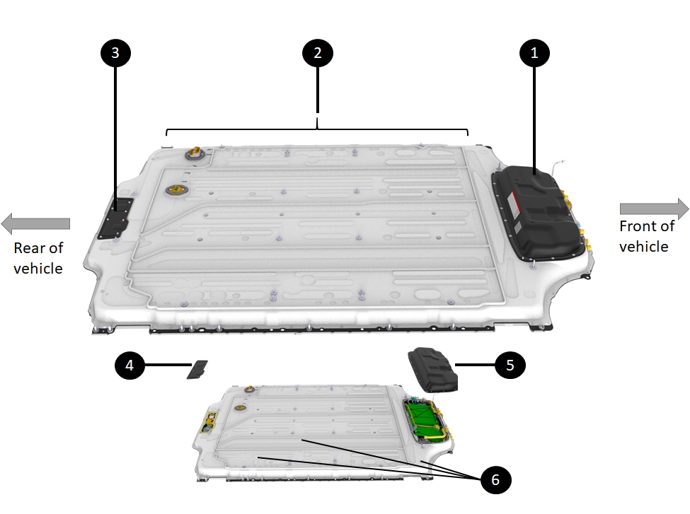
The HV battery consists of the four distinct sections:
- The module platter
- The Ancillary Bay
- The rear access service panel
- The pyro-disconnect area
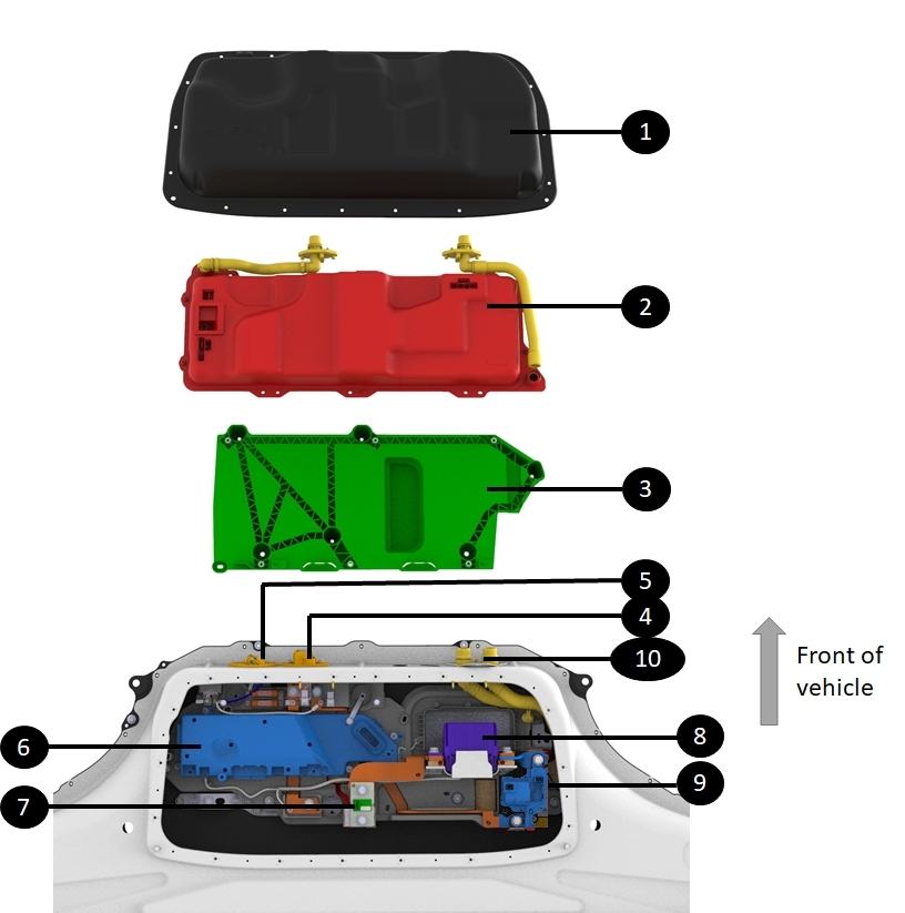
The HV battery module platter includes battery cells and thermal management components, and the Ancillary Bay holds electronic components known as "high voltage devices." For more details, see HV Devices Theory of Operation.
 |
|---|
| 1. Front Ancillary Bay 2. HV battery Platter (under the cover) 3. Rear Access Service Panel 4. Rear Access Service Panel Cover 5. Front Ancillary Bay Service Cover 6. HV Battery Enclosure |
| HV Battery Architecture Sections (With Service Access Shown) |
Battery Platterlink
The HV platter is the large area of the battery that is below the Ancillary Bay and inside the enclosure. It contains the modules, high voltage distribution links, and thermal elements of the HV battery. The High Voltage Devices of the HV battery are located in the Ancillary Bay. The only piece of HV electronic that is not in the Ancillary Bay is the set of Battery Monitoring Boards (BMB) which are located in the modules of the HV battery. See item number 2 on the figure above to locate the platter.
The platter contains all the cells which have a minimum voltage of 2.5V closed circuit and a max voltage of 4.2V open circuit. With a s-count of 110, the HV battery has a minimum voltage of 275V and a maximum of 462V.
The cells used in the HV battery have 12.84 Wh of capacity and can only charge when internal temperature is above 32 degrees Fahrenheit (0 degree Celsius). With all the cell capacities combined, HV battery energy capacity is around 101.6 kWh
Warning
The top cover is not removeable in service. The top cover is bonded to the enclosure and all cell-arrays with adhesive. The cover cannot be removed without being damaged. Only specifically trained personnel shall remove the HV battery cover.
Note
For more information about the Ancillary Bay, refer to the Ancillary Bay Theory of Operation.
Ancillary Baylink
The Ancillary Bay contains most of the HV electronics in the HV battery used to control the HV system of the vehicle. This includes:
- Powering up the HV system of the vehicle
- Charging the vehicle HV battery
- Providing power to the low- voltage system
- Managing power available for the HV system
- Managing HV system failures
- Managing thermal condition of the HV battery
The Ancillary Bay allows access to most components of the HV battery, aside from modules and the platter thermal cooling system.
The Ancillary Bay contains:
| HV Device | Purpose |
|---|---|
| Power Conversion System (PCS) |
|
| High Voltage Controller (HVC) | Includes the High Voltage Battery Management System (HVBMS) and High Voltage Processor (HVP) |
| Fast Charge Contactors | Connect the HV battery to the charge port for DC charging |
| Pack Contactors | Connect HV from modules to vehicle powertrain |
| HV Shunt | Measures HV current |
| HV Pyro-disconnect |
|
| Charge inlet connector | Connects PCS input to the charge port |
| HV fuses |
|
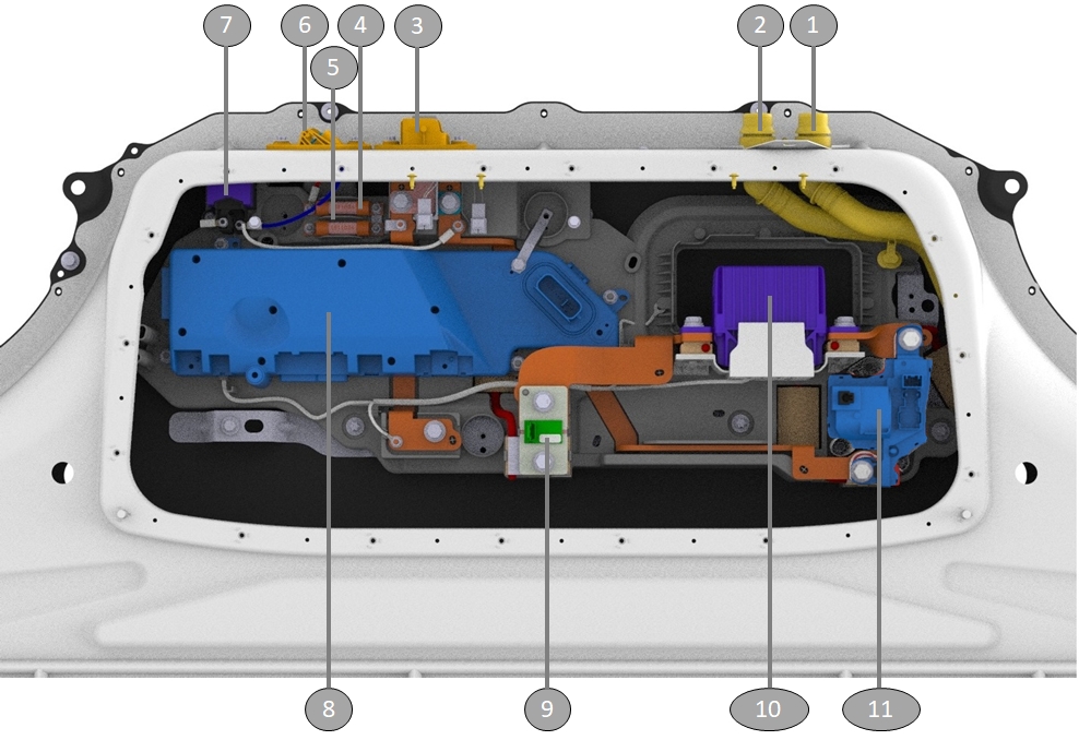
 |
|---|
| 1. Front Ancillary Bay cover 2. PCS 3. Tray for PCS mounting 4. Front Drive Unit HV connector 5. Heat pump compressor HV connector 6. High voltage controller 7. Shunt 8. Pyro-disconnect 9. Negative contactor 10. Coolant manifold for module coolant loop |
| Exploded View of Front Ancillary Bay Components |
 |
|---|
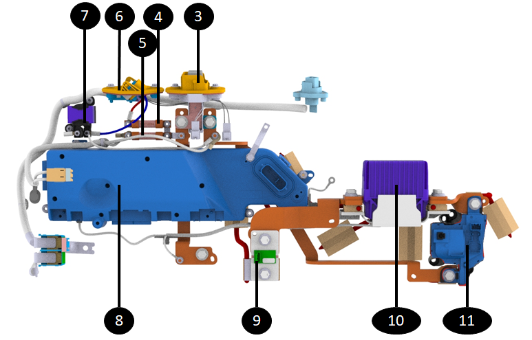 |
| 1. Platter coolant input manifold 2. Platter coolant output manifold 3. Front drive unit HV connector 4. Heat pump compressor 63A fuse 5. PCS 63A fuse 6. Heat pump compressor HV connector 7. Compressor EMI noise reducer 8. High voltage controller 9. Shunt 10. Pyro-disconnect 11. Negative contactor |
| Detailed View of Ancillary Bay Internals |
The front Ancillary Bay has a service access cover allowing quick access to the HV devices within the Ancillary Bay . The cover is removable and can be found once the HV battery has been dropped from the vehicle.
A dedicated cover under the vehicle allows for easy access to the pyro-disconnect, enabling replacement without removing the HV battery or Ancillary Bay cover, often after any airbag or pretensioner deployment.
 |
|---|
| 1. Front Ancillary Bay with its access cover |
| **Front Ancillary Bay ** |
High Voltage Interfaceslink
The HV battery integrates the functionality of the on-board charger, DCDC converter, High Voltage Junction Box (HVJB), and Front Junction Box (FJB) to receive and transmit signals to most powertrain electronic control units (ECUs) in the vehicle and powers on bank of the low- voltage system through the power conversion system. To achieve all this, the following interfaces exist on the HV battery:
 |
|---|
| 1. HV Plug for Rear Drive Unit HV cable (connector reference RDULEFT-HV-AT-HVBATT) 2. HV Plug for Right Rear Drive Unit HV cable (connector reference RDURIGHT-HV-AT-HVBATT) - Dummy plug for Dual Motor configurations 3. Three phase charge inlet connector 4. Charge inlet connector 5. PCS coolant inlet passthrough 6. Platter coolant passthrough 7. Logic connector 8. 12V passthrough 9. Front Drive Unit connector at HV battery (connector reference FDU-HV-AT-HVBATT) 10. Ancillary HV connector (connector reference CMP-HV-AT-HVBATT) 11. PCS coolant outlet passthrough |
| HV battery interfaces |
Moduleslink
Specificationslink
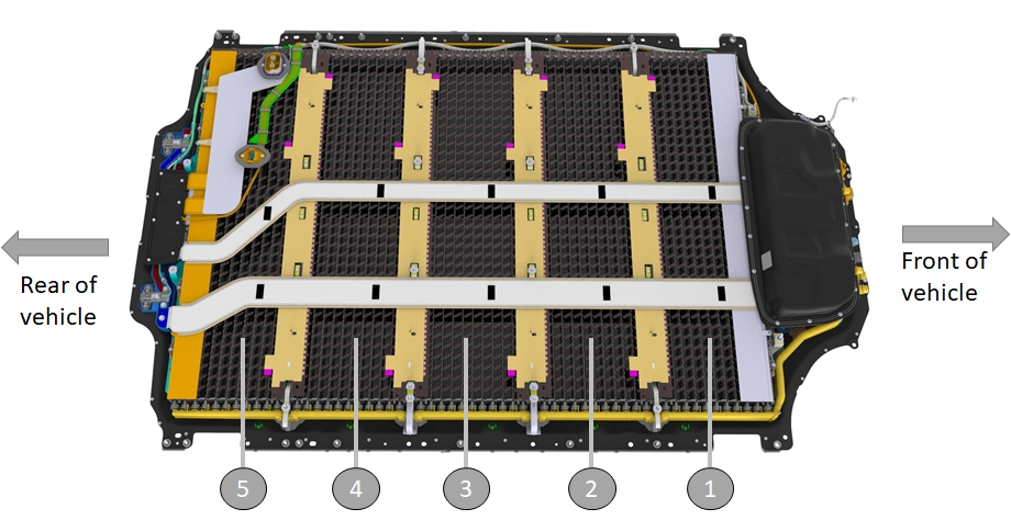
The HV battery is made of 5 independent modules that are seated in the entire width of the HV battery enclosure.
The module contains the cells of the HV battery and it is the source of energy and power for the vehicle.
Each module is made of 22 bricks in series which sums up to a voltage of 80V per module. A brick contains a group of 72 cells connected in parallel. The Model S and X (2021+) HV battery has one unique module part number, the 5 modules are identical.x`
 |
|---|
| 1. Module 1 (most negative) 2. Module 2 3. Module 3 4. Module 4 5. Module 5 (most positive) |
| HV Battery Modules in the Platter |
Operationlink
Cellslink
Cells are the source of energy and power for the vehicle.
The HV battery has an internal structure of lithium ion cells linked together in combination of parallel and series to reach the desired level of energy and power required.
The lithium ion cells have a high energy density (Wh/kg), about 2 to 3 times the energy density of a nickel-metal hydride battery and 6 times the energy density of lead acid battery. Lithium ion cells are agnostic to charge and discharge patterns. When not in use, lithium ion cells self-discharge and have a flat discharge curve, meaning they have linear power capability even at half charge level.
Rechargeable batteries perform reversible electrochemical reactions at the battery’s positive and negative electrodes. The battery is charged by applying an electric current.
During discharge, lithium ions de-intercalate from the negative electrode and move through a separator to intercalate in the positive electrode. When charging, the reverse occurs. Lithium ions de-intercalate from the positive electrode and move through a separator to intercalate in the negative electrode.
The cells used in the HV battery have a 18650
| HV battery Generation | Configuration | Cell Type | S-Count | P-Count | Total Cells in Pack |
|---|---|---|---|---|---|
| Gen 3 | Plaid / Long Range | 18650 | 110 | 72 | 7920 |
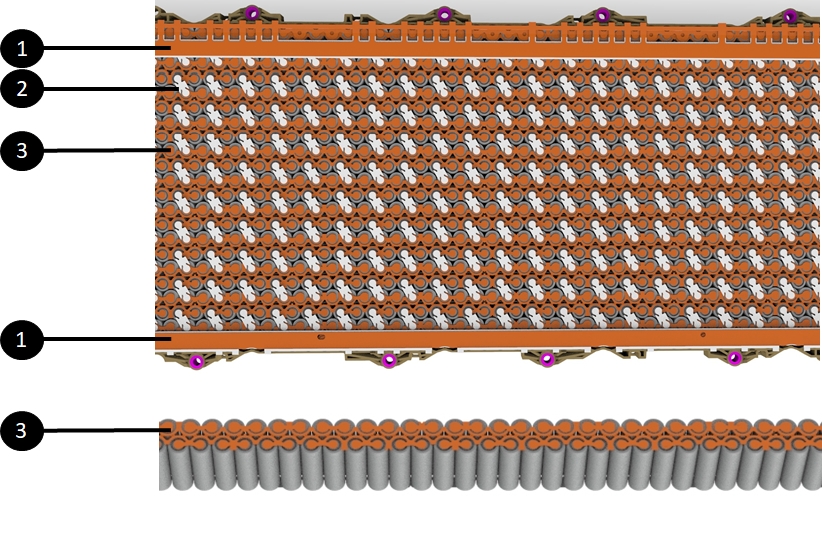
Bricks in Bandolierslink
A brick is a group of cells connected in parallel. Linking cells in parallel adds current from each cell to increase current capability and the amp hour count (the unit for measuring the energy capacity of a battery).
The bricks are connected in series in a module to increase voltage. The modules are also chained together in series to further increase voltage and power capability.
A bandolier refers to one or two strings of cells against a cooling tube. A module is made of 11 bandoliers.
Note
Cells on the HV battery are close to each other and could end up touching. To prevent a brick to brick short, each cell of a HV battery module has an insulating sleeve around it. Each side of the bandolier is wired fully in parallel as one single brick. Each bandolier is two bricks, one on each side of the cooling tube.
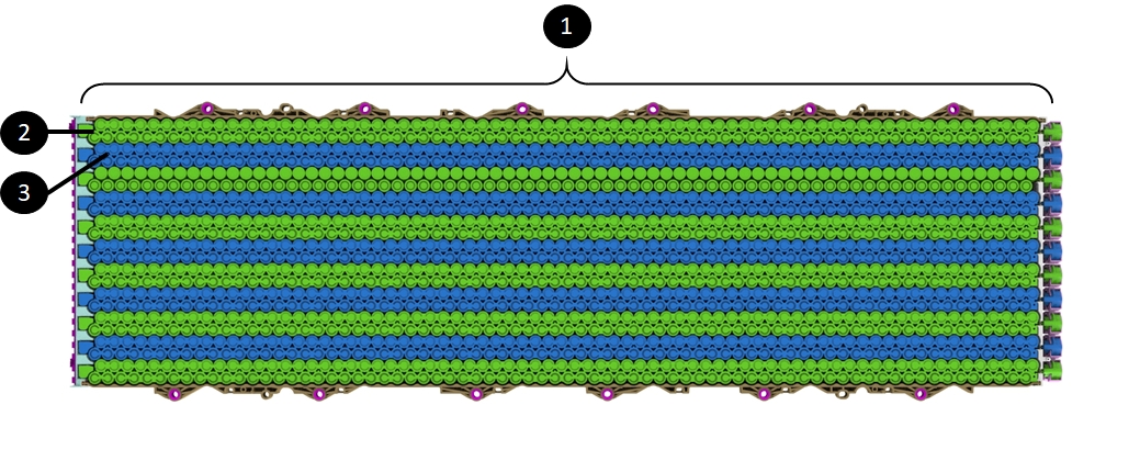 |
|---|
| 1. Module 2. One bandolier 3. Next bandolier |
| Bandoliers per Module |
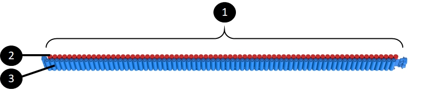
The bricks are made of one row of cells that runs the entire width of the module. This allows for linear current flow among the cells without spots where current would get concentrated, like bolted joints.
The diagram below shows 2 bricks mounted on a bandolier with 72 cells per side.
 |
|---|
| 1. Single bandolier 2. First 72 cell brick of the bandolier 3. Second 72 cell brick of the bandolier. |
| Two Bricks per Bandolier |
The cells in the bandolier are positioned vertically and oriented in both directions (one brick with anode facing up and the next brick with anode facing down).
The size and orientation of the cells are reconstituted from the predecessor Gen 2 pack:
- The cells are 1865 type, measuring 18mm in diameter and 65mm in height, with internal differences from Gen 2 cells that enable increased power.
- By contrast, the Model 3 / Model Y HV battery uses a 2170 cell format, or 21mm in diameter and 70mm in height.
- The Model S and X (2021+) HV battery cells are positioned vertically in the module and oriented in both directions (one brick with anode facing up, and the next brick with anode facing down).
Note
that this is different from the Model 3 / Model Y HV battery, where all cells are oriented in the same direction.
Each brick's cells are connected in parallel to dual current strips (positive and negative) on both the top and bottom, enabling efficient current collection.
Brick interconnects, also known as "dog bones," connect adjacent bricks along the bandolier, facilitating electrical connections between them (only present on the top side of the module).
 |
|---|
| 1. Module current collectors (connected to module terminals) 2. Brick interconnects (sometimes referred to as "dog bones") 3. Current strips linking cells into a brick (orange) |
| Two bricks per bandolier |
Each module has a long battery monitoring board (BMB) that runs its entire width (the predecessor Gen 2 HV battery module had a much smaller BMB). Each Model S and X (2021+) HV battery BMB is connected to each brick of the module to measure all 22 brick voltages. The brick pattern of the Model S and X (2021+) HV battery module allows the BMB to directly connect to the current strips without using any leads. This direct connection lowers the risk of voltage sense harness issues from severed sense leads.
The BMB is also equipped with two thermistors to measure temperature of the module. The two thermistors are located on the side of the BMB PCBA that is against the module. The location is close to the extremity of the cooling tubes compared to the manifold (on the opposite side of the module compared to the BMB).
Modules are separated by a cross member running length wise in The HV battery. There are three inner longitudinals between each module and two outer longitudinals between the outer modules and the edge of the battery. The outer longitudinal protects the modules during side vehicle impacts.
The top of the cells of each brick are spot welded to two current collectors.
- One current collector is connected to two bricks (positive of one brick and negative of the other one).
- A single collector will be connected to cells.
- Half of a collector will be connected to the can of the cells (anode) and the other half are connected to the center tab (cathode).
The current collector performs the following functions:
- Electrically interconnects cell-arrays in a series of parallel groupings,
- Distributes current between all cells in a given parallel grouping,
- Allows terminal voltage sensing, at a single point, for all cell in a given brick,
- Conducts peak and continuous operating currents between each cell and array,
- Fusing protection for HV shorts.
High Voltage Chainlink
Current and power accumulate along the cell-array, beginning at the first brick on the most negative end and growing to the positive end of the array, with HV terminals at each end to facilitate connection.
Note
The front terminals are designed to fuse under short circuit events at the cell-array level.
For detailed information on how the voltage builds up in the HV battery, refer to the HV Architecture Theory of Operation
Serviceabilitylink
Modules are not serviceable because they are embedded within the platter area, making them inaccessible due to the structural HV battery's bonded top and bottom enclosures.
Battery Management Boardlink
Specificationslink
A BMB is a Printed Electrical Circuit Board (PCBA) with various electrical components on it. The primary functions of a battery monitoring board (BMB) are:
- Measuring voltages of the bricks in a module
- Measuring temperatures of modules in one or several locations
- Balancing bricks charge level amongst other bricks
BMBs are connected to both sides of each brick in a module.
The wires linking current collectors to BMBs are consolidated into a flexible ribbon cable called the Voltage Sense Harness (VSH).
 |
|---|
| 1. BMB PCBA 2. Thermistor directly on BMB |
| Battery Monitoring Board Overview |
BMBs have two thermistors mounted directly on the PCBA close to where the bandolier cooling tubes contact the BMB PCBA. The temperature of the module can be measured without requiring extra wiring between BMBs other locations on the module.
BMBs connect to each other via a daisy chain which itself is connected to the high voltage controller (HVC). Temperature and brick voltage measurements from BMBs travel on this daisy chain to the HVC. If the daisy chain is interrupted or cut anywhere, the data from BMBs can travel the other direction to the HVC.
BMBs are equipped with an analog to digital converter (ADC) to get the brick voltages and temperatures into a format that can be sent on a digital communication protocol. They also embed a multiplexer to send each measurement in sequenced order on the daisy chain.
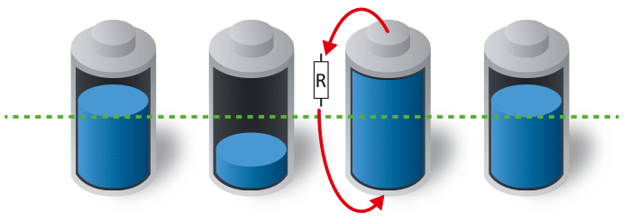
BMBs contain one power resistor and Field Effect Transistor (FET) per brick. The FET enables a resistor to be connected in parallel with the brick, allowing for controlled energy dissipation and balancing of brick charge levels in the HV battery. BMBs only perform this passive balancing and do not charge the least charge bricks (known as active balancing).
 |
|---|
| Each cell on the picture is equivalent to a brick |
| Passive Balancing with Discharge of Most Charge Bricks |
Operationlink
The BMB functions of measuring module voltage and temperature and balancing brick charge levels are critical to operating the HV battery and the vehicle. A BMB not operating as expected can prevent vehicle charging or starting, and may also cause reduced power or graceful power-off with a 30-second warning while driving to pull over before contactors open.
BMBs continuously monitor temperatures and brick voltages during charging, driving, and low-voltage system support. When the vehicle is asleep, the HVC wakes the BMBs every 10 minutes for them to report measurements and ensure brick health.
BMBs will balance the bricks when the HVC enables balancing. The HVC enables brick balancing only when the charge level of bricks has enough charge or voltage difference, and the least charged brick is above a certain threshold.
BMBs don't have embedded advanced micro processing capabilities. Their duty is to sense voltage, temperatures, and be able to put a resistor across a brick for balancing. All the processing happens in the HVC, which requires the measurements provided by the BMBs. To get the data from BMBs to the HVC, there is a daisy chain leaving the HVC, going through all BMBs in series and back into the HVC.
The daisy chain communication is bi-directional. If the daisy chain is cut anywhere, all BMBs can still communicate to the HVC.
Serviceabilitylink
BMBs not serviceable because they are embedded within the platter area, making them inaccessible due to the structural HV battery's bonded top and bottom enclosures.
High Voltage Battery Thermal Managementlink
Specificationslink
The HV battery uses liquid based thermal systems to keep battery cells at their optimized temperature and to control heat generated during conversions between AC/DC and AC/DC power. The thermal systems are split between cooling the Power Conversion System (PCS) and the cells within the cell-arrays.
Power Conversion System Thermal Looplink
The PCS cooling loop consists of:
- Coolant passthrough to connect external coolant lines to the ones going to the PCS inside the HV battery.
- Inlet coolant hose bringing external coolant to the PCS.
- The PCS cooling plate on which electronic components of the PCS are mounted.
- Temperature sensors on the PCS Printed Electrical Circuit Board (PCBA).
- Outlet coolant hose to push the warm coolant back out to the external cooling system.
- Temperature sensor at the coolant inlet into the HV battery.
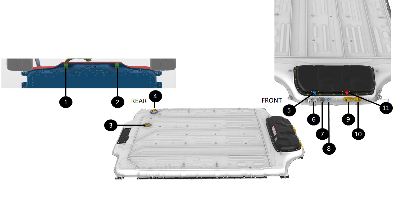
The PCS coolant inlet and outlets are located at the front of the HV battery directly through the ancillary bay cover.
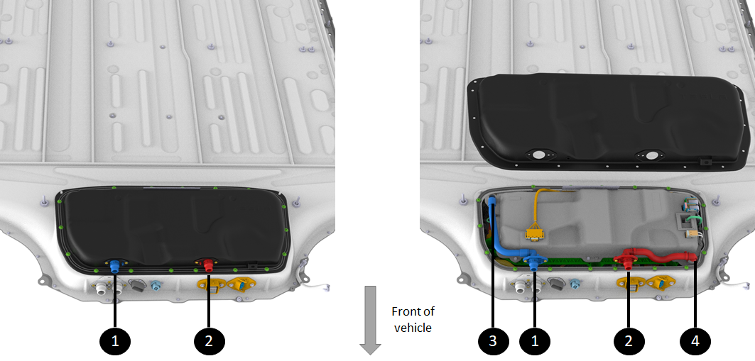 |
|---|
| 1. PCS coolant inlet manifold 2. PCS coolant outlet manifold 3. PCS coolant inlet quick connect 4. PCS coolant outlet quick connect |
| PCS Coolant Loop |
Cell-Array Thermal Looplink
The platter cooling system consists of:
- Coolant passthrough to connect external coolant lines to the ones to the cell-arrays.
- Inlet coolant manifolds to split the coolant flow to all the cooling tubes of the HV battery.
- Cooling tubes thermally connecting the cells to the coolant.
- Outlet manifolds to collect the coolant back from all the cooling tubes .
- Outlet coolant hose to push the coolant back out to the external cooling system.
- Temperature sensors on each BMB.
Operationlink
Power Conversion System Thermal Looplink
The PCS requests a desired temperature to VCFRONT. VCFRONT aggregate all the component temperature requests and appropriately set the pumps speeds and the coolant loop state.
The coolant coming from the PCS inlet passthrough will travel in the PCS cooling plate where heat will be transferred from the PCS electronics to the coolant. The coolant, from the hot electronics, will exit the PCS to get back to the vehicle cooling system where heat will be transferred to the outside air of other components that requested heat.
Cell-Array Thermal Looplink
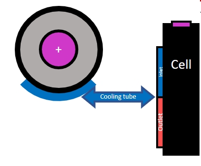
The HVC calculates the desired coolant temperature based on brick State of Charge (SOC), temperatures, and vehicle state, sending it to VCFRONT. VCFRONTaggregates this data to control pump speeds and coolant flow. The output is either hot or cool coolant traveling through the cooling tubes of the platter.
In the cell-arrays, each cell has about a third of its surface in contact with a cooling tube. The entire height of any cell contacts the cooling tube to ensure homogenous temperature along the cell.
Each module has 11 cooling tubes running width-wise.
The cooling tube is split in two height-wise, with the upper side being the inlet and lower side being the return. This circulation allows a more homogeneous heat exchange compared to a series pattern.
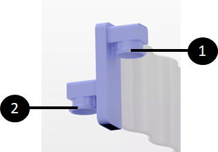 |
|---|
| 1. Input cooling connector 2. Output cooling connector 3. Separator splitting coolant flow in cooling tube |
| Module Cooling Tube Manifold |
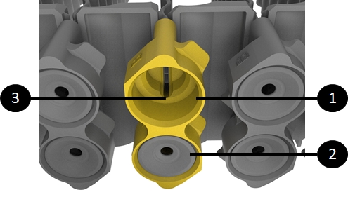
The diagram below shows a top and section view of this cooling tube against a cell. The diagram shows the cooling tube hugging the cell and the section shows the split within the cooling tube between inlet and outlet.
 |
|---|
| Split Cooling Tube Hugging the Cell |
As shown on the picture below, the cooling tube manifold splits the inlet and outlet for the module cooling tube.
 |
|---|
| 1. Input cooling connector 2. Output cooling connector 3. Separator splitting coolant flow in cooling tube |
| Cooling Tube Manifold |
Coolant flows in a "U" shape inside each coolant tube, with the inlet and outlet on the same end of the module. This is shown with the red and blue arrows in the picture below.
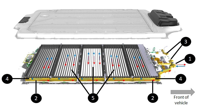 |
|---|
| 1. HV battery coolant manifold for module cooling loop 2. Return hose 3. Ancillary Bay or power conversion system (PCS) coolant manifold 4. Input coolant line to modules 5. Module dual direction cooling tubes |
| Platter / Module / Cell Cooling Flow |
Serviceabilitylink
Overpressure / Overtemperature Dissipationlink
Specificationslink
The HV battery needs to be able to handle thermal runaway events internal to the HV battery in a controlled manner. Those events are sometimes caused by:
- Significant external damage to the HV battery causing cell penetration or deformation
- An internal coolant or other liquid flood. In rare cases, it can also be caused by some internal failures in the HV battery.
The HV battery features the following hardware to control runaways:
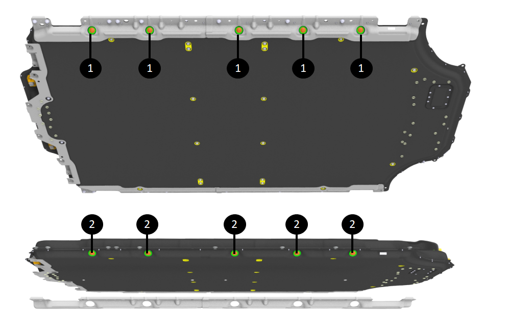
- Pack venting to allow controlled release of internal HV battery overpressure. The HV battery uses umbrella valves to allow the pressure in the enclosure to vent if pressure builds up inside the HV battery.
The valves in Model S and X (2021+) HV batteries are similar to earlier models, but with fewer valves required due to the 5-module and 5-module bay configuration. The valves are located on the long side of the battery (passenger side for LHD vehicles) and point downward at a small angle.
The position of the umbrella valves and their integration in the Model S and X (2021+) HV battery prevents dirt and debris accumulation.
 |
|---|
| 1. Umbrella valve assembly at 5 module bays 2. Umbrella valve assembly at 5 module bays without side ski (ski NOT removable in service - picture just for visual) |
| Vent locations |
The umbrella valves of the Model S and X (2021+) HV battery are spread in a single pattern, one per module bay. They are mounted individually on a small carrier, rather than on a shared carrier, like the Gen 2 pack.
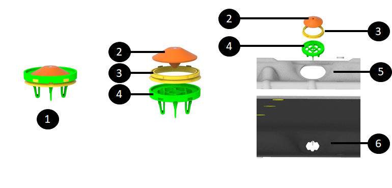
Each vent assembly is made of:
- A valve carrier that snaps into the assembly from the outside
- A valve that is press fitted into the valve carrier
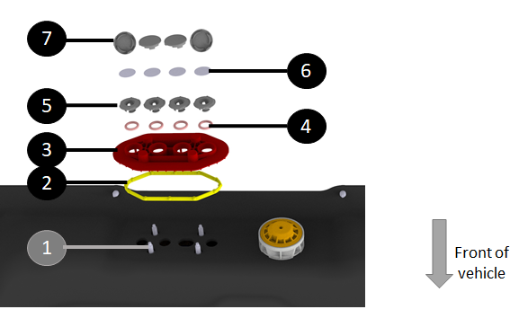
 |
|---|
| 1. Umbrella valve assembly 2. Rubber snap in - one-way valve 3. Support ring 4. Umbrella valve carrier 5. Opening in ski big enough for entire umbrella valve assembly 6. Opening in enclosure for entire assembly to let pressure out through umbrella valves |
| Vent assembly |
The enclosure is sealed from the outside, meaning that no water can get in. However, the enclosure needs to be able to equalize pressure with the outside. Temperature and elevation changes can cause the pressure outside to change, and the enclosure needs to equalize its internal pressure with the outside to prevent internal under-pressure or over-pressure that would stress components and could cause leaks. To achieve pressure balance, the Model S and X (2021+) HV battery has 4 two-way breather valves in the rear, next to the flood port.
 |
|---|
| 1. Breather assembly with 4 breathers |
| Breather location |
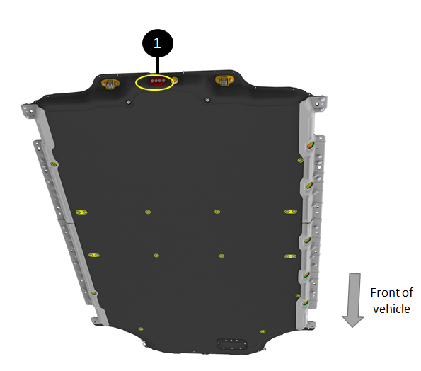
- Flood ports to allow automated drainage of any liquids trapped in the HV battery. Flood ports open when liquid contacts the inside of the flood port on the HV battery side (and not when liquid contacts the section of the flood port sticking outside of the HV battery).
The Model S and X (2021+) HV battery has a single flood port located in the rear, next to the breathers.
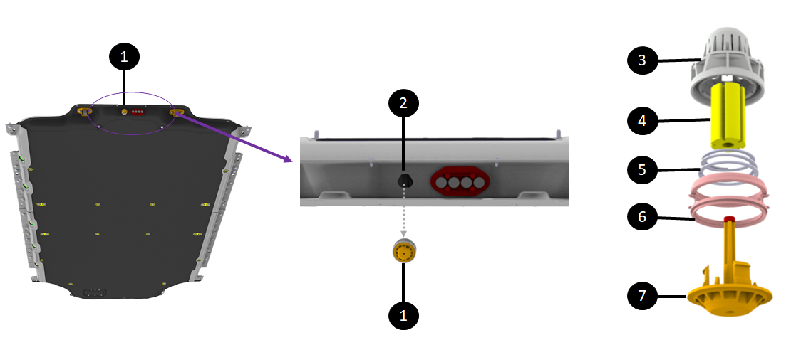 |
|---|
| 1. Flood port on rear flange of HV battery enclosure 2. Opening in enclosure for flood port where liquid will exit when flood port opens 3. Flood port basket housing preventing blockage 4. Cellulose element 5. Spring load allowing the valve to shoot down when cellulose element dissolves 6. Flood port carrier 7. Valve pushed down in presence of liquid |
| Flood port location and assembly |
The cellulose-based ring is not serviceable. Once the flood port has been opened, it needs to be replaced. The flood port is replaceable in service from the outside of the HV battery. It can be rotated out while pulling. It is likely that a plastic tab will break and fall into the HV battery, which is OK.
Operationlink
Pack Ventslink
If pressure builds up inside the HV battery, the umbrella valves are designed to open outward, allowing pressure to escape the enclosure if it builds up inside. It is a one-way valve, designed so that air or other environmental debris will not enter the HV battery. The umbrella valve will disintegrate under high heat. Once disintegrated, it creates a large opening to allow faster expulsion of high-pressure gases inside the HV battery.
Flood Portslink
Any long standing liquid inside the HV battery is concerning, it could overtime create soft short between cells that could generate uncontrolled heat. Flood ports automatically drain any liquid inside the HV battery to below modules. A flood port is a mechanical one way valve that opens in presence of liquid. It has a cellulose element that expands upon contact with liquid. This causes a plastic retainer to release a spring that opens the valve to let the liquid drain from the Ancillary Bay . The flood port design helps:
- Prevent hazardous pooling of fluid inside the HV battery volume.
- Seal against liquid/gas passage into the HV battery from outside.
The flood port is one time use, once it opens, it cannot close back and needs to be replaced. However, the flood ports are replaceable in service from the outside of the HV battery by twisting and pulling. It is likely that a plastic tab will break and fall into the HV battery, which is okay.
The breathers are all mounted on the same carrier. The breather valve equalizes the pressure between the inside of the HV battery and the outside environment under normal operation. It is designed to handle a vehicle driving up any hill.
The umbrella valves mentioned in the HV battery venting section handle high level over-pressure inside the HV battery. They are one-way valves, only releasing pressure from inside the enclosure to the outside. The 4 breather valves are two-way valves.
 |
|---|
| 1. Fastener to breather assembly (from inside HV battery - not accessible for service) 2. Breather assembly seal 3. Breather assembly plate 4. Breather seals 5. Breather mount 6. Breather valve 7. Breather cap |
| Breather assembly, "exploded" view |
Serviceabilitylink
Both vents and flood ports are replaceable in service if damaged, missing or opened. They snap on to the enclosure from the outside of the HV battery (flood port require a twist before being pulled out)
Note
If it is suspected that a HV battery has liquid in the platter, service is responsible for draining the liquid as soon as possible.