Cybertruck Thermal Managementlink
Last updated: November 05, 2024
Vehicle Thermal Systemlink
Heat Pump Basicslink
A heat pump transfers energy from a low temperature level to a higher temperature level using refrigerant as the energy transfer medium. Similar to an air conditioning system, a heat pump uses the following 4 stages of the basic refrigerant cycle:
- Compression via Compressor
- Heat Rejection via Condenser
- Expansion via Expansion Valve
- Heat Absorption via Evaporator
A heat pump uses a compressor to compress the refrigerant to a higher pressure / temperature and then circulate it to the condenser where it condenses and releases heat. Refrigerant then drops in pressure / temperature through the expansion valve (EXV) before vaporizing by absorbing heat in the evaporator. The refrigerant then returns back to the compressor to repeat the cycle.
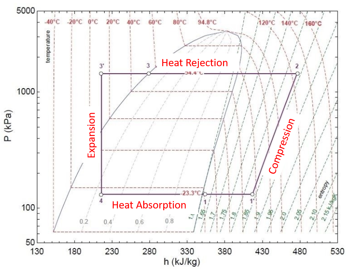
Shown below is a detailed description of the refrigerant cycle and the related 4 stages:
 |
|---|
| Refrigerant Cycle Diagram |
-
Compression Phase: (1 ➔ 2)
- The AC compressor compresses the refrigerant, resulting in an increased pressure and temperature.
- The refrigerant is in 100% vapor state during the entire compression stage.
-
Heat Rejection Phase: (2 ➔ 3 ➔ 3)
- In the condenser(s), heat is rejected and refrigerant temperature decreases while the pressure remains high.
- When starting to cool the refrigerant (starting at point 2 in the diagram), it is in 100% vapor state until it reaches the parabolic-shaped area (between points 2 and 3 following the 54.4 °C dotted temperature line).
- The area to the right of this line is the vapor area.
- From this point going to the left of the diagram, the refrigerant condenses to 100% liquid until point 3 has been reached.
- In the area to the left of point 3, the refrigerant is in 100% liquid state.
- The coexistence area lies within the parabolic shape.
- The refrigerant transitions from 100% vapor, going to the left through the coexistence phase (=gas/liquid mixture) at a fixed temperature into 100% liquid state.
- Normally, refrigerant always transitions from vapor to liquid (and vice versa) when going through the area of coexistence.
- There is only one exception, which is the 94.8°C temperature line touching the top of the coexistence area. Under this combination of pressure and temperature, refrigerant transitions from 100% vapor into 100% liquid all at once. This is the refrigerant's critical point.
- When refrigerant is in its coexistence phase, the temperature does not change due to physical characteristics. Temperature only changes if refrigerant is in 100% vapor state or 100% liquid state.
- Specifically in the 3 ➔ 3 portion, the condenser(s) cool down refrigerant past the point of 100% liquid phase. This temperature drop is the subcool temperature and represents the overcapacity of the condenser(s) needed to make sure that refrigerant passes the 100% liquid phase point.
-
Expansion Phase (3 ➔ 4)
- While passing through the expansion valve (EXV), refrigerant drops in pressure and temperature when expanding and transitions from 100% liquid into vapor / liquid mixture (coexistence).
-
Heat Absorption Phase (4 ➔ 1 ➔ 1)
- In the evaporator, heat is absorbed by the refrigerant and cools the cabin air when it flows through the cabin’s evaporator.
- In the coexistence phase (point 4 ➔ 1), heat is absorbed at a constant temperature until the 100% gas phase has been reached (point 1).
-
Evaporation Phase (1 ➔ 1)
- Evaporator heats up refrigerant past the 100% vapor phase point.
- This temperature increase is the superheat temperature. The superheat temperature represents the overcapacity of the evaporator needed to make sure the refrigerant passes the 100% vapor phase point.
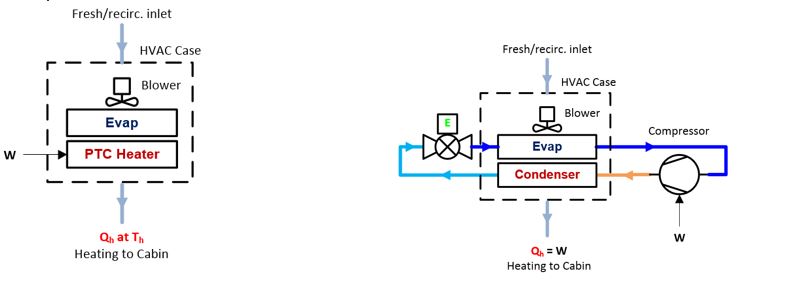
Difference Between Heat Pump and Standard Air Conditioning Systemslink
Unlike a standard air conditioning system, a heat pump can be used for both heating and cooling. Although both heat pumps and air conditioning systems use the same refrigerant cycle as described previously, the heat pump system uses a series of valves to control the direction of refrigerant flow in the system. For example, the Tesla heat pump system is able to heat or cool the vehicle cabin by directing refrigerant flow to either the cabin evaporator or cabin condenser. These valves and refrigerant flow will be described in detail later in the document.
Coefficient of Performance (COP)link
The Tesla heat pump system operates in various modes defined by the Coefficient of Performance (COP). In general, heating performance is measured by COP rather than efficiency. The higher the COP of the system, the greater the heating performance with respect to the energy input.
Note
Efficiency (η) cannot exceed 100% according to its definition (“free” energy may not be added as energy input). This is the reason why COP is used; it is expressed as a dimensionless factor (not as a percentage).
The definition of Coefficient of Performance is COP=Qh/W=(Energy output)/(Energy input). For example, a Positive Temperature Coefficient (PTC) heater has a (theoretical) COP=Qh/W=1. This means, the energy to heat up the cabin (Qh) = energy from the PTC heater (W), supplied by the HV battery.
 |
|---|
| COP Diagram 1 |
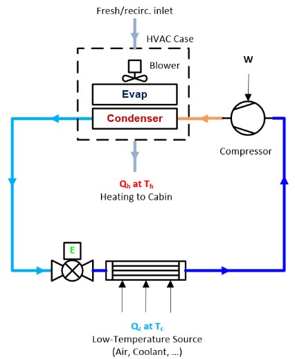
In case of a heat pump (Qh=W+Qc), heat entering the cabin (Qh) equals the electrical energy from the compressor (W) + free energy from the ambient air (Qc), which is why the heat pump is very effective for heating.
A heat pump (COP=Qh/W=(W+Qc)/W≥1), the COP for a heat pump normally varies between 1 and ≈5 depending on ambient temperature. If, for example COP=3, the cabin is heated (Qh) with heat pump electrical power (W) = 100% + Qc (energy for free from ambient air or coolant) = 200%, in total 300% = COP 3.
 |
|---|
| COP Diagram 2 |
Coefficient of Performance (COP) Modeslink
The Tesla heat pump system operates in different COP modes, varying from a very efficient COP ≈ 5.6 to a PTC heater-like efficiency of COP=1. These COP modes are expressed in a range from COP High, COP Blend, and COP 1. The modes change depending on:
- Ambient temperature
- HV battery temperature
- Coolant temperature
- Whether cooling or heating (cabin or HV battery) is requested.
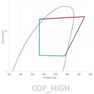
COP High Modelink
The COP High Mode is used when battery temperature is between 15°C to 50°C range (see image below). This is the most efficient and preferred mode the heat pump can run in, COP up to ≈5.6 in best scenario. In this mode, the AC compressor is running at its lowest speed.
 |
|---|
| COP High Mode |
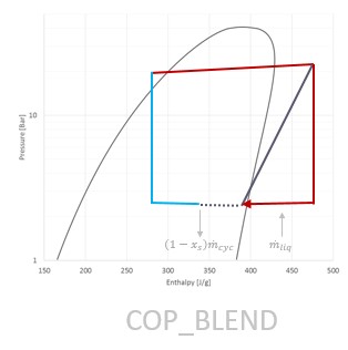
COP Blend Modelink
The COP Blend Mode is used when battery temperature is between +10°C to +15°C range (see image below). The goal is to use a controlled amount of heat from the powertrain / battery to heat the cabin. In COP Blend Mode, the COP value is between ≈5.6 and 1, the refrigerant is under temperature, pressure is entering the mister (see refrigerant loop section), and supplements the chiller heat from the ambient or powertrain / battery with electrical power used by the heat pump.
 |
|---|
| COP Blend Mode |
This operation mode allows the system to act like a conventional heat pump and an electrical heater at the same time. COP Blend Mode is used get a reasonably good COP without over-cooling the battery (e.g., the naturally produced heat from driving around almost funds the cabin heating needs, but not fully).
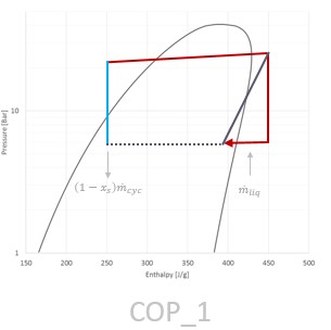
COP 1 Modelink
The COP 1 Mode is used when the battery temperature is between -40°C to +10°C range (see image below). COP 1 Mode is an extreme version of COP Blend Mode, where the heat pump acts as a PTC heater. This mode is the least efficient mode and the heat pump is running at COP = 1.
 |
|---|
| COP 1 Mode |
In COP 1 Mode, the system quickly heats up refrigerant, transferring the electrical power consumed by the compressor to the cabin. When the system is running in COP 1 mode, the compressor is running at high compressor speeds at start up. This requires the EXV.recirc to actuate in such a way (along with the other valves) to regulate the suction and discharge pressures. When there is enough heat in the system, it changes over to COP Blend mode.
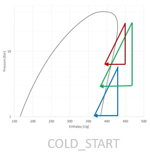
Cold Start Modelink
Cold Start Mode is used in very cold circumstances where neither the ambient air nor the HV battery can provide enough energy (see image below). In this mode, refrigerant is heated up in a similar way as COP 1, but it is flowing through the compressor, EXV.recirc, mister, and accumulator by closing all other expansion valves.
This process is shown in the right side of the image below where the triangles are going from blue to green to red and then going into COP 1 Mode, building up pressure and temperature into the system.
 |
|---|
| Cold Start Mode |
Heat Pump Sourceslink
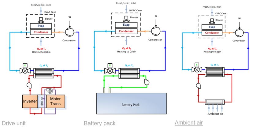
The Tesla heat pump relies on 3 heat sources:
- Drive unit's rejected heat scavenging.
- HV battery thermal mass funding energy.
- Ambient air (through the radiator).
All 3 of these heat sources require heat transfer to the refrigerant using the vehicle coolant loop (see image below).
 |
|---|
| Heat Pump Sources |
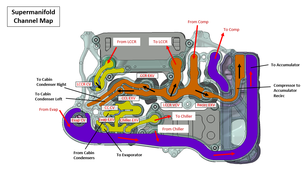
Thermal Schematic Overviewlink
Coolant Looplink
In order to transfer heat between the vehicle coolant loop and refrigerant, the coolant loop needs to be in the correct position.
Note
Cybertruck is available in Dual Motor or Tri Motor configurations. The coolant loop configurations are similar for both, except the Tri Motor configuration has 2 rear drive units connected in parallel with the front drive unit, while the Dual Motor configuration only has 1 rear drive unit connected in series with the front drive unit.
Pictured below is the Tri Motor configuration and the 5 possible positions the coolant loop can be in:
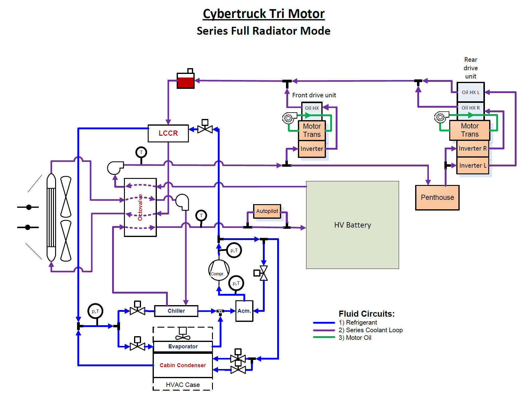
-
Series Mode
- Series Mode connects the HV battery coolant loop to the powertrain coolant loop for heat rejection from both loops via both radiators to ambient (see image below).
-
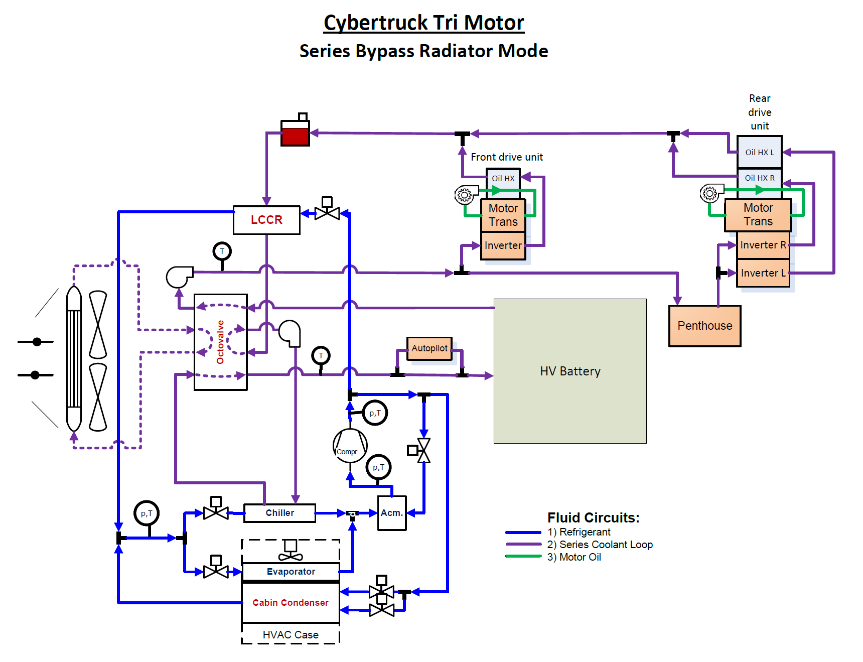
Series – Radiator Bypass Mode
- Series – Radiator Bypass Mode connects the HV battery coolant loop to the powertrain coolant loop for heat rejection from both loops via chiller for heat pump cabin heating (see image below).
-
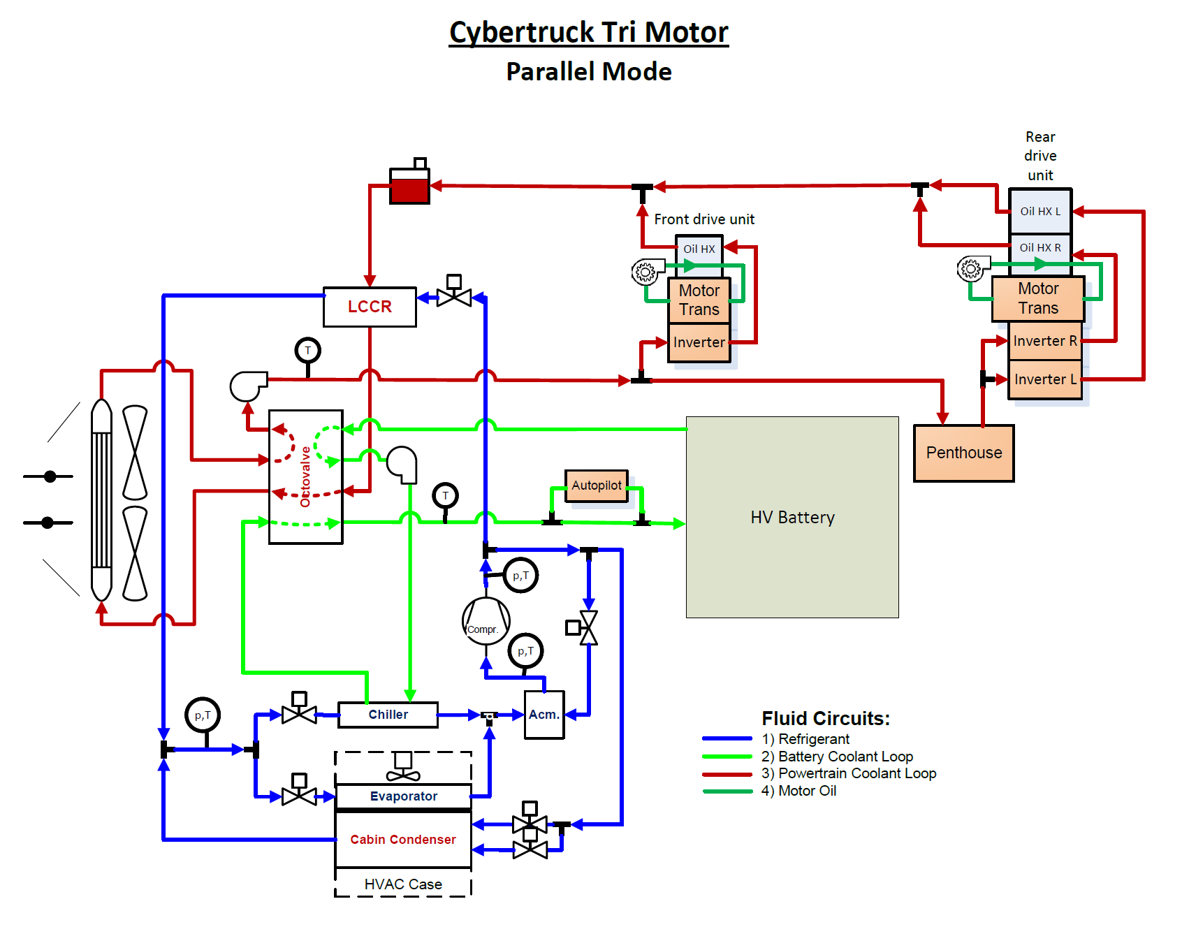
Parallel Mode
- Parallel Mode separates the HV battery and powertrain coolant loops. This mode allows separate heat rejection from HV battery and powertrain to their respective separate radiators.
- Parallel Mode also allows heat rejection from HV battery via chiller for heat pump cabin heating.
-
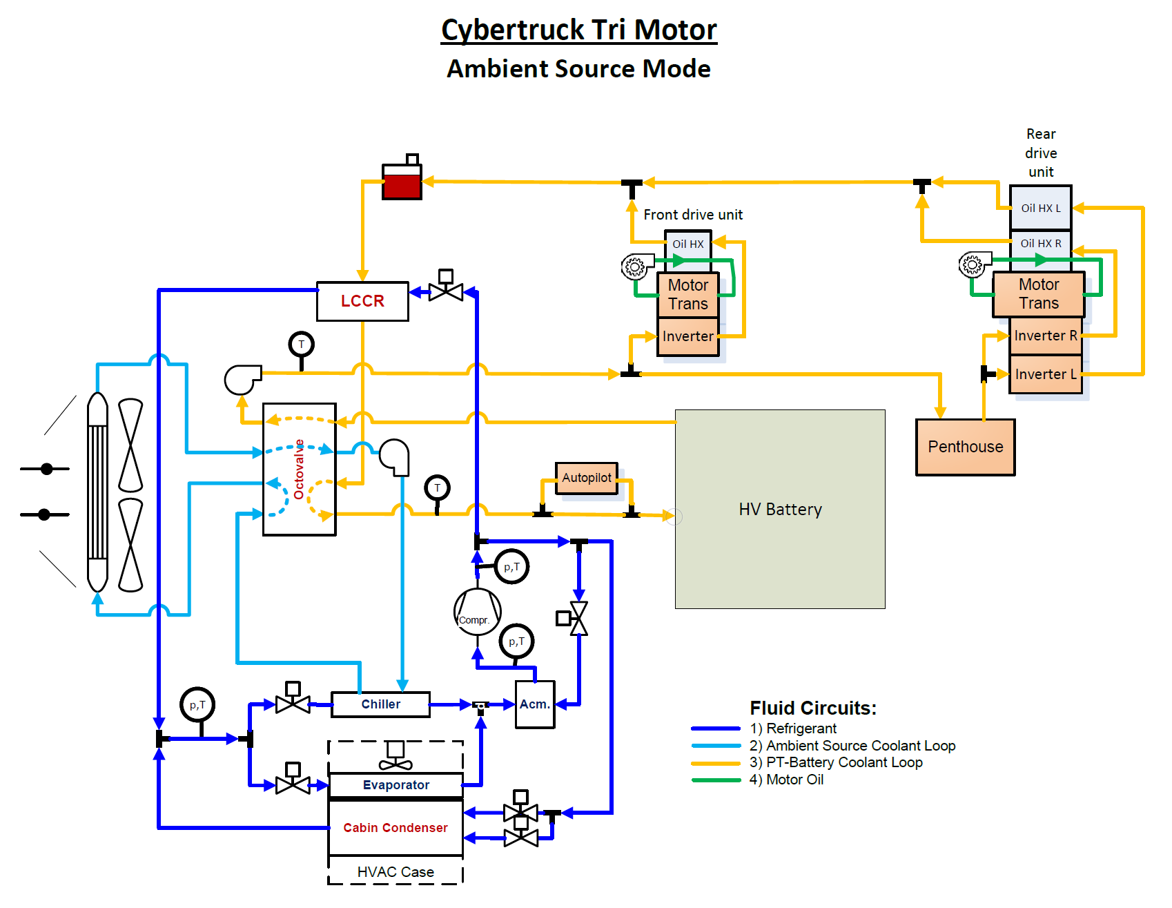
Ambient Source Mode
- Ambient Source Mode allows heat from ambient air via the powertrain radiator to be rejected to the chiller for heat pump cabin heating.
- This mode also connects the HV battery coolant loop to the powertrain coolant loop, bypassing the battery radiator, for HV battery heating.
-
COP 1 Mode
-
COP 1 Mode turns OFF the chiller pump, thus allowing no heat from ambient air via the powertrain radiator to be rejected to the chiller. Instead, the A/C compressor uses the internal mister loop to generate heat for cabin heating.
-
COP 1 Mode also connects the HV battery coolant loop to the powertrain coolant loop, bypassing the battery radiator, for HV battery heating (same as Ambient Source mode).
-
 |
|---|
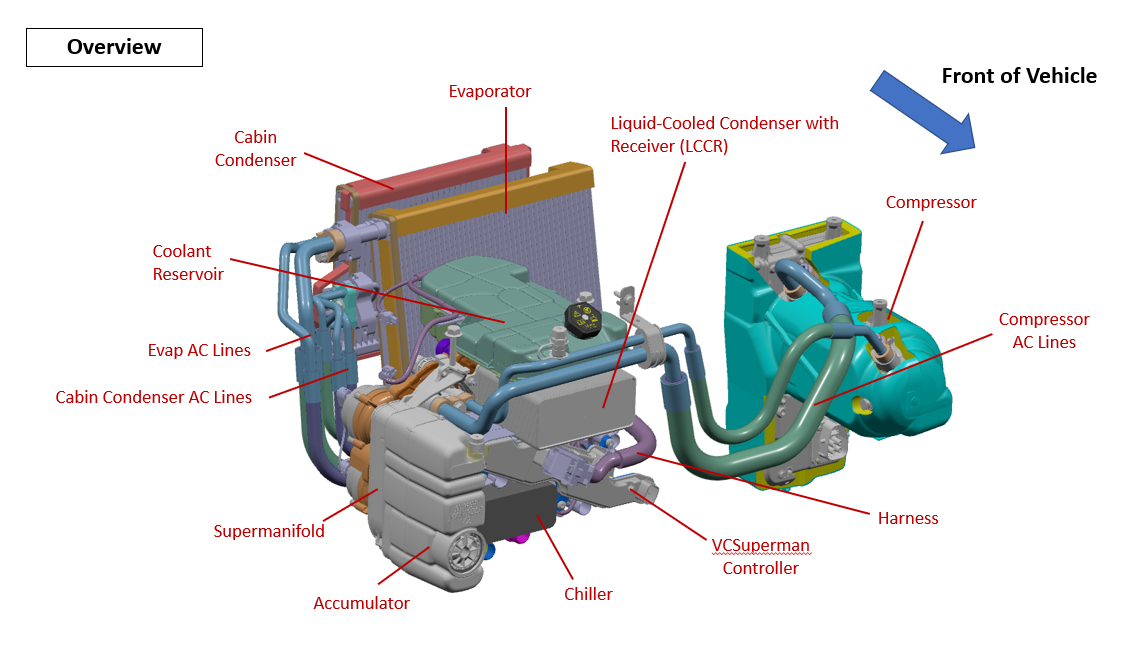
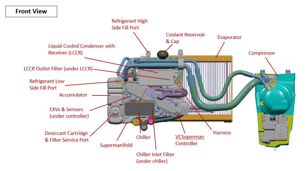
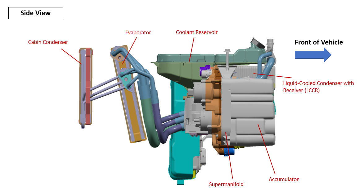
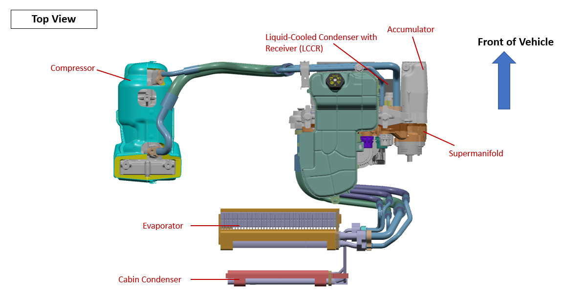
Overview of Heat Pump System Componentslink
The following diagrams show the layout of the Cybertruck heat pump system and the related components. Each component is described in further detail.
 |
|---|
| Heat Pump Overview |
 |
|---|
| Heat Pump (Front View) |
 |
|---|
| Heat Pump (Side View) |
 |
|---|
| Heat Pump (Top View) |
 |
|---|
| Supermanifold (Front View) |
 |
|---|
| Supermanifold's Internal Passages (Back View) |
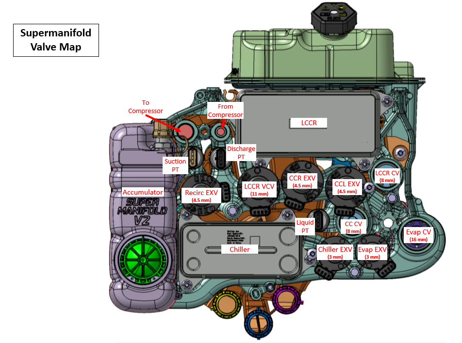
Components, Abbreviations, and Their Functionslink
Liquid Cooled Condenser with Integrated Receiver (LCCR)link
Cybertruck has a Liquid Cooled Condenser with an Integrated Receiver (LCCR). The addition of a receiver to the liquid cooled condenser improves cooling performance by increasing the amount of subcooled refrigerant available. The LCCR rejects heat from refrigerant to coolant and is needed for evaporator cabin cooling, chiller battery cooling, or ambient source battery heating. The LCCR is mounted to the supermanifold.
Cabin Condenser (CC)link
The Cabin Condenser (CC) rejects heat from refrigerant to cabin air. The left and right cabin condensers reject the exact amount of heat needed for split temperature settings by controlled by the left and right cabin condenser electronic expansion valves (EXV.CC_L and EXV.CC_R).
Evaporatorlink
The evaporator pulls heat from the cabin air and rejects this heat to the refrigerant. In particular conditions, the evaporator also runs at the same time as the cabin condensers (heating up cabin air) to control humidity and temperature.
Chillerlink
The chiller pulls heat from the coolant and rejects this heat to the refrigerant for cooling the HV battery, Power Conversion System (PCS), autopilot ECU, and drive units. Likewise, the chiller is also used to scavenge heat from the HV battery and powertrain to efficiently heat the cabin.
Accumulatorlink
The accumulator controls the amount of liquid refrigerant and vapor quality that enters the compressor. It also manages the oil's return to the compressor. The accumulator houses two filters, a desiccant bag, and stores inactive refrigerant charge.
Misterlink
The mister is similar to a venturi principle. It blends vapor refrigerant (coming from the AC compressor when the EXV.recirc is opened) with liquid refrigerant in the accumulator.
Electronic Expansion Valves (EXV)link
In an electronic expansion valve (EXV), refrigerant drops in pressure and temperature when expanding and transitions from 100% liquid into vapor / liquid mixture (coexistence). The supermanifold has 6 expansion valves on it, which are described in the sections below:
-
Chiller Expansion Valve (EXV.chiller):
- The chiller expansion valve (EXV.chiller) controls refrigerant flow to chiller.
- The EXV.chiller is actuated based on signals from the pressure temperature subcool (PT SC) sensor on the liquid pressure line between condensers and EXV.chiller.
-
Evaporator Expansion Valve (EXV.evap):
- The evaporator expansion valve (EXV.evap) controls refrigerant flow to evaporator.
- The EXV.evap is actuated based on signals from the pressure temperature subcool (PT SC) sensor on the liquid pressure line between the condensers and EXV.evap.
-
Recirculation Expansion Valve (EXV.recirc):
- The recirculation expansion valve (EXV.recirc) connects the high side of the refrigeration cycle to the mister and controls heat pump operation in COP Blend and COP 1 operating modes. The EXV.recirc valve controls how the heat pump operates in COP Blend and COP 1 operating states.
- In COP Blend, the goal is to use a controlled amount of heat from the powertrain / battery to heat the cabin. When the EXV.recirc opens, it essentially short circuits the cycle in a controlled way, supplementing chiller heat from ambient or powertrain with electrical power. This blend mode allows the cycle to act like a conventional heat pump and an electrical heater at the same time, depending on the state of the thermal system loop and HVAC needs.
- COP 1 is the extreme version of this mode. In this mode, the compressor is operated “as a heater” and is able to transfer the electrical power consumed by the compressor to the cabin. This requires the EXV.recirc (along with the other valves) to actuate in such a way to regulate the suction and discharge pressures.
-
Vapor Control Valve (EXV.VCV):
- The vapor control valve (EXV.VCV) controls refrigerant flow to the LCCR. The EXV.VCV replaces the LCC EXV and LCC shut off valve (SOV) on previous generations of the supermanifold.
-
Left cabin condenser expansion valve (EXV.CC_L)
- The left cabin condenser expansion valve controls refrigerant flow to the left cabin condenser
- Right cabin condenser expansion valve (EXV.CC_R)
- The right cabin condenser expansion valve controls refrigerant flow to the right cabin condenser
Check Valveslink
All of the check valves are mechanically operated and are described below:
-
Cabin Condenser Check Valve (CV.CC):
- The cabin condenser check (CV.CC) valve prevents refrigerant from entering heat exchangers when it is off.
- This valve stops hot refrigerant from entering the cabin condensers (and thus heating it) when all the high side energy should be rejected to ambient.
-
Liquid Cooled Condenser Check Valve (CV.LCC):
- The liquid cooled condenser check valve (CV.LCC) has the same functionality as CV.CC.
- In addition, it helps avoid too much refrigerant charge from being trapped in the LCC when inactive (like cold weather).
-
Evaporator Check Valve (CV.evap):
- The evaporator check valve (CV.evap) prevents refrigerant from entering the evaporator when not in use.
Coolant Hoseslink
There are 12 coolant hose assemblies on the tri-motor variant and 10 coolant hose assemblies on the dual motor variant. The following diagrams show the layout of the coolant hose assemblies and their part numbers.
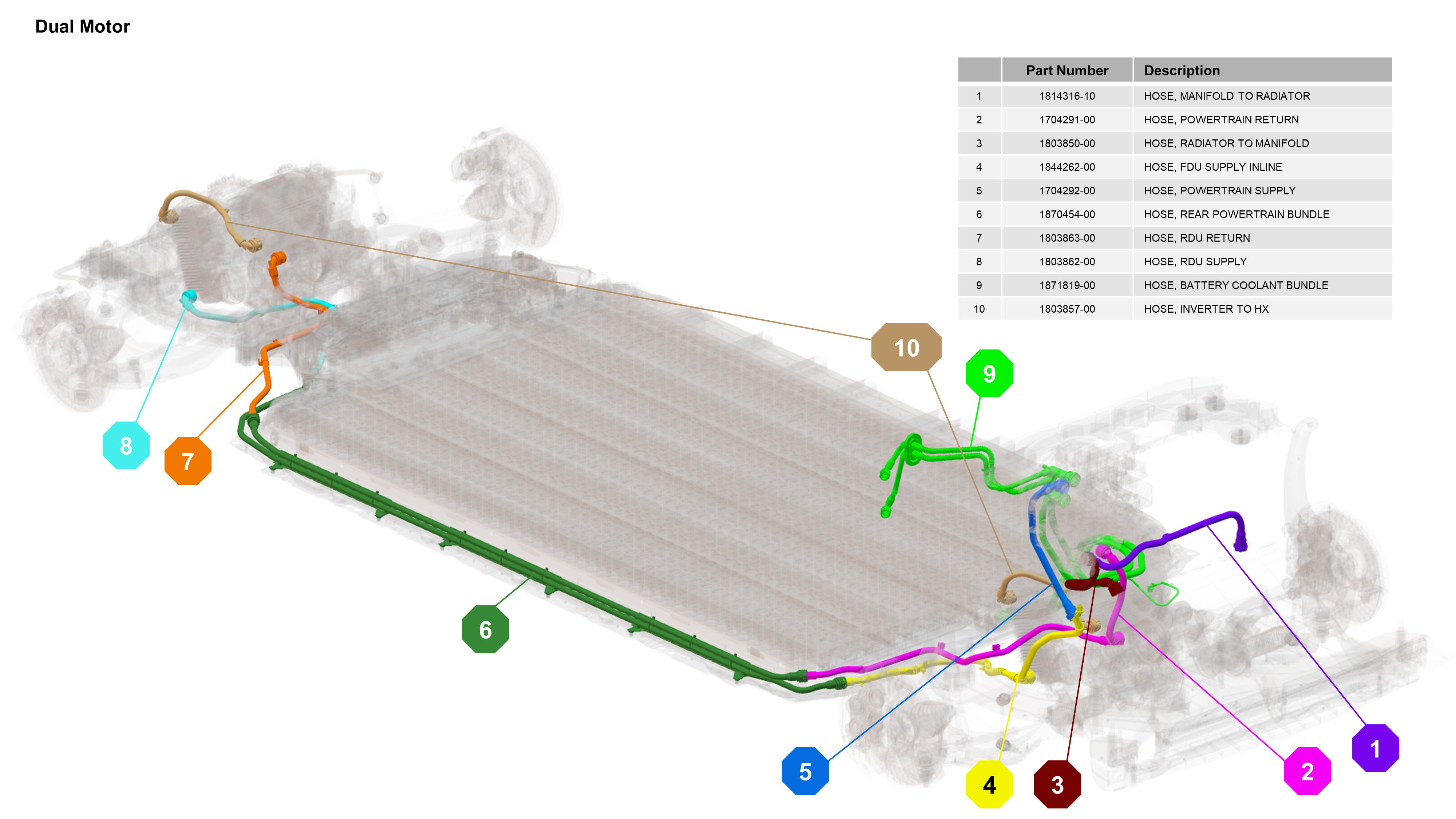 |
|---|
| Dual Motor Coolant Hoses |
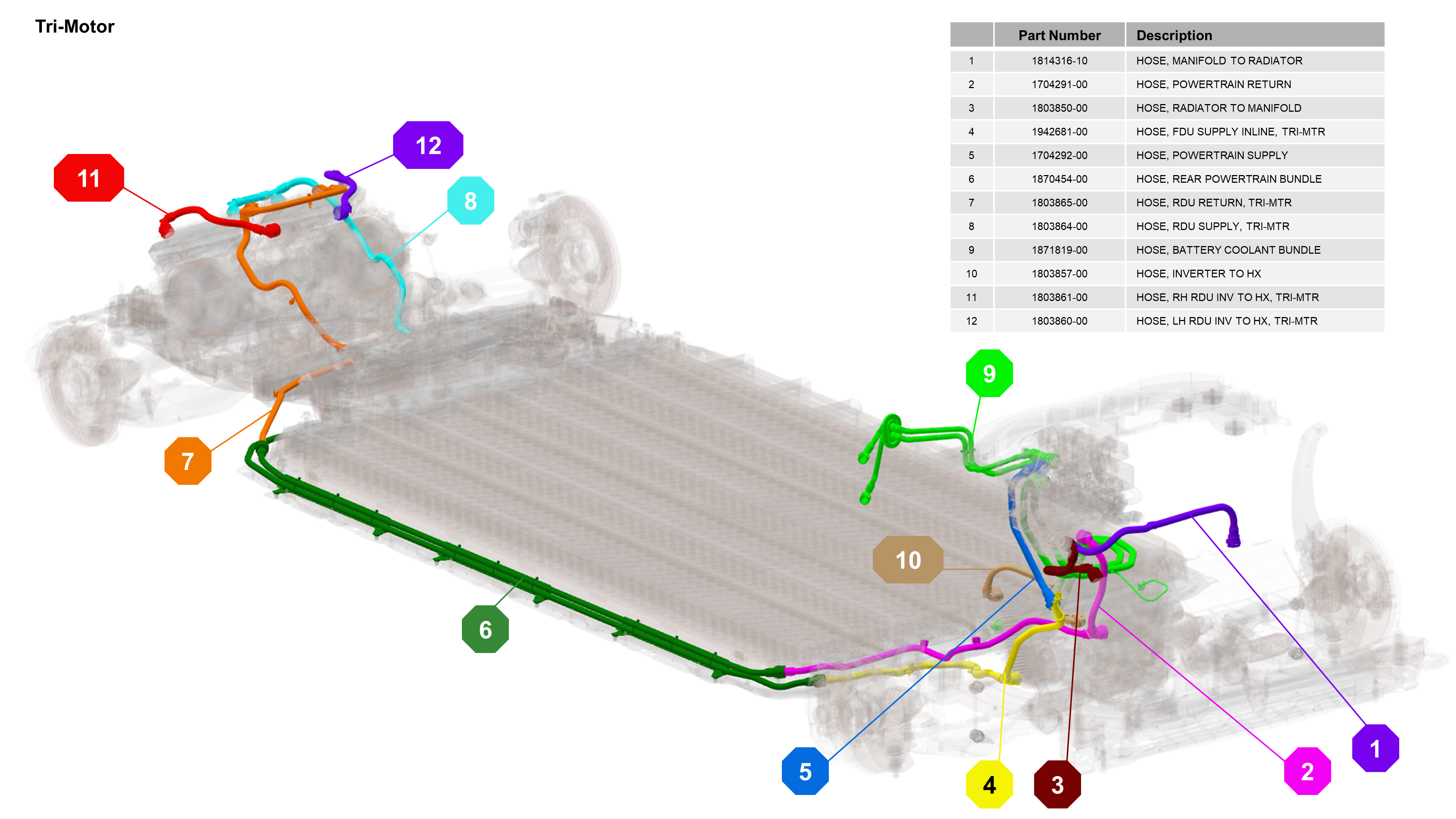 |
|---|
| Tri-Motor Coolant Hoses |
Refrigerant Pressure and Temperature (PT) Sensorslink
All of the refrigerant pressure and temperature (PT) sensors are described below:
-
PT Discharge Sensor:
- The PT discharge sensor (PT high) measures the refrigerant discharge pressure and temperature.
- It is the true A/C compressor discharge and protects the compressor from over-pressure/over-temperature.
-
PT Liquid Sensor:
- The PT liquid sensor measures the subcool of the refrigerant leaving the LCCR and entering the chiller and evaporator.
- This sensor is used to control the cycle, thus providing adequate subcooled liquid refrigerant to the chiller and evaporator for maximum cooling.
-
PT Suction Sensor (PT Low):
- The PT suction sensor (PT low) measures the refrigerant suction pressure and temperature.
- It is used for COP 1 and detecting abnormal conditions/low refrigerant charge.
Refrigerant Filterslink
The Cybertruck supermanifold has 3 refrigerant filters. All 3 filters are serviceable and can be removed to check for debris inside the refrigerant system.
- Desiccant Filter: Located in the accumulator under the desiccant cartridge. Remove the desiccant cartridge to access the filter.
- LCCR Filter: Located in the LCCR outlet port. Remove the LCCR to access the filter.
- Chiller Filter: Located in the chiller inlet port. Remove the chiller to access the filter.
Thermal System Operationlink
Most Common Modeslink
The most common modes (out of 30 possible modes in total) are shown below.
HVAC Pure Coolinglink
When air humidity is in its correct range, reheating is not needed and only the evaporator is used to condition the cabin air. The compressor, liquid cooled condenser receiver (LCCR), and evaporator are in use at the refrigerant side. Refrigerant heat is rejected in the LCCR and heats up the coolant to heat the HV battery when in Series or rejects heat through the radiator when in Parallel.
In these circumstances, usually ambient temperature is high enough for the refrigerant cycle to run in COP_high mode, so the system is running in the highest efficient mode.
HVAC Pure Cooling + Supercharginglink
Same situation for the cabin cooling applies here: when the air humidity is in its correct range, reheating is not needed and only the evaporator is used to condition the cabin air.
In the situation where the HV battery needs cooling as well, the compressor, liquid cooled condenser receiver(LCCR), evaporator, and the chiller are in use at the refrigerant side. Refrigerant heat is rejected in the LCCR, heats up the coolant, and rejects that heat through the radiator. In this mode, the system runs in Parallel.
In these circumstances, usually ambient temperature is high enough for the refrigerant cycle to run in COP_high mode, so the system is running in the highest efficient mode.
HVAC Pure Heating + Scavengelink
During pure cabin heating, only the cabin condensers are used to heat up the cabin air. At the refrigerant side, the compressor, cabin condensers, and chiller are in use. Refrigerant heat is rejected in both cabin condensers and the HV battery thermal mass is being used (Scavenge) to transfer energy into the refrigerant circuit through the chiller.
Ambient temperatures are low and sufficient to heat up the system, therefore it is running in Series and the radiator is bypassed. The system is able to run in COP_high due in these conditions.
HVAC Pure Heating + COP 1link
During pure cabin heating, only the cabin condensers are used to heat up the cabin air. At the refrigerant side, the compressor, cabin condensers, and mister are in use. The radiator pump is switched off, so there is no heat exchange with ambient air despite the Octovalve being in the Ambient Source position.
The compressor is being shorted by the mister, mixing high temperature and high pressure from the compressor itself with low pressure and low temperature coming from the chiller. This results in an increased suction temperature and pressure. This process runs in COP 1 and basically runs like a PTC heater, turning all electric power into heating refrigerant fast.
Refrigerant heat is rejected in both cabin condensers. Ambient temperatures are low, so the system is running in COP 1 mode to quickly heat up the refrigerant.
HVAC Pure Heating + Heat Battery + Ambient Sourcelink
Cabin condensers are used to heat up the cabin air and at HV battery side, the liquid cooled condenser receiver (LCCR) is used to heat up the coolant flow running through the battery. The coolant running through the chiller is heated up by the radiator coolant flow and is getting its energy from Ambient.
Heat Battery + Ambient Sourcelink
The HV battery is heated by the liquid cooled condenser receiver (LCCR). The coolant running through the chiller is heated up by the radiator coolant flow and is getting its energy from Ambient. Radiator and chiller are in series.
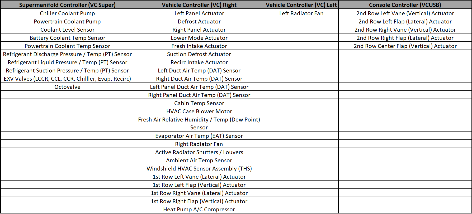
Component Communication and Controllink
The table below outlines the component communication for the supermanifold, Right Vehicle Controller (VCRIGHT), Left Vehicle Controller, (VCLEFT), and the Console Controller.
 |
|---|
Coolant Propertieslink
The coolant fill for Cybertruck consists of G-48 coolant, which is tinted blue. The coolant is supplied from the manufacturer pre-mixed 50/50 concentration with distilled water. G-48 is a long-life coolant designed for high aluminum content powertrain systems.
Warning
Do not top off or refill the cooling system with any other type of coolant.
Coolant Pumpslink
Cybertruck uses two coolant pumps. Both pumps are integrated into the supermanifold and the pumps are serviceable items. The coolant pumps for Cybertruck are a new short body design. They are 6-pole brushless centrifugal pumps designed to run between 45 and 50VDC. They are 3-phase pumps that consume up to 3.7A each when running a maximum duty cycle and 48V nominal voltage. The pumps do not have a built-in controller / driver, and instead, they rely on a controller chip in the supermanifold vehicle controller (VCSuper) to drive the three phases of the pumps.
Coolant Temperature Sensorslink
Cybertruck uses two coolant temperature sensors. The battery coolant inlet sensor provides the HV battery inlet coolant temperature and the powertrain inlet sensor provides powertrain inlet coolant temperature to the supermanifold vehicle controller (VCSuper). Both of these coolant temperature sensors are the same Negative Temperature Coefficient (NTC) sensors and are serviceable items.
Active Shutterslink
Cybertruck has an active shutter assembly that controls airflow to the cooling module. The shutter assembly is visible from the front of the vehicle. The active shutters are motor-actuated from a single actuator and the motor is controlled by the VCRIGHT.
The active shutters control the flow of ambient air through the radiator. The system is designed to keep airflow at the minimum amount necessary for cooling. Also, minimizing the airflow can be used to reduce the time for components to reach normal operating temperature.
The active shutters also minimize the vehicle’s aerodynamic drag when cooling demands are low, thus reducing the vehicle’s power requirements and increasing range. The active shutters close when the vehicle is not in Drive mode, but open if required when cooling the vehicle’s charging system during Charge mode or running the cabin HVAC in Support mode.
 |
|---|
| Active Shutter |
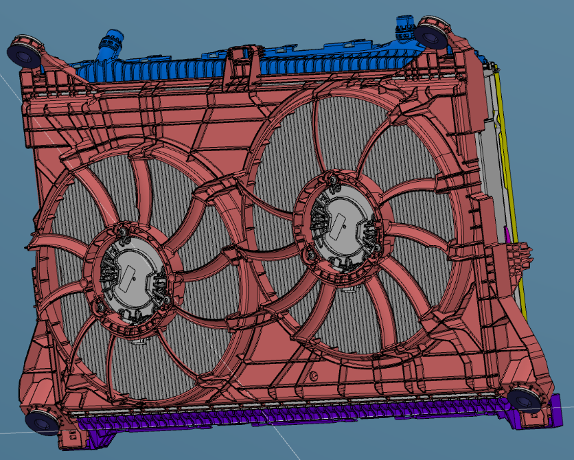
Cooling Fan Modulelink
Cybertruck cooling fan module includes a radiator with a dual radiator fan assembly (see image below). The fan motors are maintenance-free, 3-phase motors. The right fans are controlled by VCRIGHT and the left fan is controlled by VCLEFT. The motors, fans, and shroud are serviced as a single assembly. The radiator can be serviced separately.
 |
|---|
| Cooling Fan Module |
Cabin Heating, Ventilation, Air Conditioning (HVAC) Systemlink
Refrigerant Systemlink
The refrigerant system is a sealed, closed-loop system filled with a refrigerant charge of R-1234yf refrigerant as the heat transfer medium. A non-conductive Polyolefin Ester Oil (POE) with RB100EV specifications is added to the refrigerant to lubricate the internal components of the compressor. This oil is supplied in the compressor during manufacture. Whenever the system is discharged and/or components are replaced, refrigerant and oil must be replaced in an equivalent weight to what was removed.
Note
Specifications and capacities section for refrigerant and oil information table (refer to Appendix A).
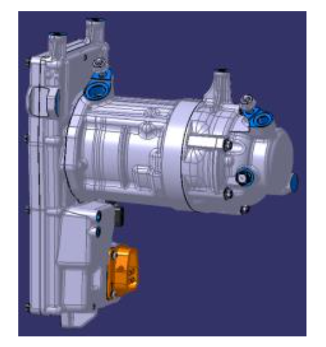
Heat Pump - A/C Compressorlink
Cybertruck has a 1kV heat pump A/C compressor (see image below). It is a high voltage (HV) electric scroll type pump with a maximum rotational speed of 11,000 RPM. The electric A/C compressor pumps refrigerant through the system. The compressor receives the low pressure, low temperature gas which it compresses into high pressure, high temperature vapor. The compressor is mounted under the hood, behind the front trunk.
The compressor has two connectors: one for low voltage and one for high voltage. The compressor operates in any normal range of HV Battery SOC.
 |
|---|
| A/C Compressor |
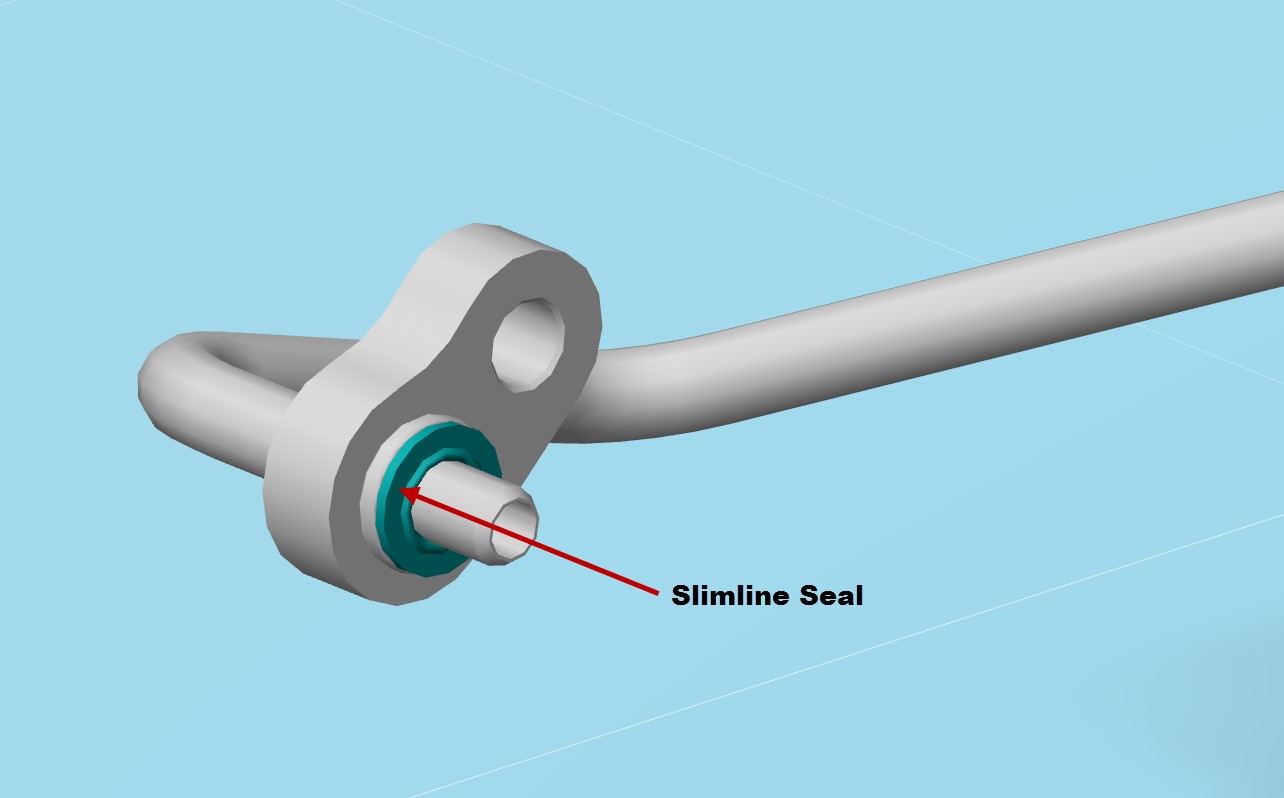
A/C Line Connection Sealslink
All A/C line connection use Slimline style seals, which are only designed for one time use. If the connection is opened, the Slimline seal should be replaced. Cybertruck uses three different sizes of Slimline seals throughout the A/C system.
 |
|---|
| A/C Line Connection Seal |
In-Car Temperature Sensorlink
On Cybertruck, the in-car temperature sensor is located under the front center touchscreen. The sensor is single printed circuit board (PCB) unit, and it has an integrated fan to move air past the sensor for more accurate sensor readings. The sensor communicates to the VCRIGHT.
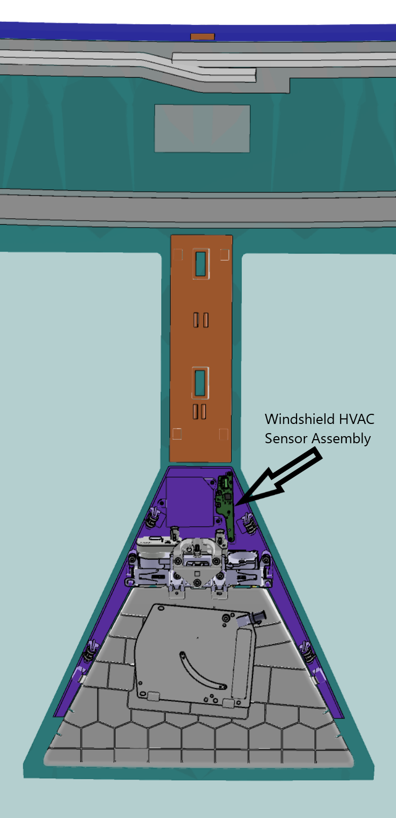
Windshield HVAC Sensor Assembly (Windshield Temperature, Humidity, Sunload)link
The windshield HVAC sensor assembly includes the windshield temperature sensor, humidity sensor, and sunload sensor. All the sensors are contained on one circuit board that is mounted to the windshield surrounding the rear view mirror. The sensors communicate via LIN to the VCRIGHT. The VCRIGHT uses the sunload information to estimate the heating effect on the vehicle from sunlight. It uses this input to maintain the desired cabin temperature as the sunload varies.
The VCRIGHT also uses the humidity data from the humidity sensor for windshield fogging detection. If conditions for windshield fogging are detected, the VCRIGHT attempts to reduce fogging by forcing fresh air, turning on partial Defrost mode, and turning on the air conditioning evaporator.
 |
|---|
| Windshield HVAC Sensor |
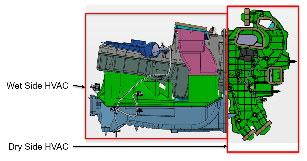
HVAC Caselink
The HVAC case for Cybertruck is unique in that one part of the case is located under the instrument panel (dry side) and the other part of the case is located under the frunk hood (wet side). The components on the wet side versus the dry side of the HVAC case are shown in the image below:
 |
|---|
| HVAC Case |
The HVAC system controls the temperature, humidity, flow volume, distribution, and quality of air within the vehicle to achieve and maintain the conditions requested by the occupants.
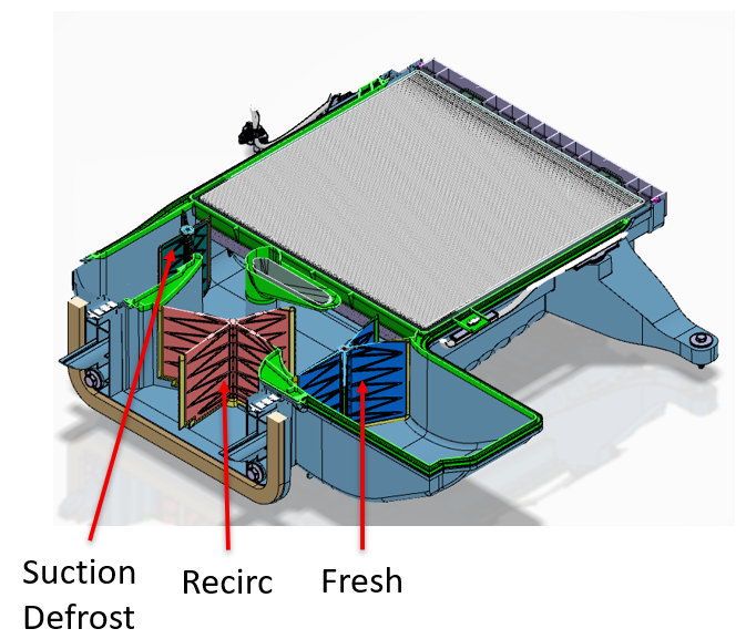
In Fresh Air mode, outside air enters in the underhood frunk area and is pulled into a HEPA filter. In Recirc Air mode, the cabin air enters the HVAC case and is pulled through the same HEPA filter. The Inlet Actuator controls the position of the Fresh/Recirculated air door allowing full Fresh, full Recirculation, or a blend of both Fresh and Recirculated air into the HVAC case.
Air is drawn into the HVAC case by the integral blower motor located under the center of the instrument panel. The air then flows through the evaporator, followed by the condenser. When the air conditioning is required, the evaporator cools and dehumidifies the air. When heating is required, the condenser heats the air.
All the actuators are motor-controlled and have linear potentiometer output based on HVAC door position. The actuator motors operate on 12+ VDC, with an internal potentiometer which uses 5 VDC reference and 0 VDC to 5 VDC potentiometer feedback.
Wet Side of the HVAC Caselink
The components of the wet side of the HVAC case are listed below:
- Blower motor
- Cabin HEPA filter
- Evaporator (cools air)
- Condenser (heats air)
- Actuators (rresh, recirc, suction defrost)
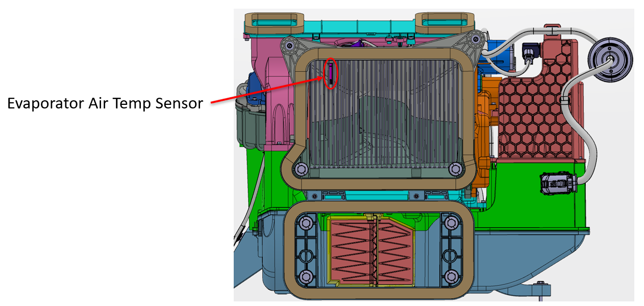
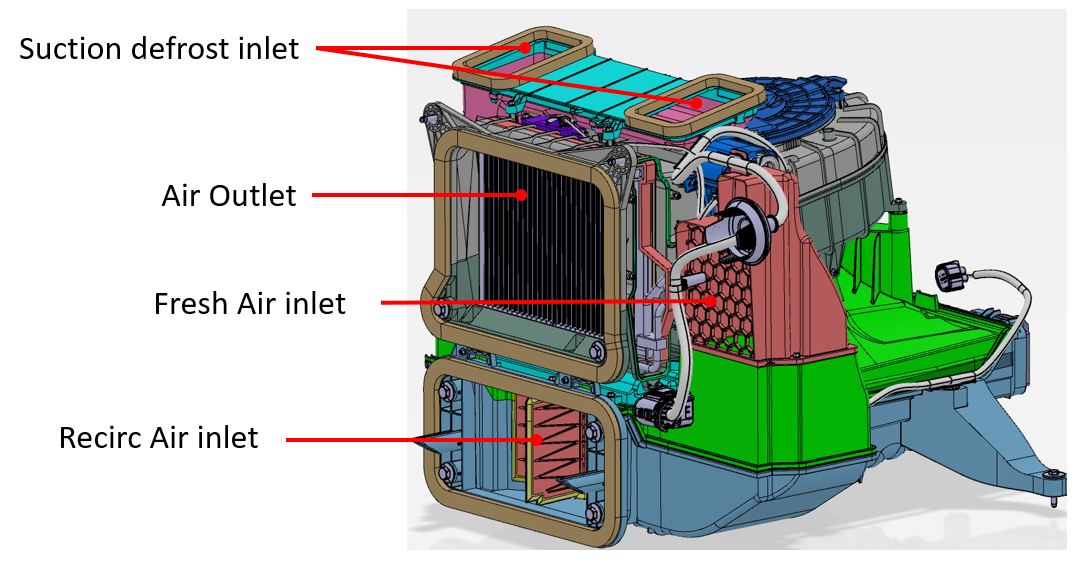
- Evaporator Air Temperature (EAT) Sensor
- Fresh air inlet relative humidity and temperature sensor (new)
- Wet side wiring harness
Dry Sidelink
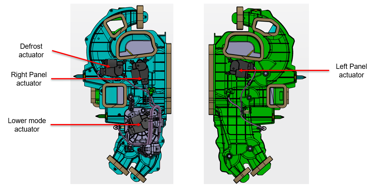
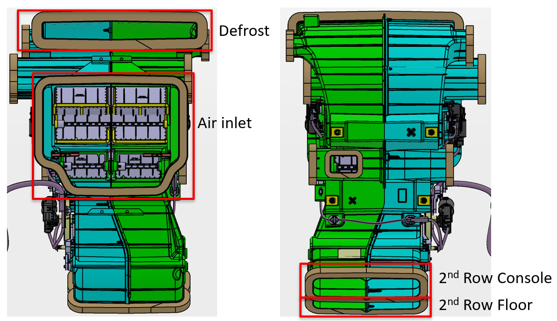
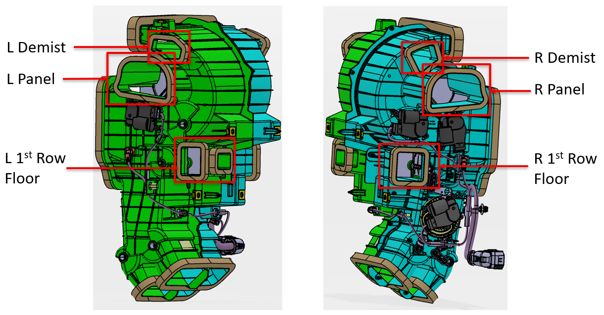
- Duct Air Temperature (DAT) sensors (right panel, left panel)
- Actuators (Defrost, Right Panel, Left Panel, Lower mode)
- Dry side wiring harness
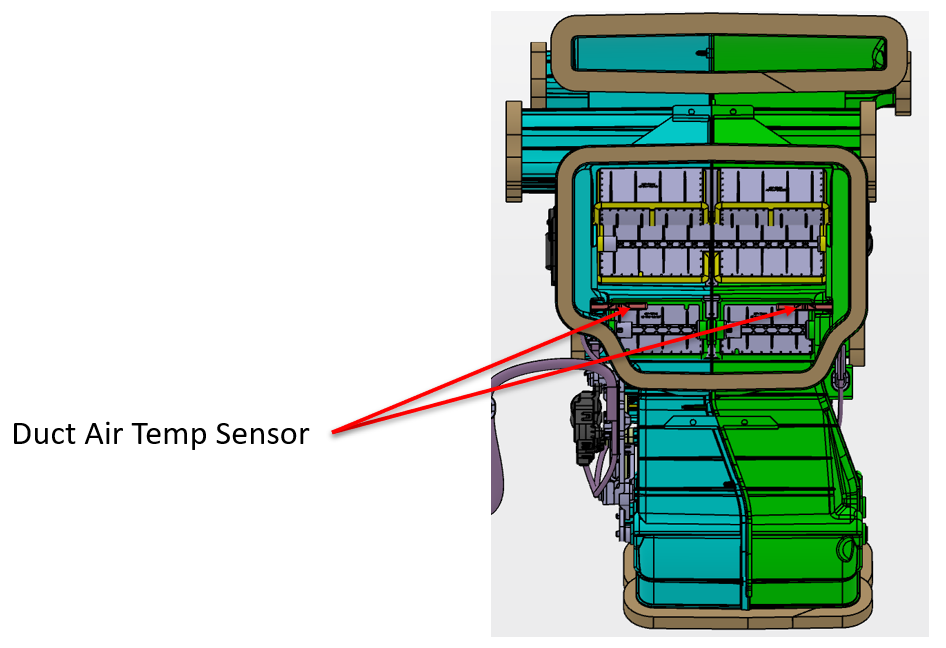
The following DAT sensors are located in the HVAC Ducts, not in the HVAC case:
- Driver Panel
- Passenger Panel
The HVAC system controls the temperature, humidity, flow volume, distribution, and quality of air within the vehicle to achieve and maintain the conditions requested by the occupants.
In Fresh Air mode, outside air enters in the underhood frunk area and is pulled into a HEPA filter. In Recirc Air mode, the cabin air enters the HVAC case and is pulled through the same HEPA filter. The Fresh air actuator, Recirc air actuator, and Suction Defrost actuator work together to control the amount of full Fresh, full Recirculation, or a blend of both Fresh and Recirculated air into the HVAC case.
Air is drawn into the HVAC case by the integral blower motor located in the wet side HVAC case behind the frunk. The air then flows through the evaporator, followed by the condenser. When the air conditioning is required, the evaporator cools and dehumidifies the air. When heating is required, the condenser heats the air.
All the actuators are motor-controlled and have linear potentiometer output based on HVAC door position. The actuator motors operate on 12+ VDC, with an internal potentiometer which uses 3 VDC reference and 0 VDC to 3 VDC potentiometer feedback.
Wet Side HVAC Case - Actuatorslink
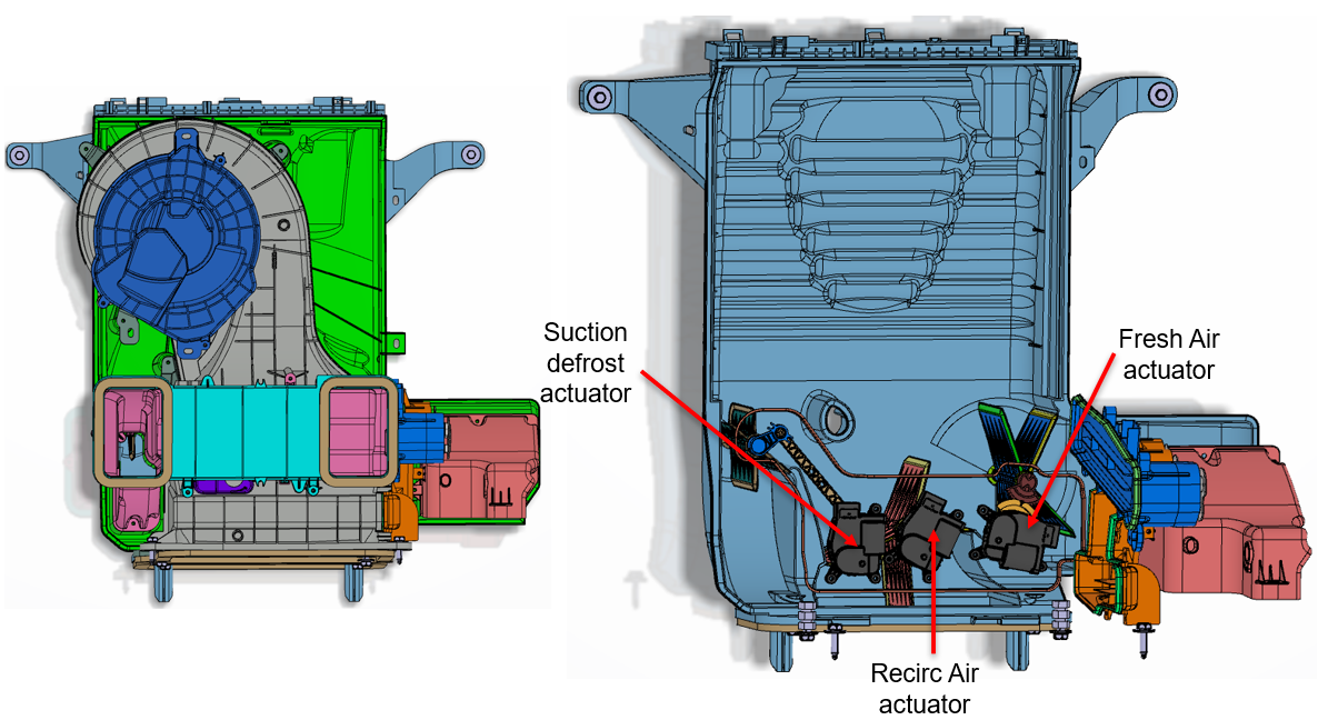 |
|---|
| HVAC Case Actuators (Wet Side) |
 |
|---|
| Evaporator Air Temperature (EAT) Sensor (Wet Side) |
 |
|---|
| HVAC Doors (Wet Side) |
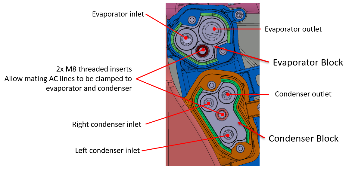 |
|---|
| Heat Exchanger Refrigerant Ports (Wet Side) |
 |
|---|
Wet Side HVAC Case - Fresh Air Relative Humidity / Temperature (Dew Point) Sensor (new)link
New for Cybertruck is a relative humidity / temperature (dew point) sensor located in the fresh air inlet duct. This sensor reduces the heating load on the evaporator in mild ambient temperatures, thus increasing efficiency.
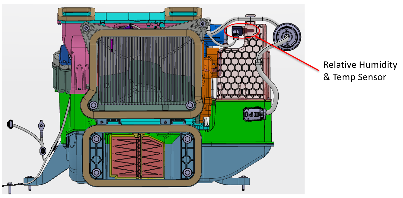 |
|---|
| Fresh Air Relative Humidity and Temperature Sensor (Wet Side) |
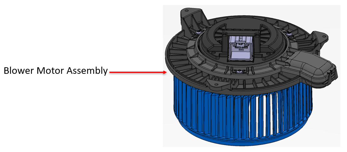
Blower Motor Assembly (Wet Side)link
The blower motor is a maintenance free, 3-phase BrushLess DC (BLDC) motor. The motor speed is controlled by the right vehicle controller (VCRIGHT), which varies the DC voltage (12V battery) to each of the 3-phases in the motor. The motor bearings are pre-lubed for life and the motor is permanently attached to the fan scroll, creating a blower assembly. The blower assembly is serviceable from the HVAC case.
 |
|---|
| Blower Motor Assembly (Wet Side) |
Evaporator (Wet Side)link
The evaporator is integral with the wet side HVAC case. It cannot be removed independently of the HVAC case. High pressure, low temperature refrigerant changes from liquid to vapor as it enters the evaporator and absorbs large quantities of heat as it changes state. As the air passing through the evaporator cools, moisture in the air condenses on the evaporator surface, drying the air that is delivered to the interior of the vehicle. Excess moisture from the evaporator collects in the bottom of the HVAC case and is drained through a port located at the lowest portion of the HVAC case.
Condenser (Wet Side)link
The condenser is integral with the wet side HVAC case. It cannot be removed independently of the HVAC case. High pressure, high temperature refrigerant changes from vapor to liquid as it enters the condenser. During this process, the condenser emits large quantities of heat into the cabin as the refrigerant changes state.
 |
|---|
| Condenser (Wet Side) |
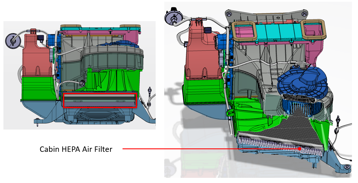
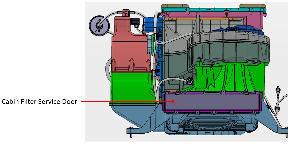
Cabin HEPA Filter (Wet Side)link
Cybertruck has a single HEPA cabin filter located in the wet side HVAC case. The cabin filter service door is accessible by removing an access panel in the front trunk (or frunk).
 |
|---|
| Cabin HEPA Filter (Wet Side) |
 |
|---|
| Cabin HEPA Filter Door (Wet Side) |
Dry Side of the HVAC Caselink
The components of the dry side of the HVAC case are listed below:
- Duct Air Temperature (DAT) sensors (right panel, and left panel)
- Actuators (Defrost, Right Panel, Left Panel, Lower mode)
- Dry side wiring harness
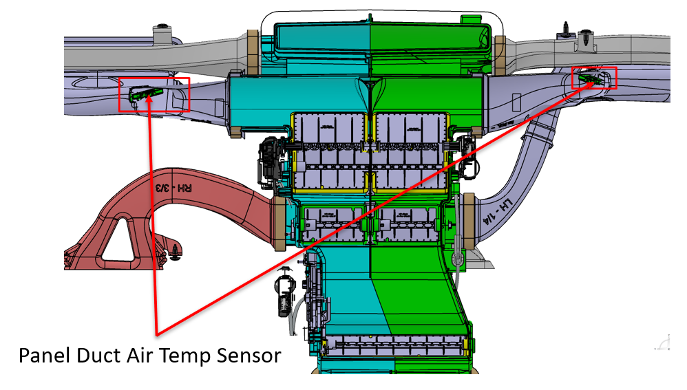
The following DAT sensors are located in the HVAC ducts, not in the HVAC case:
- Driver Panel
- Passenger Panel
- Center Console
Images of the dry side of the HVAC case are shown below.
 |
|---|
| HVAC Case Actuators (Dry Side) |
 |
|---|
| HVAC Case Duct Air Temperature (DAT) (Dry Side) |
 |
|---|
| HVAC Case Duct Air Temperature (DAT) Panel (Dry Side) |
Dry Side HVAC Case – Doorslink
 |
|---|
| HVAC Doors (Dry Side) |
 |
|---|
| Air Inlet / Outlets (Dry Side) |
 |
|---|
| Air Outlets (Dry Side) |
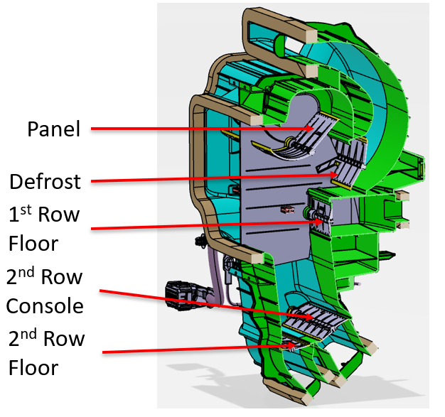
Cabin Airwaveslink
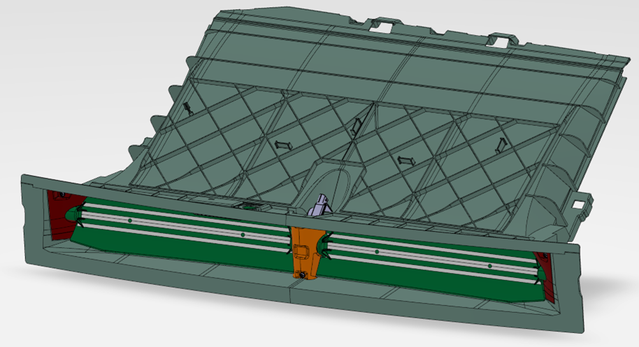
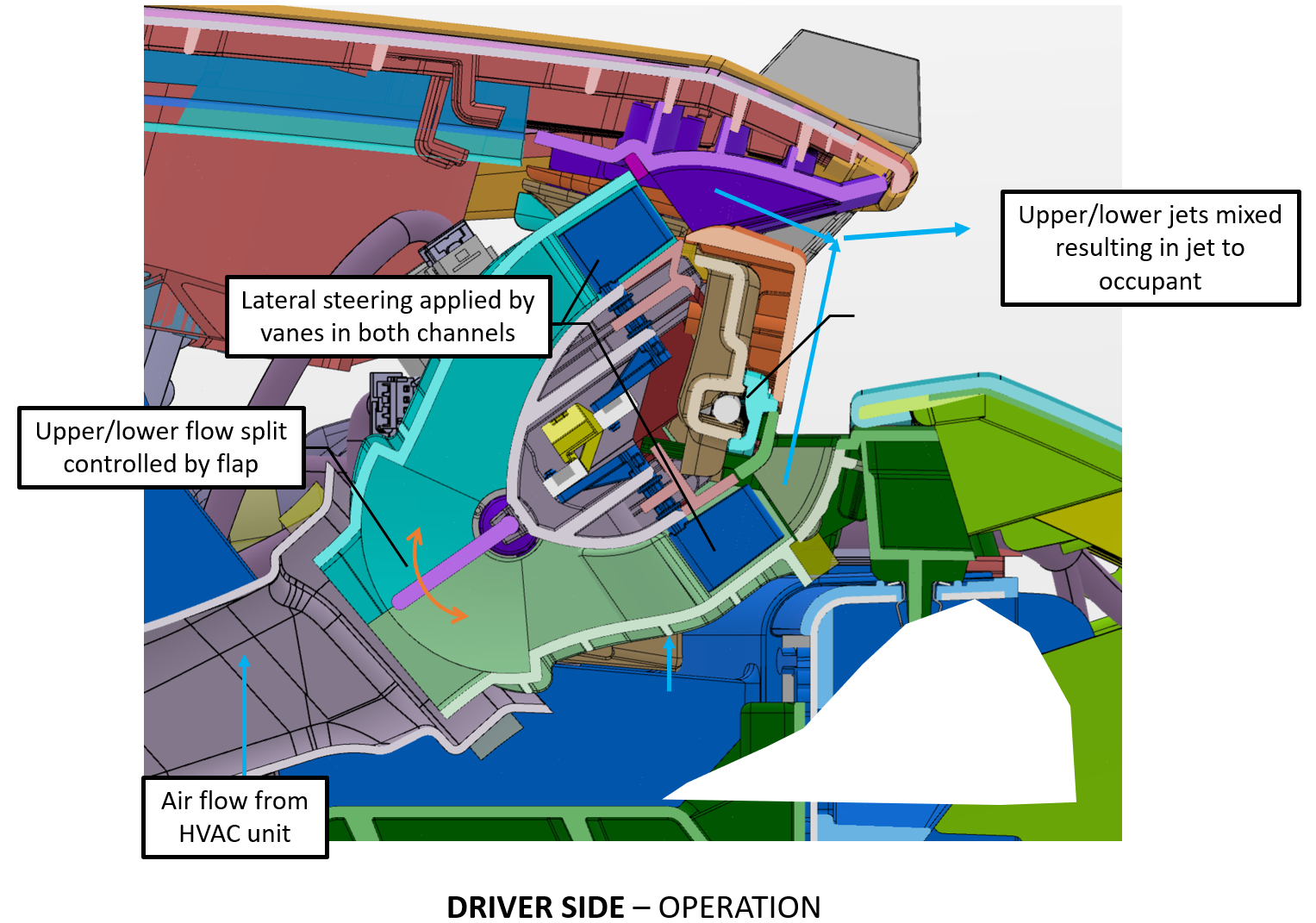
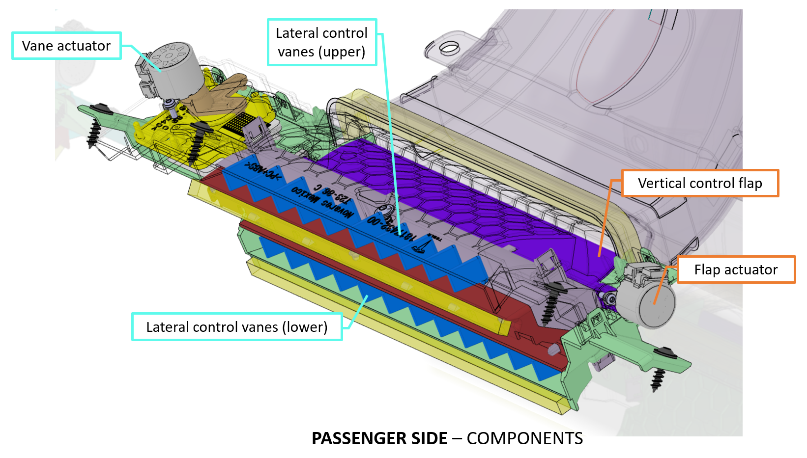
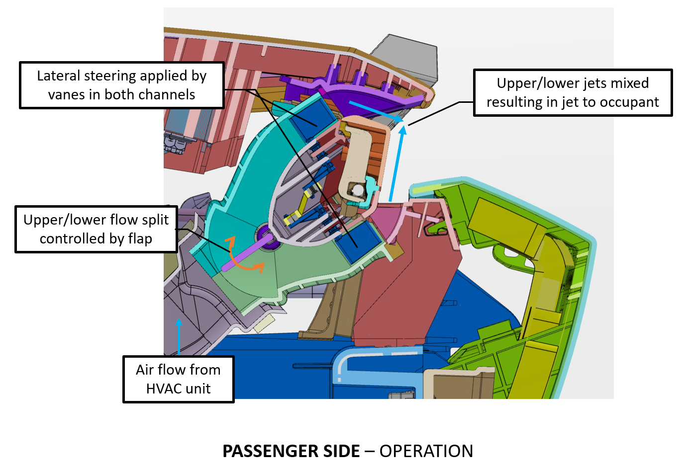
On Cybertruck, the cabin airwaves function similar to other Tesla vehicles. The conditioned air exits the HVAC case through the right and left panel ducts. The upper and lower air flow split is controlled by a flap located in the duct. The flap is controlled by the flap actuator. The upper and lower air jets then mix creating a single air jet to the occupant. Vertical adjustment of the air jet is accomplished by moving the flap in the duct either up or down. Flap up position moves the air jet up while flap down position moves the air jet down.
Right and left side lateral control airflow adjustment is provided by the panel vanes hidden inside the instrument panel. The right panel lateral airflow control is provided by right panel vane actuator. The left panel lateral airflow control is provided by the left panel vane actuator.
Driver Side Airwavelink
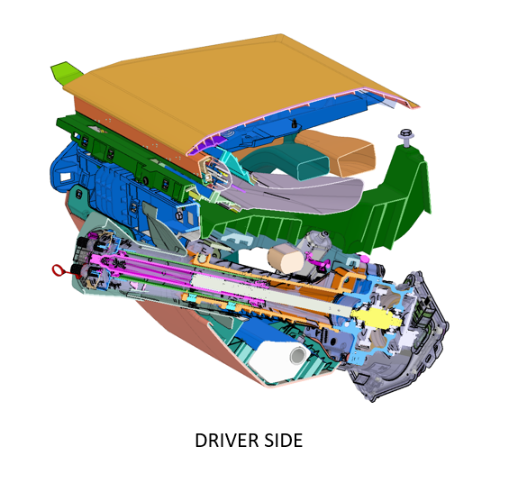 |
|---|
| Driver Side Airwave |
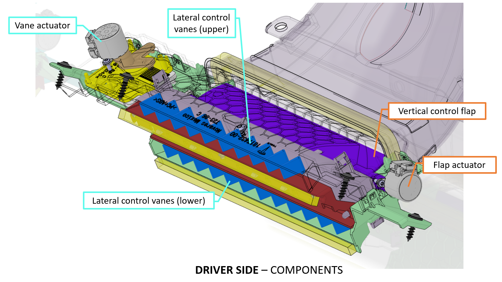 |
|---|
| Driver Side Airwave Components |
 |
|---|
| Driver Side Airwave Operation |
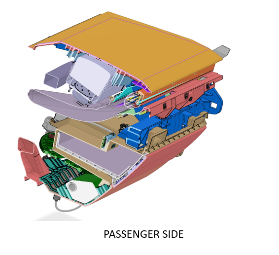
Passenger Side Airwavelink
 |
|---|
| Passenger Side Airwave |
 |
|---|
| Passenger Side Airwave Components |
 |
|---|
| Passenger Side Airwave Operation |
Center Console Airwavelink
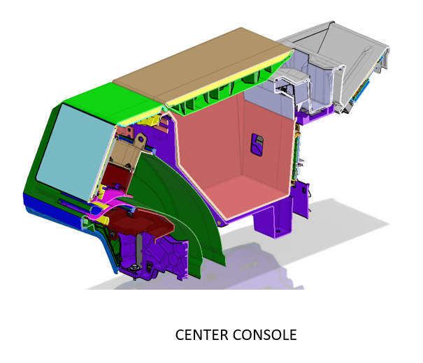 |
|---|
| Center Console Airwave |
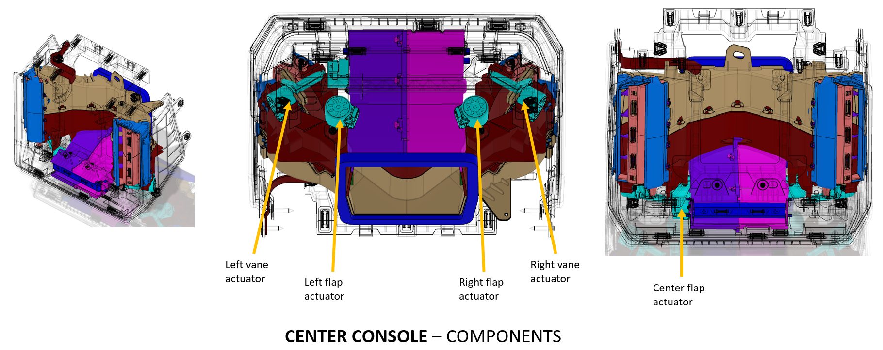 |
|---|
| Center Console Airwave Components |
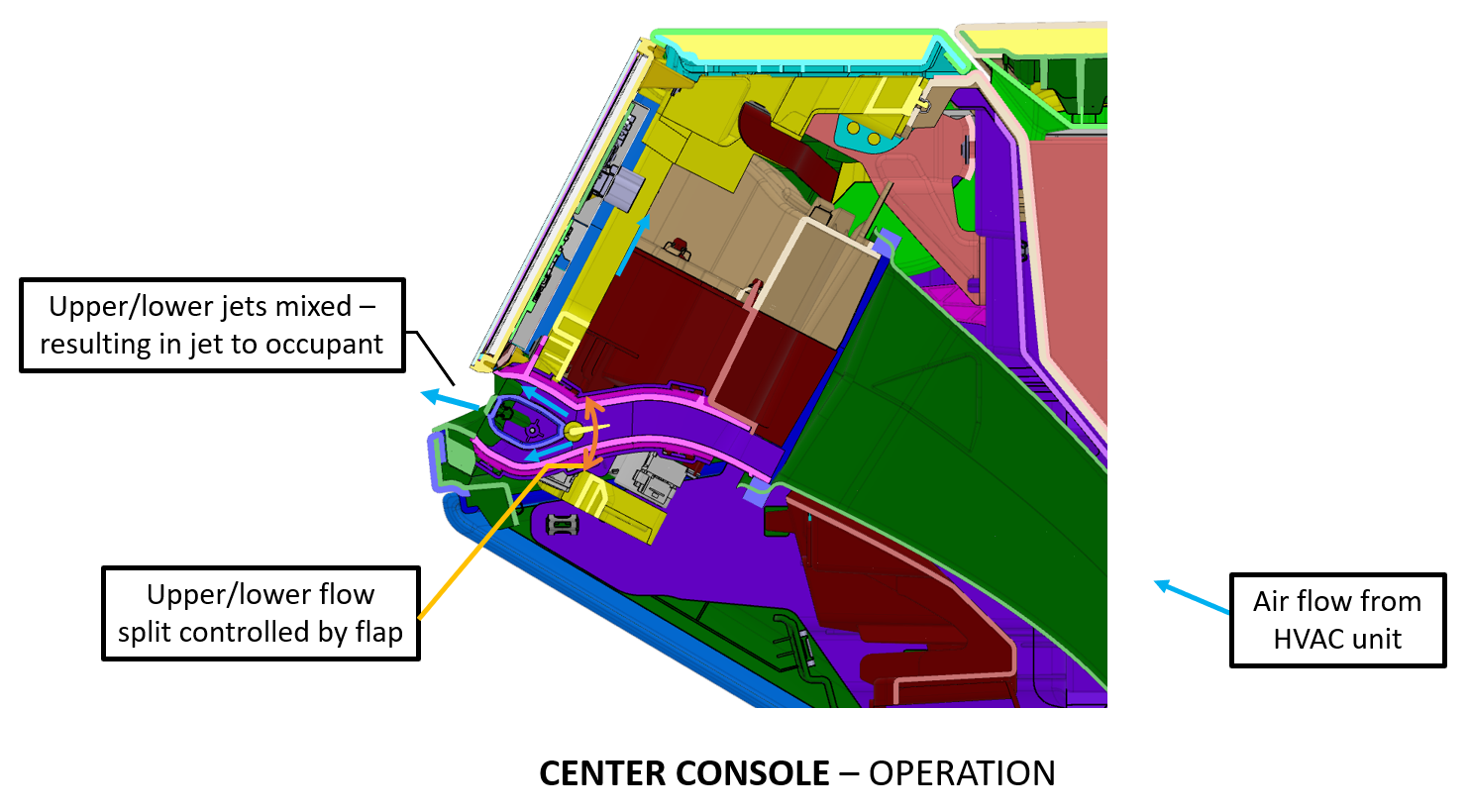 |
|---|
| Center Console Airwave Operation 1 |
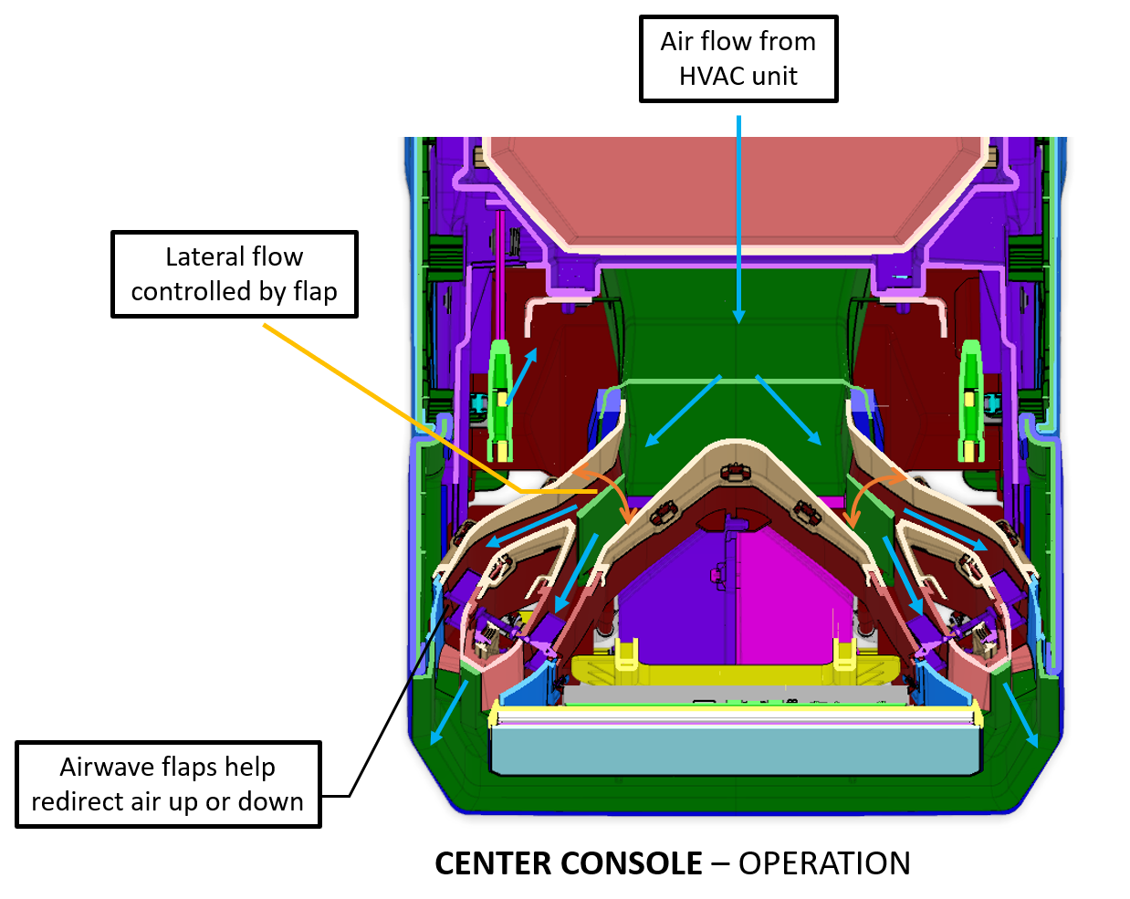 |
|---|
| Center Console Airwave Operation 2 |
Appendix A – Specifications and Capacities Section For Refrigerant and Oil Informationlink
The specifications and capacities for refrigerant and oil are listed below:
- R1234yf refrigerant charge 1020g
- Tesla POE RB100EV oil (part number 1994534-00-A)
- Service A/C Compressor prefilled with (250g) RB100EV oil
Service and Diagnosticslink
When replacing a supermanifold and re-using the compressor, the system should be refrigerant flushed of old oil and old compressor rebalanced with RB100EV oil. The steps to rebalance the compressor oil is listed below:
- Remove the NVH blanket, port caps, port nuts from compressor.
- Locate the manufacture's label on the compressor.
- Note the compressor "dry weight" in grams.
- Locate a scale and zero it.
- Place the compressor on the scale and add oil to the suction port of the compressor until the scale reads = (dry weight + 250g).
- For example, if the dry weight is 7000g and the measured weight of the compressor is 7200g, 50g of oil will need to be added to the compressor until it weighs 7250g.
- Remove the compressor from the scale.
- Re-install the NVH blanket, port caps, and port nuts.
- Install the compressor on the vehicle.