Drive Unitslink
Last updated: September 18, 2024
Overviewlink
Acronymslink
| Acronym | Term |
|---|---|
| DI (F/R/REL/RER) | Drive Inverter (Front/Rear/Rear Left/Rear Right); Also used for Drive Interface |
| DIG | Drive Interface Gateway |
| DSP | Digital Signal Processor |
| DU (F/R/REL/RER) | Drive Unit (Front/Rear/Rear Left/Rear Right) |
| EEPROM | Electrically erasable programmable read-only memory |
| MOSFET | Metal-oxide-semiconductor field-effect transistor |
| OPC | Oil Pump Controller |
| PCBA | Printed Circuit Board Assembly |
| PM (F/R/REL/RER) | Pedal Monitor (Front/Rear/Rear Left/Rear Right); Also used for Permanent Magnet |
| 2PO | Two Phase Open |
| TRA | Torque Reaction Arm |
General Informationlink
Danger
Obey all high voltage safety requirements anytime the drive unit is part of a vehicle repair. The drive unit contains 550uF of internal capacitance, enough to be lethal if the internal discharge functions are not working properly. Always use a multimeter to confirm that dangerous voltage is not present on the DC input connector of the drive inverter.
The motor, gearbox, and drive inverter make up the drive unit assembly. The primary function of the vehicle drive unit is to convert electrical energy from the high voltage battery into mechanical energy in the form of wheel rotation. This is done through the interaction between the motor's magnetic field and electric current in a wire winding to generate torque.
Drive units are secured to the vehicle by three mounts in order to resist axial and rotational forces. Torque is transmitted to each wheel via half shafts connected to the drive unit output flanges. Each drive unit gives motion to the wheels in the respective axle. The two drive units are not mechanically connected to each other.
Long Range Drive Unit Configuration
| Drive Unit | #of Motors | Motor Type | Inverter Type | Gear Ratio |
|---|---|---|---|---|
| Front Drive Unit | 1 | Permanent Magnet Rotor | MOSFET, High Current | 7.5:1 |
| Rear Drive Unit | 1 | Permanent Magnet Rotor | MOSFET, High Current | 9.0:1 |
Plaid Drive Unit Configuration
| Drive Unit | #of Motors | Motor Type | Inverter Type | Gear Ratio |
|---|---|---|---|---|
| Front Drive Unit | 1 | Permanent Magnet Rotor, Carbon Sleeved Rotor | MOSFET, High Current, Thermally Potted | 7.5:1 |
| Rear Drive Unit | 2 | Permanent Magnet Rotor, Carbon Sleeved Rotor | MOSFET, High Current, Thermally Potted | 7.5:1 |
The rear drive unit assembly is located between the rear wheels, underneath the trunk. The Long Range rear drive unit assembly is mounted to the rear sub-frame with three mounts:
- A rear mount, integrated into the gearbox case
- A right mount, integrated into the motor housing
- A left mount, bolted on the gearbox housing above the drive inverter
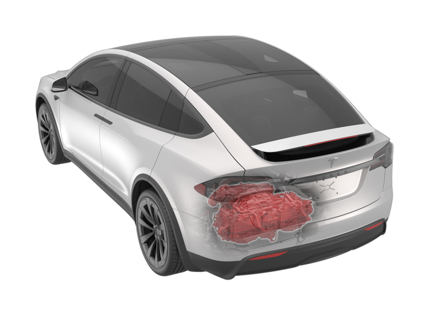 |
|---|
| Rear Long Range Drive Unit - Location |
The Plaid rear drive unit is mounted to the rear sub-frame with three mounts:
- A front mount, integrated into the gearbox case
- A right mount, integrated into the right motor housing
- A left mount, integrated into the right motor housing
|
|---|
| Rear Plaid Drive Unit - Location |
The front drive unit assembly is located under the hood, between the frunk tub and dash panel. The front drive unit is mounted to the body with two mounts:
- A torque reaction arm fastened to the motor housing
- A clevis mount fastened on the gearbox housing
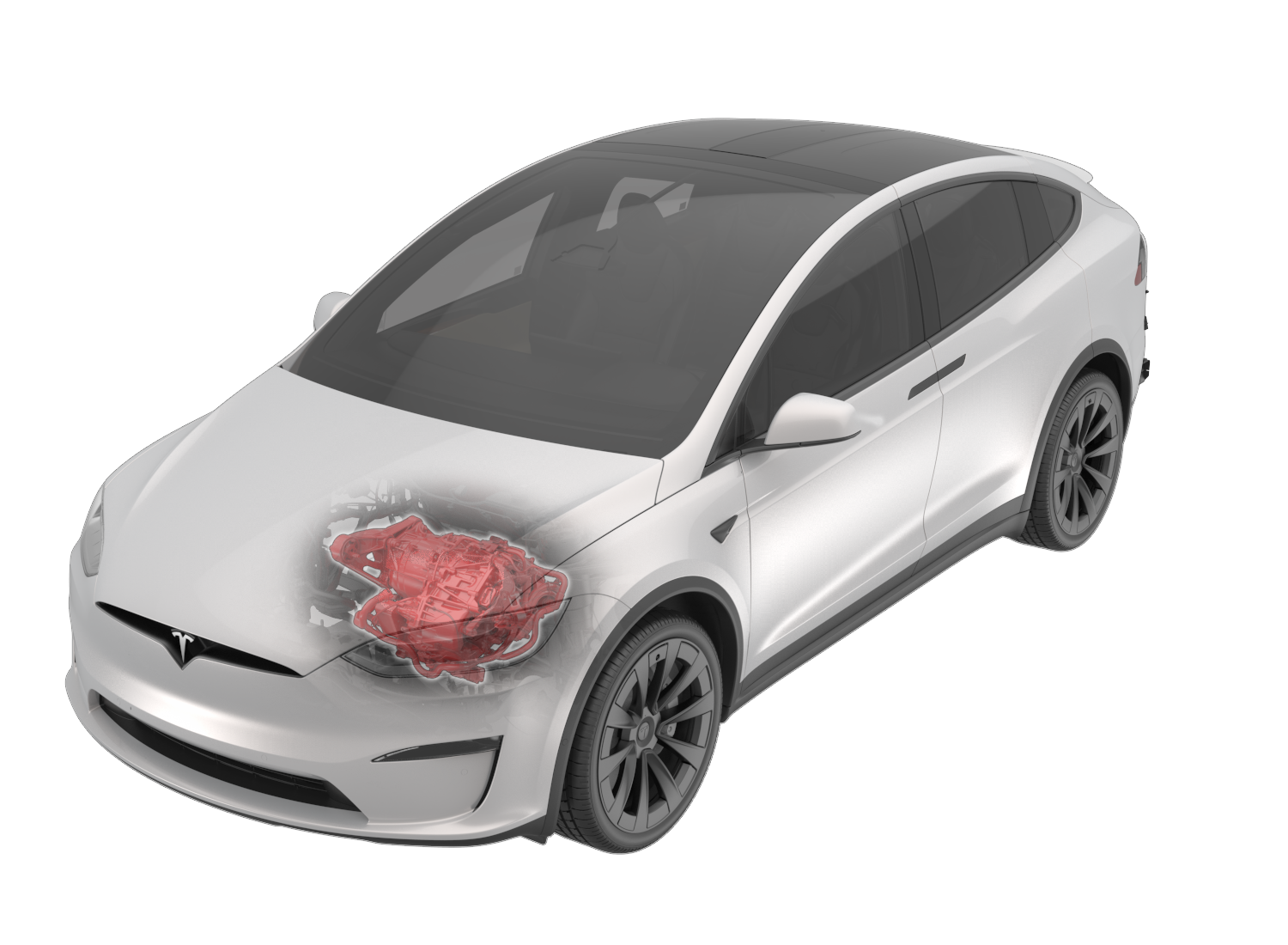 |
|---|
| Front Drive Unit (Long Range & Plaid) - Location |
The drive units connect to the vehicle in six ways:
- High Voltage (HV) Harness
- Low Voltage (LV) Harness
- Half-shafts
- Coolant Hoses
- Mounts
- Ground strap
The drive unit(s) are mechanically and electrically connected to the vehicle.
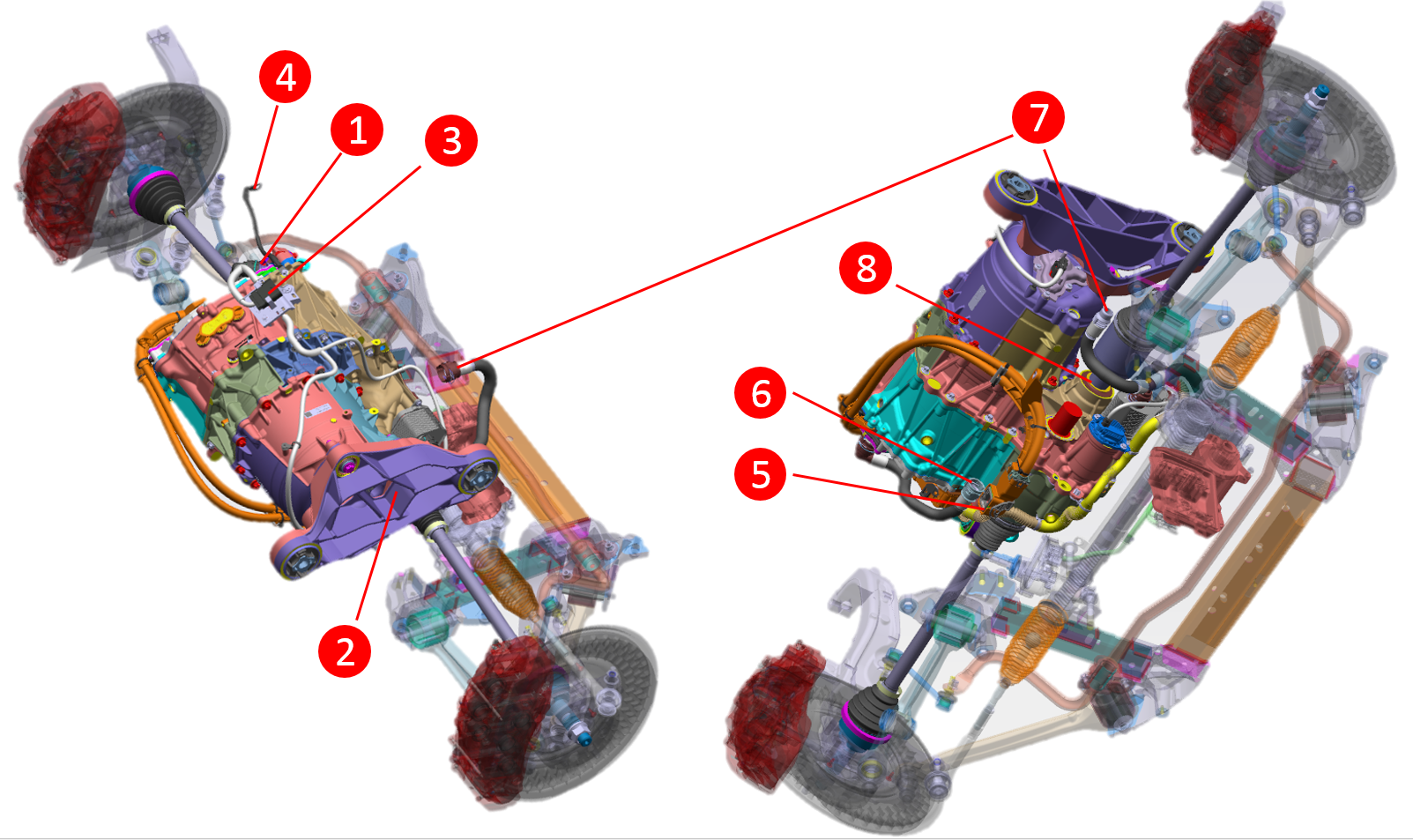
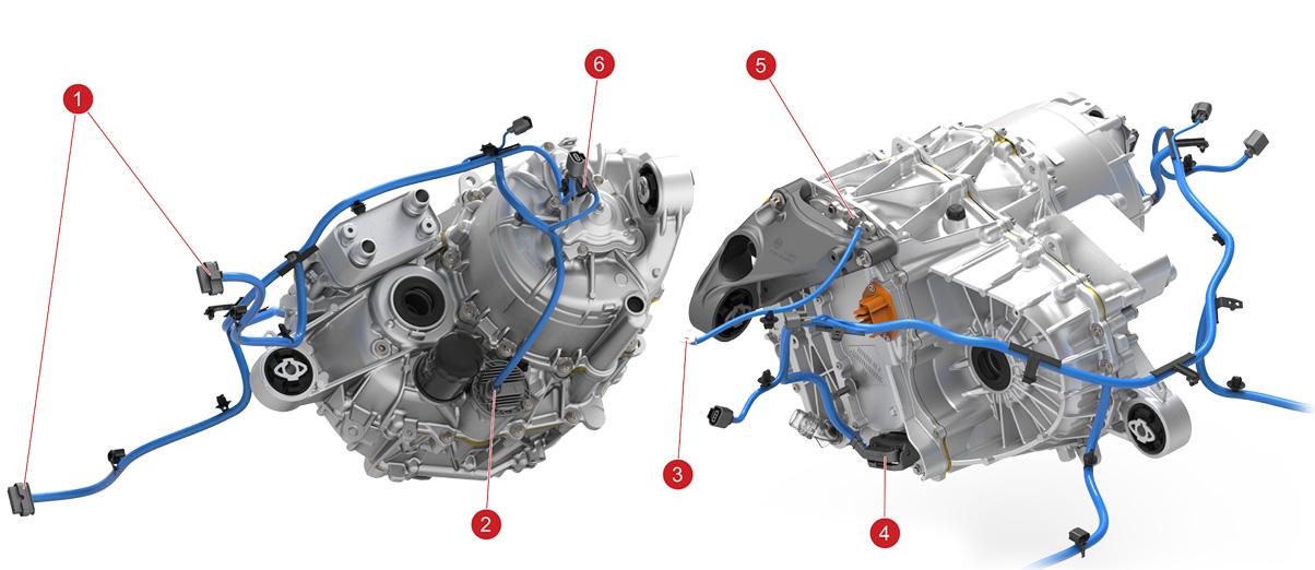
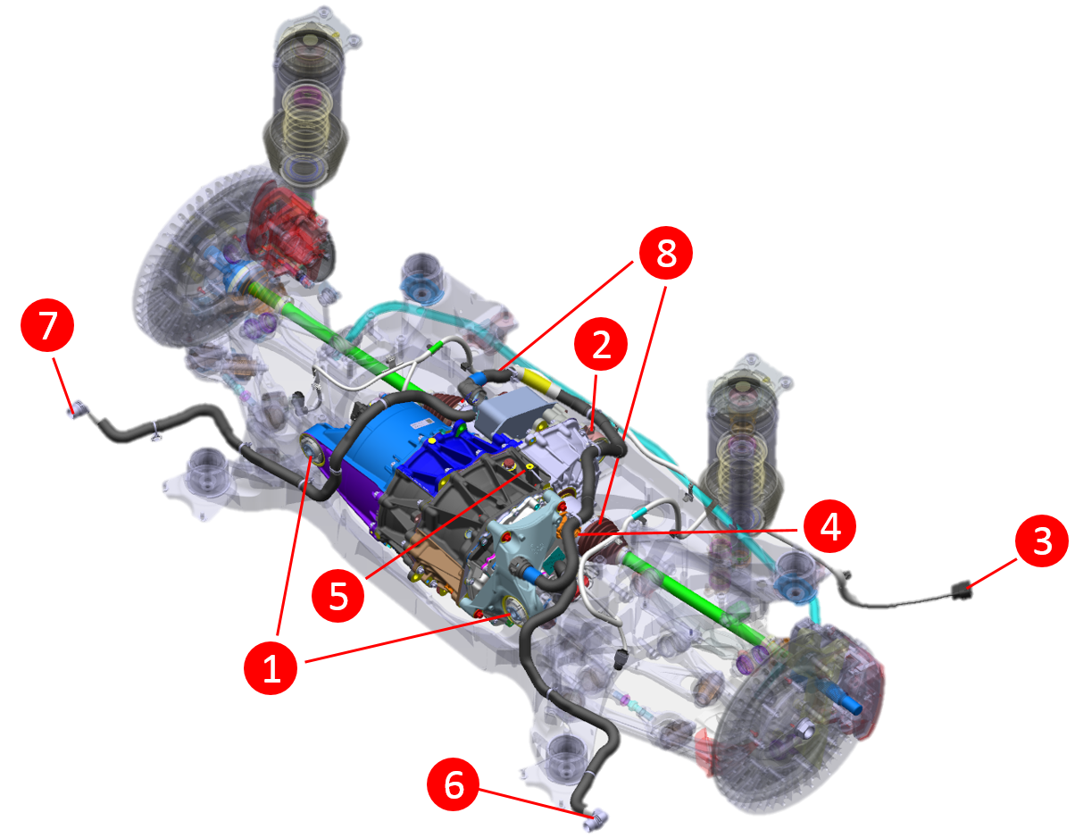 |
|---|
| 1. Left/Right drive unit mount to subframe 2. Rear drive unit mount to subframe 3. Rear subframe low voltage harness connectors (to body) 4. HV battery connector for rear drive unit 5. Drive unit chassis ground point 6. Rear subframe coolant inlet 7. Rear subframe coolant outlet 8. Halfshafts |
| Long Range Rear Drive Unit - Mounting and Connections |
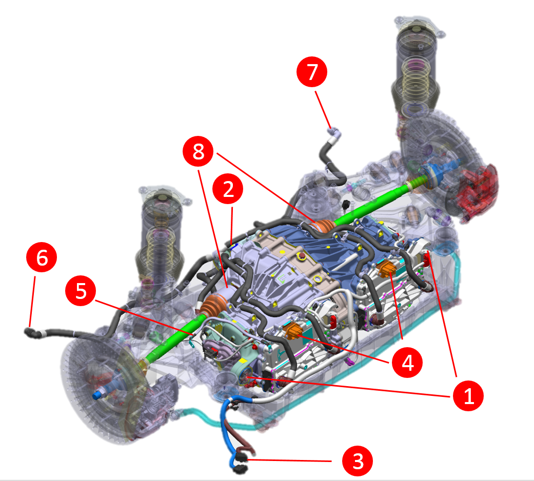 |
|---|
| 1. Left/Right drive unit mount to subframe 2. Front drive unit mount to subframe 3. Rear subframe low voltage harness connectors (to body) 4. HV battery connections to rear drive unit 5. Drive unit chassis ground point 6. Rear subframe coolant inlet 7. Rear subframe coolant outlet 8. Halfshafts |
| Plaid Rear Drive Unit - Mounting and Connections |
 |
|---|
| 1. Clevis mount 2. Torque reaction arm (TRA) 3. Front subframe low voltage harness connector 4. Drive unit chassis ground point 5. HV battery connector to front drive unit 6. Front drive unit coolant inlet 7. Front drive unit coolant outlet (two for performance variant) 8. Halfshafts |
| Front Drive Unit (Long Range & Plaid) - Mounting and Connections |
Drive Unit Mountslink
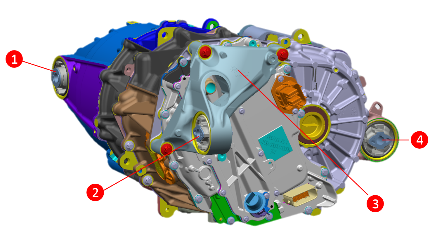 |
|---|
| 1. Right Mount Bushing 2. Left Mount Bushing 3. Left Mount 4. Rear Mount Bushing |
| Long Range Rear Drive Unit Mounts |
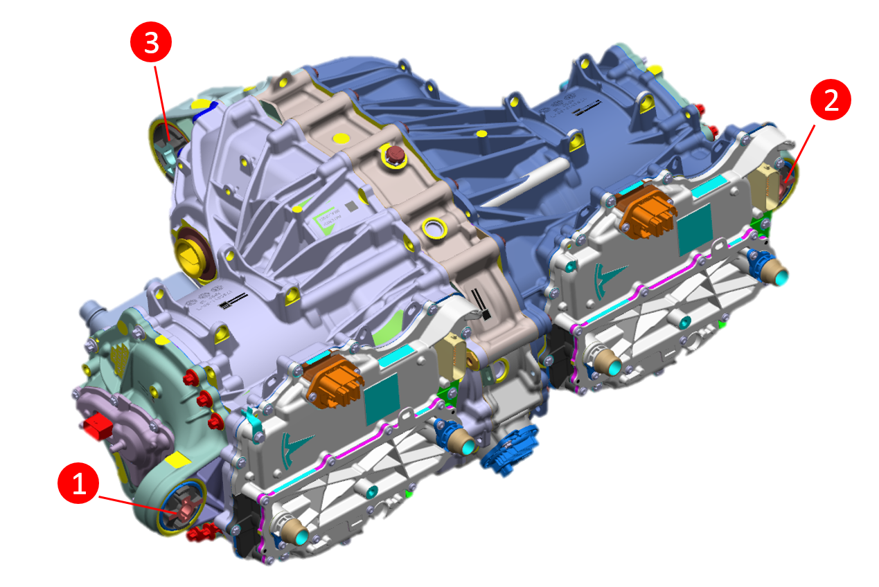 |
|---|
| 1. Left Mount Bushing 2. Right Mount Bushing 3. Front Mount Bushing |
| Plaid Rear Drive Unit Mounts |
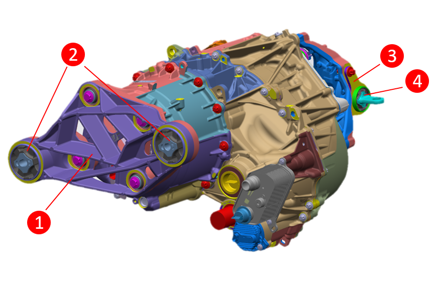 |
|---|
| 1. Torque Reaction Arm (TRA) 2. TRA Bushings 3. Clevis Mount 4. Clevis Mount Bushing |
| Front Drive Unit (Long Range & Plaid) Mounts |
Coolant Hose Connectionslink
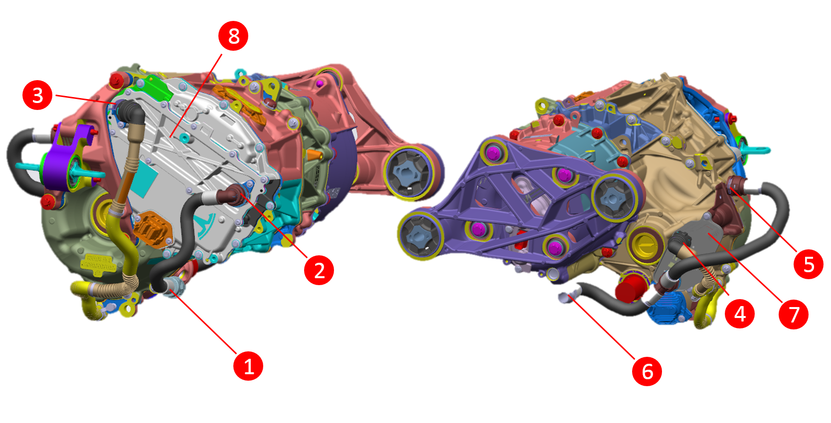 |
|---|
| 1. Front drive unit coolant inlet 2. Drive inverter coolant inlet 3. Drive inverter coolant outlet 4. Heat exchanger inlet 5. Heat exchanger outlet 6. Heat exchanger outlet (Plaid only) 7. Heat exchanger 8. Drive inverter |
| Front Drive Unit (Long Range & Plaid) Coolant Hose Connections |
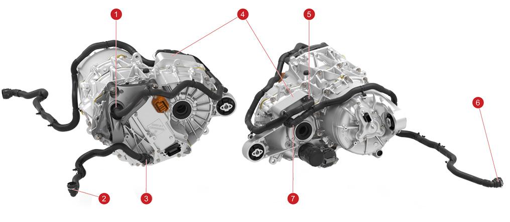 |
|---|
| 1. Drive inverter coolant outlet 2. Rear subframe coolant inlet 3. Drive inverter coolant inlet 4. Heat exchanger 5. Heat exchanger inlet 6. Rear subframe coolant outlet 7. Heat exchanger outlet |
| Long Range Rear Drive Unit Coolant Hose Connections |
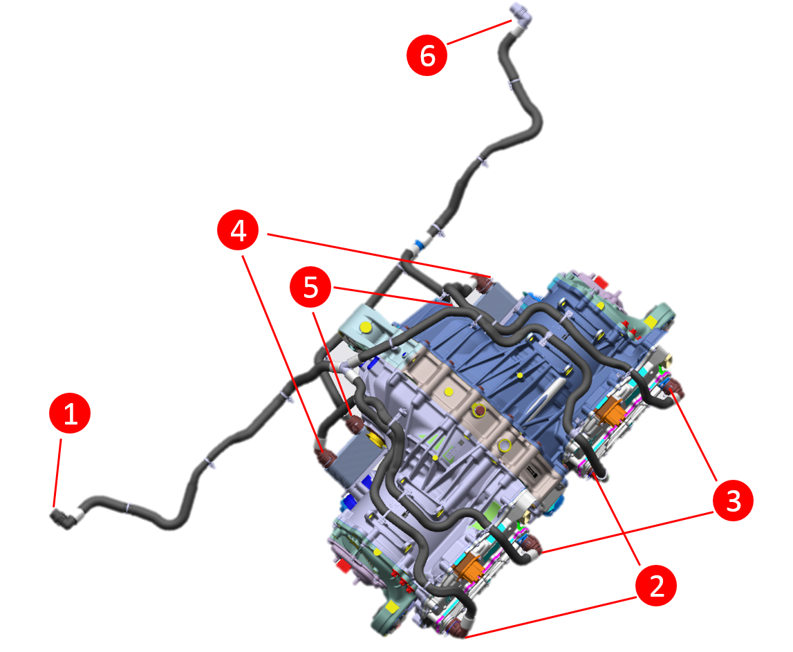 |
|---|
| 1. Rear subframe coolant inlet 2. Drive inverter coolant inlet 3. Drive inverter coolant outlet 4. Heat exchanger coolant inlet 5. Heat exchanger coolant outlet 6. Rear subframe coolant outlet |
| Plaid Rear Drive Unit Coolant Hose Connections |
High and Low Voltage Connectionslink
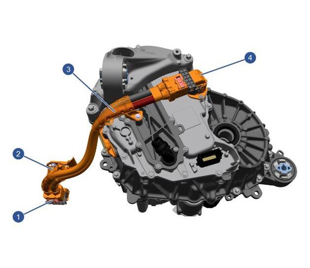 |
|---|
| 1. HV battery connector 2. Drive inverter DC voltage bracket 3. Drive inverter DC voltage bracket 4. Drive unit connector |
| Long Range Rear Drive Unit High Voltage Connections |
Note
Rear Long Range drive unit shown above. The front Long Range and front Plaid drive units are identical.
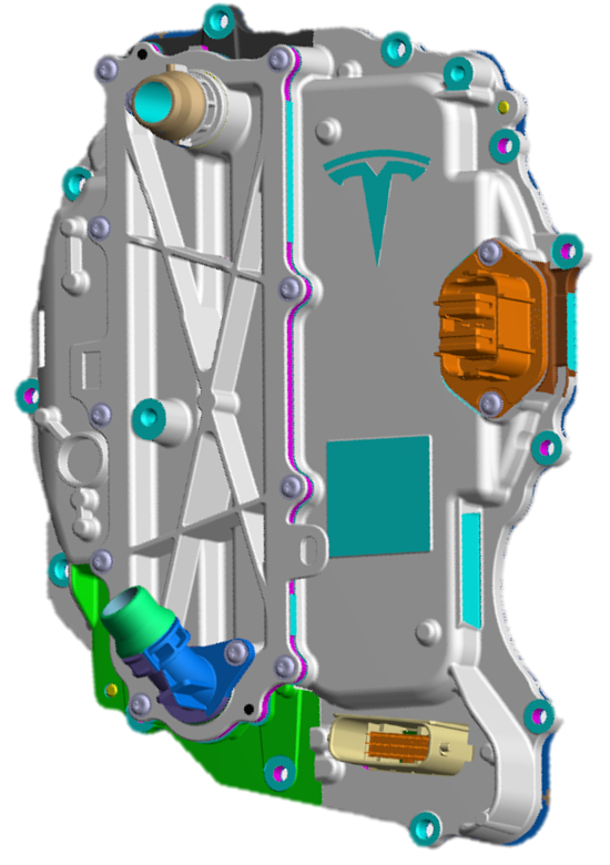
 |
|---|
| 1. Rear subframe harness connectors to body 2. Oil pump connector 3. Ground to chassis 4. Drive inverter logic connector 5. Ground attachment 6. Resolver |
| Long Range Rear Drive Unit Low Voltage Harness Connections |
Note
Long Range rear drive unit shown above. The Long Range front drive unit is identical.
Drive Inverterlink
Overviewlink
The drive inverter converts the Direct Current (DC) from the battery pack into a 3-phase Alternating Current (AC), which is fed into the stator. The current waveforms are 120° out of phase with each other and create a rotating magnetic field in the stator.
In a permanent magnet motor, the permanent magnets inside the motor have a pre-established magnetic field. The interaction of the magnet's field with the stator's rotating magnetic field, produces the motor torque. The speed of the motor depends on the frequency of the AC voltage supplied by the drive inverter. The torque of the motor depends on the amplitude of the AC voltage. In a permanent magnet motor, the torque will also depend on the electrical angle difference between the magnetic field of the stator and the permanent magnets.
 |
|---|
| Drive Inverter |
Each drive inverter translates the torque commands from the external system torque processor, named "Drive Interface", which is located in the left vehicle controller (VCLEFT), into alternating currents that are applied to the motor in order to generate the correct speed, torque, and direction of rotation to move the vehicle. The drive inverter is a bi-directional system, converting battery current to motor current and vice versa. Regenerative braking is achieved using the drive inverter as rectifier to transfer current from the motor to the battery.
Communicationlink
Drive inverter communication architecture on 2021+ Model X is different from previous vehicle models. The new architecture consists of an external system torque processor, named "Drive Interface", which is relocated to the left vehicle controller (VCLEFT). The Drive Interface gets inputs from the gear selector, the accelerator pedal, and the brakes in order to define the operating condition and sends appropriate torque requests to all unit inverters via independent private CAN buses. The Drive Interface has 3 controllers. In addition to the DI and PM controllers, that all unit inverters have, it has a Drive Interface Gateway (DIG), which handles the communication between the private CAN buses and the Vehicle and Party CAN.
The Drive Interface calculates the required torque split for both front and rear motors, along with cruise control and traction control. The unit inverters do not have direct accelerator inputs, so they rely on private CAN bus communication in order to report internal failures to the Vehicle and Party CAN buses. Errors are identified when alerts are received. Alerts are capable of communicating information such as the lack of torque commands from the Drive Interface, or that the Drive Interface is missing in action (MIA).***
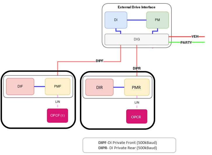 |
|---|
| Long Range Drive Inverter CAN Communication Architecture |
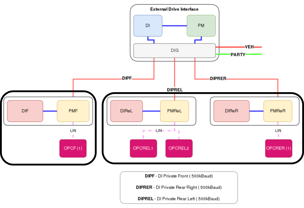 |
|---|
| Plaid Drive Inverter CAN Communication Architecture |
Waste Heat Modelink
2021+ Model X vehicles do not have an external high voltage coolant heater. The battery heating is achieved with the use of the heat pump. Additional to the heat pump, the drive units contribute in heating up the HV battery by providing more heat to support the heat pump or by taking over the battery heating when heat pump is faulty. Both front and rear drive units contribute to waste heat mode. Under cold soak conditions, the front vehicle controller (VCFRONT) sends a request to the drive inverter(s) to produce the necessary power that is required to heat the coolant and, therefore, the HV battery cells. Current is used to heat the stator, without changing the torque/speed output, which heats the surrounding gearbox fluid circulating through the drive unit via the electric pump. The generated heat is then transferred to the coolant at the drive unit heat exchanger.
- If the vehicle is being driven, the motor control strategy changes to produce excess powertrain losses in order to provide heat to the HV battery.
- If the vehicle is stationary, and HV battery requires heating, the drive inverter provides an appropriate current to the motor to produce heat with zero torque/speed change.
Regenerative Brakinglink
Regeneration (regen) operates on the principle that the electric motor can also act as an electrical generator. This places a load on the motor, which in turn provides an additional braking effect.
The amount of regen torque generated is dependent on:
- vehicle speed
- battery state of charge
- accelerator pedal position
- user-specified regen settings
The pedal provides maximum available regen torque when fully released, then proportionally less as the pedal is depressed. The motor delivers zero regen torque when the accelerator pedal reaches its neutral torque position, which moves depending on driving and vehicle conditions.
The drive inverter converts this torque command into the appropriate 3-phase voltage and current waveforms to produce the commanded torque in the motor in the most efficient way. The torque command can be positive or negative. When the torque is used to slow the vehicle, energy is returned to the HV Battery to store for later use.
The maximum regeneration braking profiles take speed and corresponding drag into account to aim for a target total vehicle deceleration rate, not an energy recovery target. Regeneration braking profiles are tailored to everyday driving conditions, and typically provide higher deceleration rates at lower speeds.
Note
A failure of the Antilock Braking System (ABS) or the Electronic Stability Program (ESP) system disables regenerative braking. A notification is displayed on the touchscreen. Regen can also be reduced or disabled when the tires are traction limited, such as loose or slippery surfaces, or during traction control events. Regen will be limited or disabled if battery State of Charge (SOC) is too high.
Temperature Sensorslink
The drive inverter has five temperature sensors:
- Two on heatsink between phases
- One on the heatsink near the fluid port closest to the logic connector
- One on the front of the PCBA near the DSP
- One on the back of the PCBA behind the active discharge resistors.
Other temperatures, such as the DC link capacitor and phase out busbar, are calculated in real time by the main core of the DSP. If the inverter detects any of these temperatures exceeding expected values (if coolant flow is lost for example), it will limit its own power output to an operational level.
Gearboxlink
Overviewlink
All drive units feature a single speed gear reduction gearbox. The gearbox uses a layshaft arrangement with two stage gear reduction.
There is no mechanical linkage between the gear selector and the gearbox. The gearbox gear set is in constant mesh. The gearbox has no mechanical neutral or reverse gear, and no parking pawl. Reverse drive is achieved by reversing the polarity of motor torque. Neutral is achieved by appropriately controlling the permanent magnet motor to produce zero torque.
Plaid rear drive unit features two mirrored gearboxes, one for each of the two motors.
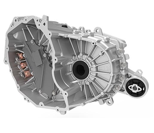 |
|---|
| Long Range Motor Gearbox, Left-hand Side |
Note
Long Range rear motor gearbox shown above. The front Long Range and front Plaid drive units are similar.
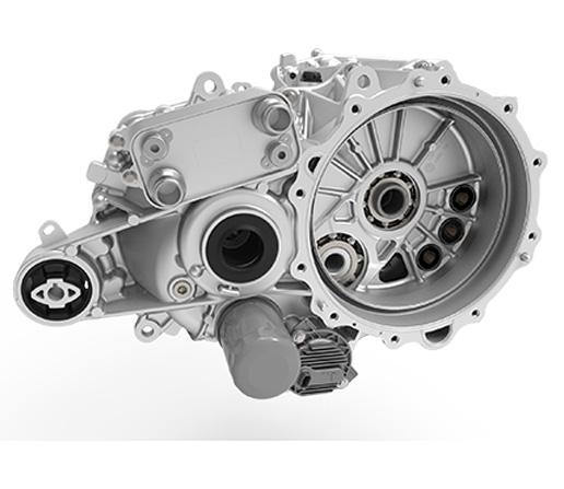 |
|---|
| Long Range Motor Gearbox, Right-hand Side |
Note
Long Range rear motor gearbox shown above. The front Long Range and front Plaid drive units are similar.
Description and Operationlink
Output Gear (Differential)link
Long Range Front/Rear and Plaid Front Drive Unitslink
The open differential is a conventional design with the differential carrier bolted to the final drive ring gear. The housing supports the differential pin, side gears, and pinion gears. The differential assembly is supported in the gearbox assembly using deep groove ball bearings.
The differential allows the road wheels to turn at different speeds while providing an equal amount of torque. The integral spline on the drive shaft meshes with the side gear on the differential assembly. When the drive shaft rotates and the wheels are traveling at the same speed, torque is applied to the complete assembly; the pinion gear does not rotate. Torque is transmitted to the road wheels through the drive shafts. During cornering, the inner wheel travels a shorter distance at a lower speed. This results in the pinion gears rotating about the outer wheel side gear, therefore increasing the speed of the outer wheel.
Plaid Rear Drive Unitlink
The Plaid rear drive unit does not use a differential, since each of its motors directly drives the corresponding wheel via a dedicated reduction gearbox. This allows for fully independent torque control at each wheel, and the ability to simulate any type of open, limited slip, or fully locking differential without any drawbacks or energy losses. This flexibility allows the vehicle to extract the highest amounts of grip, performance, and handling depending on the operating conditions and driver requests.
Oil Pumplink
The drive inverter controls the electric oil pump based on the drive unit operating conditions and thermal requirements. The electric oil pump can be driven independent of drive unit speed, which allows for optimized controls in order to:
- Improve drive unit efficiency
- Improve thermal system performance
- Enables waste heat mode.
This is achieved by transferring energy in the form of heat, from the oil circulating inside the drive unit to the vehicle coolant circuit, via the heat exchanger.
The oil pump is a Tesla in-house component in order to gain full control of electronic control unit (ECU) hardware and firmware. The oil temperature is detected and reported by the oil pump thermistor. The temperature is allowed to vary within a given range. When the temperature exceeds the design limits, an alert is triggered and the performance of the drive unit is limited. If there is insufficient flow of oil in the drive unit, the same outcome is to be expected.
Due to the dry sump design, the Plaid rear drive unit has two types of oil pumps. Two scavenge pumps, and one feed pump. The performance characteristics of each pump type are optimized for their application, hence these components are not interchangeable. The scavenge pump has an additional inlet on the side of the housing.
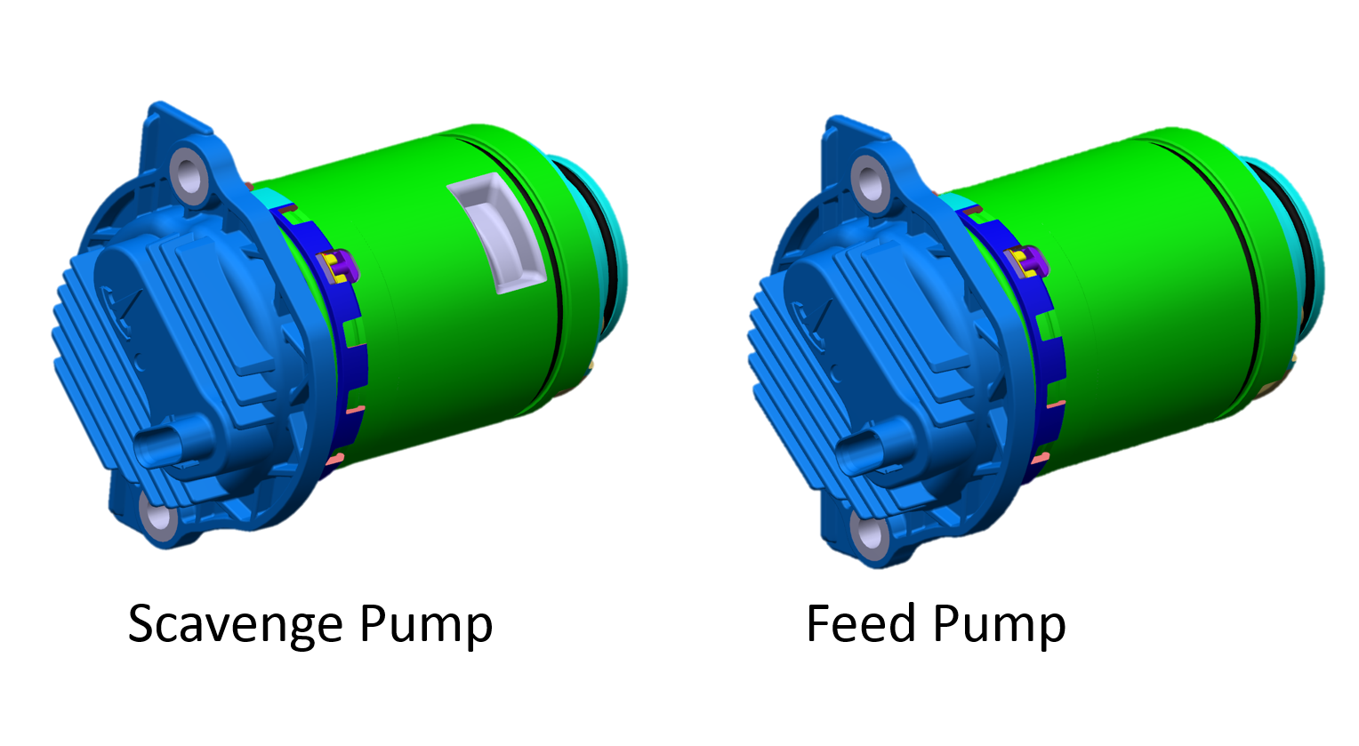 |
|---|
| Scavenge Pump vs Feed Pump |
A built in mesh screen is located at the inlet of the oil pump to catch any debris that could potentially damage the pump.
Motorslink
Overviewlink
There are different types of motors to serve different purposes, but all of them follow the same principles. The torque in every electric motor is created is by two magnetic fields that interact to each other, causing forces that rotate the rotor. Depending on the way that the necessary magnetic fields are created, the motors are divided in different categories.
Permanent Magnet Motorlink
2021+ Model X vehicles use synchronous permanent magnet (PM) motors on the front and rear axles. In permanent magnet motors, the magnets always have an established magnetic field in the rotor. When the stator windings are fed with 3-phase AC current, a rotating magnetic field is also established in the stator. If the stator was fed by DC current, the magnets of the neighboring rotor magnetic pole would be attracted, causing the rotor to move until the magnets are aligned with the peak of the stator magnetic field. However, in this case, the rotor would stop moving after reaching this position.
When applying AC current, the magnets of the rotor are continuously “chasing” the peak of the rotating magnetic field of the stator. The torque in the permanent magnet motors varies by controlling the amplitude of the stator current and the internal angle between the magnets and stator magnetic fields. The 2 fields rotate synchronously (there is no frequency difference between them) and this is the reason that this type of motors are also called Synchronous motors. "If the current supply of the stator suddenly stops, there is still remaining magnetic field in the motor because of the existence of the magnets. The motor controller is responsible for detecting any abnormal operation and eliminating impact to the system.
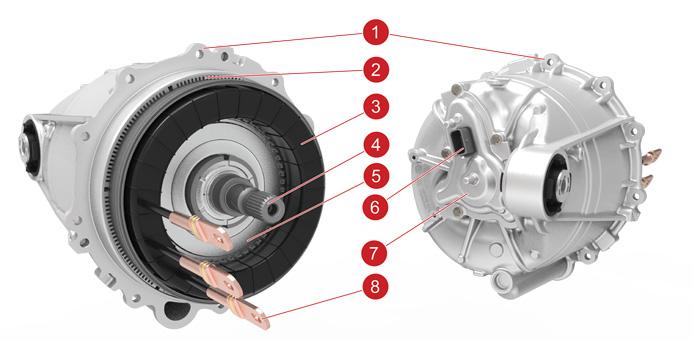 |
|---|
| 1. Stator housing 2. Stator steel 3. Stator windings 4. Rotor shaft 5. Rotor balance ring 6. Resolver 7. Resolver cover 8. 3-Phase lugs |
| Permanent Magnet Motor |
Note
Long Range rear motor shown above. The front Long Range and front/rear Plaid drive units are similar.
Motor Speed Sensor (Resolver)link
All 2021+ Model X drive units use a resolver to sense the speed of the rotor. Unlike the encoders which are speed sensors, the resolver directly measures the angle of the rotor. Speed measurements are derived from position measurements made over time. A resolver works similarly to a transformer where the amount of coupling between primary and secondary coils is determined by the angle of the resolver rotor (press fit onto the motor rotor) relative to the resolver stator (in the resolver cover assembly).
Stator Temperature Estimationlink
The stator temperature is not measured, but estimated using the oil pressure and temperature. Oil pressure and oil flow alerts can be expected when the stator is not operating under its nominal temperature range.