High Voltage Distributionlink
Last updated: December 11, 2024
Overviewlink
This document focuses on the distribution of high voltage power among all HV components. Each high voltage component that is not directly used for HV distribution is detailed in other Theory of Operation documents.
The HV distribution architecture is influence by the powertrain configuration of the vehicle. Model 3 offers Rear Wheel Drive (RWD) and All Wheel Drive (AWD) / Dual Motor configurations.
- All configurations have the high voltage (HV) battery located in the chassis of the vehicle, between the 4 wheels of the car.
-
All Wheel Drive configuration has one front drive and one rear drive unit:
- The front drive unit is located on the front subframe, between each front wheel.
- The rear drive unit is located on the rear subframe, between each rear wheel.
-
Long Range and Standard Range RWD have a single drive unit located on the rear subframe, between each rear wheel.
Model 3 vehicles built before 2020 are equipped with a Positive Temperature Coefficient (PTC) heater and a compressor. The compressor and its refrigerant loop is used to cool the cabin and the PTC heater to warm it.
For cabin and powertrain thermal heating / cooling on Model 3 vehicles built after 2020, the HV system uses a heat pump. The HV system does not use a PTC heater (dedicated cabin heater), nor does it use a coolant battery heater. The HV system uses the heat pump to generate heat in the cabin and uses waste heat mode in the drive inverter, along with the heat pump to generate heat for the HV battery. For more details, refer to the section 'High Voltage Battery Thermal Management' in the Non-Structural High Voltage Battery Theory of Operation.
The HV distribution design minimizes complexity, cost, and weight, with most connections consolidated within the HV battery and no separate HV connection components. The HV system includes the following components:
- High voltage battery serves as the primary energy source for the vehicle.
- Drive inverter(s) featuring waste heat mode, which heats the coolant and eliminates the need for a dedicated coolant heater component.
- The Power Conversion System (PCS), located in the HV battery ancillary bay, which supports
- DCDC conversions
- LV to HV conversion for precharging the DC link bus before closing pack-contactors.
- HV to LV conversion once contactors are closed to power the LV bus and manage LV battery state of charge.
- AC to DC conversion for charging vehicle on AC power.
- Cabin heating, ventilation, air conditioning (HVAC) system.
- High Voltage Devices to manage high voltage distribution
- Battery pack contactors manage the energy transfer from the HV battery to the DC link, supplying power to other high voltage components.
- Fast charge contactors used to facilitate direct current charging.
- Pyro disconnects to interrupt the HV loop when necessary
- Shunts to measure current flow
- Charge port assembly and charging harness for charging.
The illustration below provides a general overview of how the HV is distributed from the HV battery to all HV components, which creates the powertrain of the vehicle.
 |
|---|
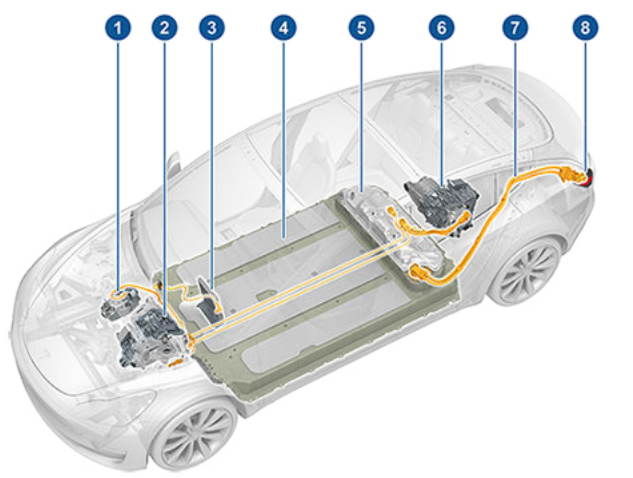
| 1. A/C compressor 2. Front drive unit (if equipped) 3. PTC heater for cabin heating 4. High Voltage battery 5. Ancillary bay cover for access to High Voltage electronics 6. Rear drive unit 7. High Voltage cable to charge port 8. AC/DC Charge port |
| Pre-2020 HV Distribution Overview (without Heat Pump) |
 |
|---|
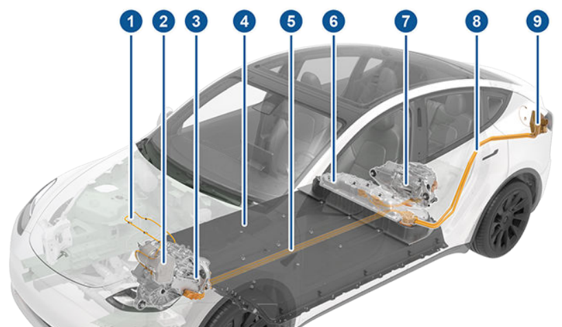
| 1. High Voltage Cabling to Heat Pump Compressor 2. Heat Pump Compressor 3. Front drive unit (if equipped) 4. High Voltage battery 5. HV cables running in HV battery tunnel to front of vehicle for supply to compressor and PTC heater (if equipped) 6. Ancillary bay cover for access to High Voltage electronics 7. Rear drive unit 8. High Voltage cable to charge port 9. AC/DC charge port |
| Post-2020 HV Distribution Overview (with Heat Pump) |
Most of the HV connections and branching are located inside the ancillary bay of the HV battery.
Location of High Voltage Componentslink
Location of High Voltage Batterylink
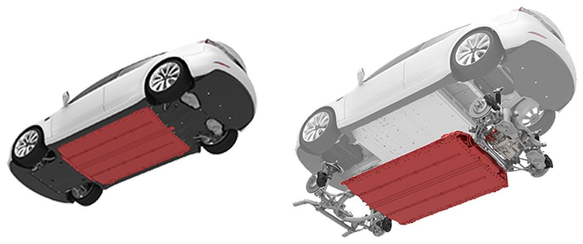
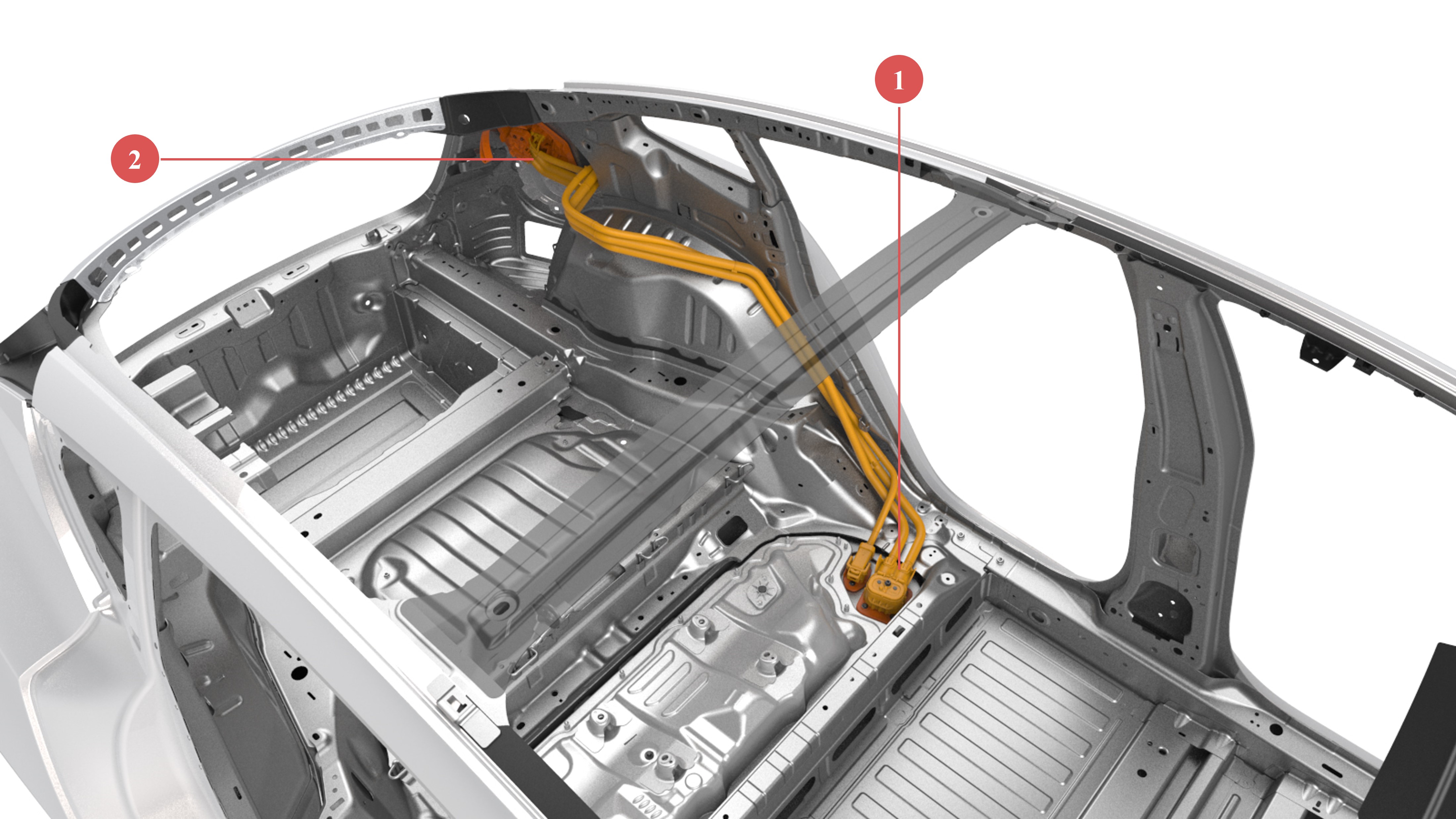
The HV battery is located between the rear and front subframes of the vehicle. The high voltage battery is mounted to the chassis of the vehicle, from underneath. This gives easy access to removal and installation from the bottom of the vehicle and gives the vehicle exceptional performance due to the lower center of gravity.
The ancillary bay of the HV battery, which contains most of the HV devices of the HV battery, is located at the top rear of the HV battery on top of the modules. For more details, refer to the .
 |
|---|
| Non-Structural HV Battery Location |
Location of Drive Unitslink
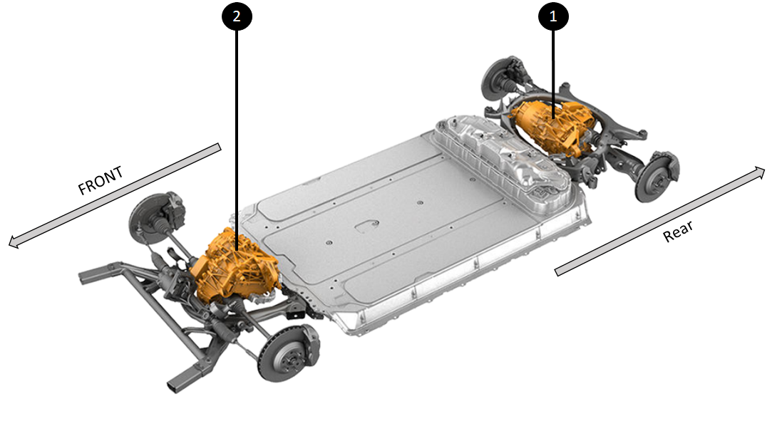
For Long Range/Dual Motor configurations, the rear drive unit is located in the rear subframe between the two rear wheels and the front drive unit is located in the front subframe between the two front wheels.
For Rear Wheel Drive (RWD) configurations (both Standard Range and Long Range), a single drive unit is mounted on the rear subframe, between the two rear wheels.
See the Drive Unit Theory of Operation for more details.
 |
|---|
| 1. Rear Drive Unit 2. Front Drive unit (Dual Motor configuration only) |
| Drive Unit Locations |
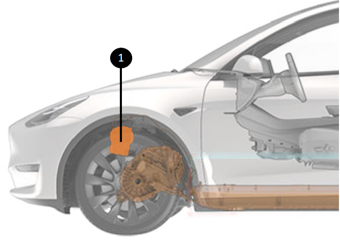
Location of HV A/C Compressorlink
The HV A/C compressor is located between the firewall and the front trunk of the vehicle. The location of the heat pump compressor is behind the firewall for both the structural and non-structural HV battery vehicles. However, the firewall is located in different places in each variant.
Note
Model 3 vehicles built after 2020 use the heat pump compressor. The location of the compressor is the same whether the vehicle was built before or after 2020.
 |
|---|
| 1. AC heat pump compressor |
| Heat Pump Compressor Location |
Location of Power Conversion Systemlink
The functions of AC charging and DCDC conversions are handled by the Power Conversion System (PCS). There is no dedicated AC charger or DCDC device in the vehicle.
The PCS (highlighted in blue) is located on the ancillary bay of the HV battery. For more details, refer to the Non-Structural High Voltage Battery Theory of Operation.
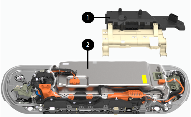 |
|---|
| 1. HVC 2. PCS underneath the HVC |
| Location of the PCS |
High Voltage Build Up in the High Voltage Batterylink
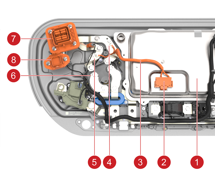
High voltage is generated in the modulesand distributed to the ancillary bay. The high voltage has to go through the pack-contactors to be able to energize the ancillary bay. More information on the pack-contactors is available in the Non-Structural High Voltage Battery Theory of Operation. The high voltage in the ancillary bay is directly distributed to the shunt, pyrotechnic fuse disconnect, rear drive unit, cabin heater, and the HV A/C compressor. The diagram below helps visualize those connections within the HV battery and the ancillary bay.
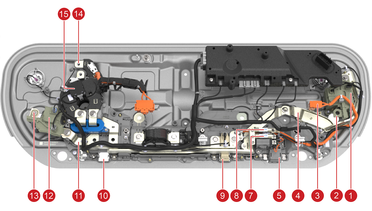 |
|---|
| 1. Positive pack-contactor 2. Pack-contactor ring for HV battery positive 3. DC link HV PCS connector 4. Positive DC link busbar 5. HV connector for compressor 7. HV thermal Fuse on HV A/C compressor positive link 8. HV thermal fuse on PCS DC positive link 9. HV connector to rear drive unit 10. HV connector to front drive unit 11. Negative DC link bus bar 12. Negative contactor 13. Contactor terminal that connects to HV battery minus 14. Terminal to bus bar charge port ancillary bay connector 15. Fast charge contactors |
| HV Connections in the Ancillary Bay |
The PCS has a short connection to the high voltage, enabling current to flow in both directions: from PCS to DC link/HV battery during AC charging, and vice versa for 12V power support.
High Voltage Battery and High Voltage Component Interfaceslink
DC Link to Power Conversion Systemlink
Although the PCS is not used when fast charging, it is connected to the DC link of the HV battery for the following functions:
- Precharging the DC link but to pack voltage before closing contactors.
- Stepping down high voltage from the HV battery to lower voltage to support the low voltage bus of the vehicle.
For more details, see Non-Structural High Voltage Battery Theory of Operation.
The DC side of the PCS DC is connected as follows to the HV battery DC link:
The HV positive terminal of the PCS is connected to the positive DC link busbar, which is supplied by the positive pack-contactor. A 63A fuse is installed between the PCS HV connection and the busbar to provide overcurrent protection. The PCS HV negative connection is made via a cable that is bolted to the main DC link negative busbar using a round terminal, which in turn connects to the negative pack-contactor. The negative link from the DC link to the PCS is not fused, unlike the positive link.
 |
|---|
| 1. HV DC connector to/from PCS 2. DC positive cable to/from PCS 3. 63A fuse on the DC positive leg of PCS connection 4. DC negative cable to/from PCS 5. DC negative busbar to negative pack-contactor 6. DC positive busbar to positive pack-contactor |
| Connection of PCS to DC Link HV |
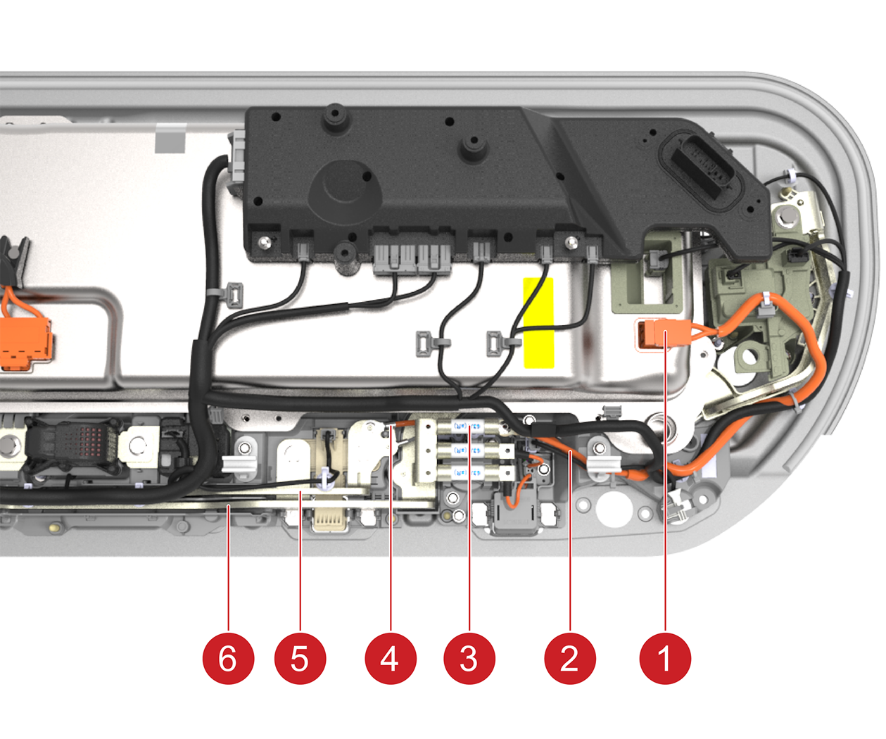
AC Input to Power Conversion Systemlink
The PCS converts AC input from wall power through the charge port to DC voltage when charging the HV battery.
 |
|---|
| 1. PCS 2. AC input to the PCS 3. Harness for AC input to PCS 4. Connection of PCS AC input 1 to charge port connector busbar 5. Connection of PCS AC input 2 to charge port connector busbar 6. Fast charge contactors 7. Connector to charge port harness 8. three-phase AC input Connector for EMEA and APAC |
| Connection of PCS to AC Input |
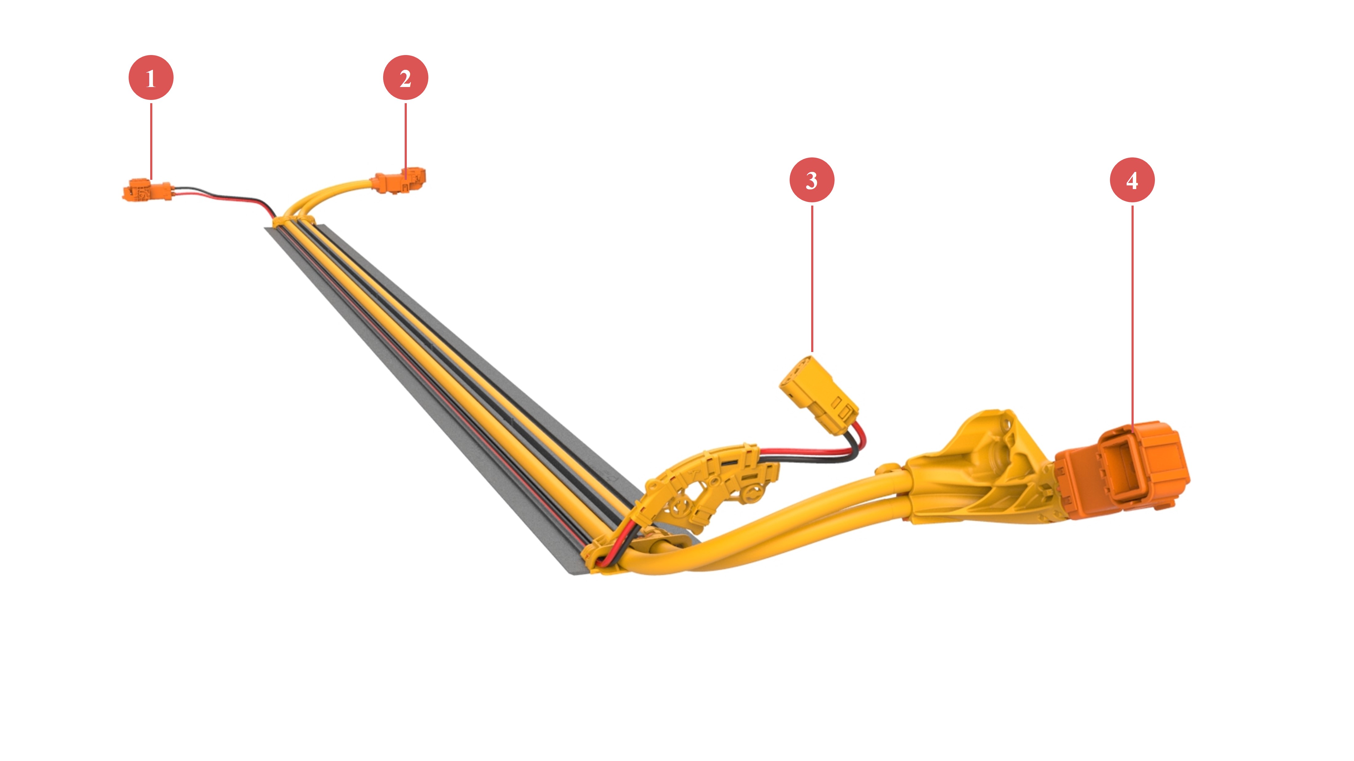
Front Drive Unit and HV A/C Compressorlink
The front drive unit and HV A/C compressor are both located in the front of the vehicle, between the firewall and the front trunk (or frunk).
Both HV components use a similar routing from the ancillary bay to the front of the vehicle. The HV routing for the front drive unit and HVAC starts from two of the high voltage connectors at the rear of the ancillary bay. The front drive unit and HVAC have a joined connection to HV battery.
 |
|---|
| 1. Connectors to HVAC 2. Connector to front drive unit |
| HV Connections to Front Drive Unit and HVAC |
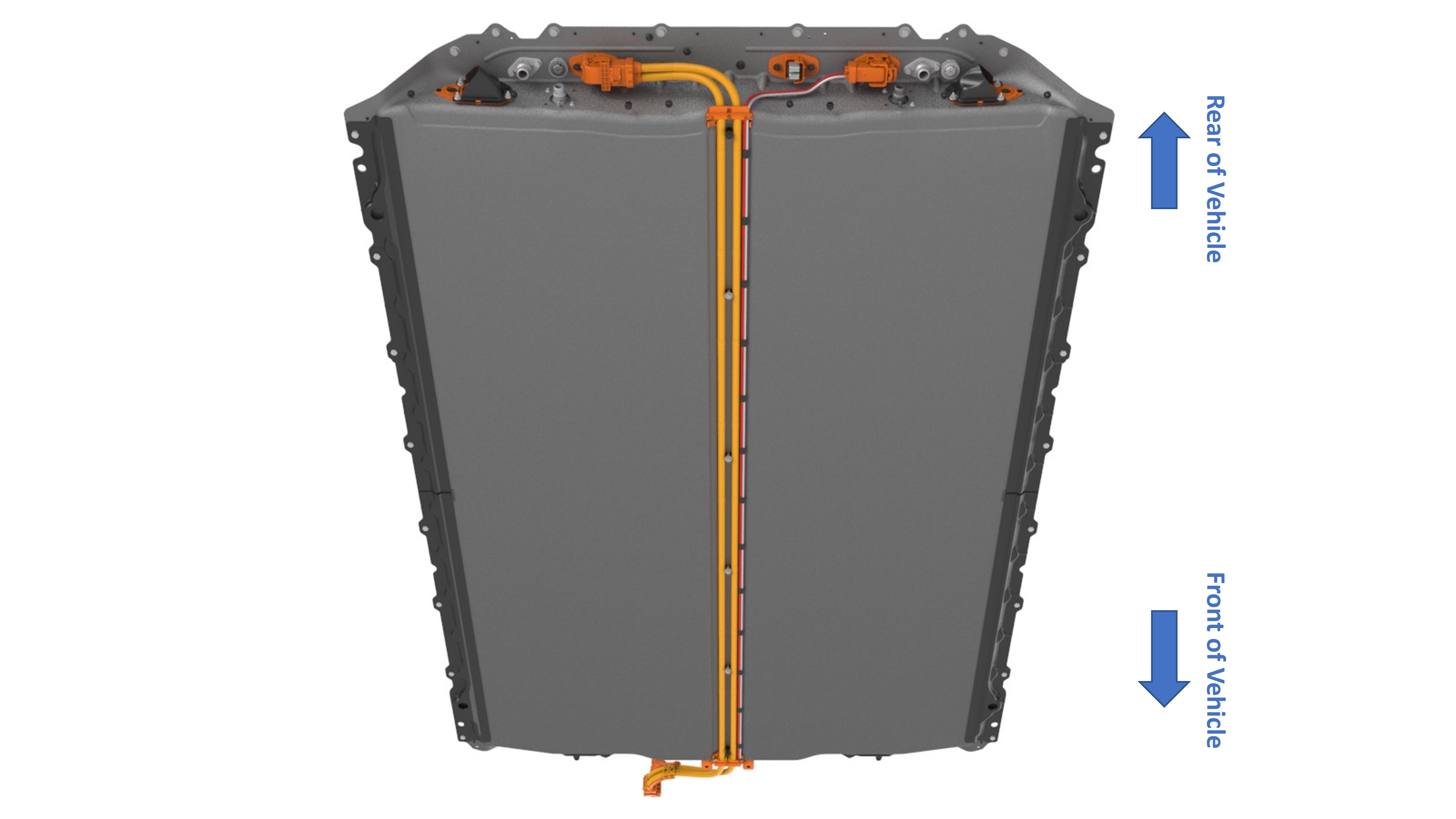
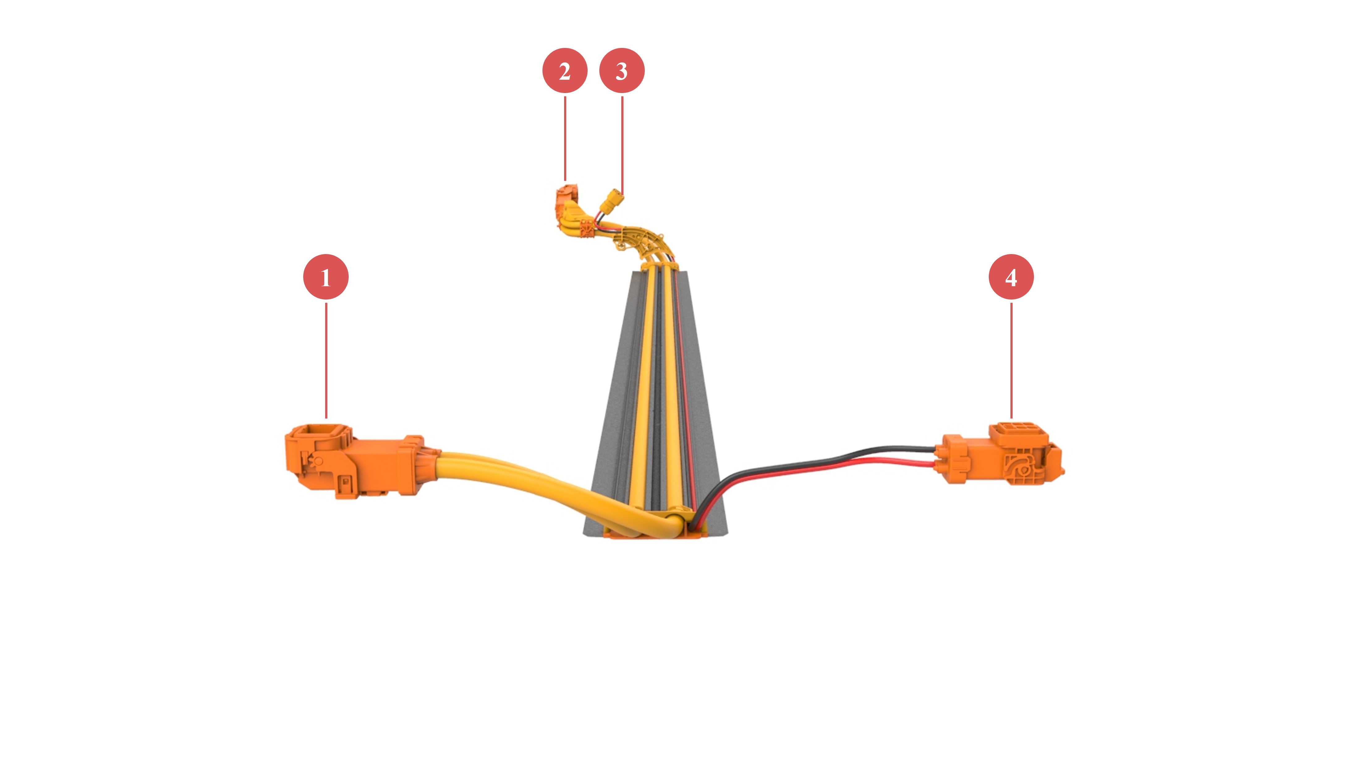
The HV cables to the front drive unit and HVAC are bundled when leaving the ancillary bay, and then they go under a small tunnel under the HV battery to the front of the vehicle. The 4 cables (2 per HV component) exit the tunnel, which is protected by a skid plate all along the HV battery length, to the front of the vehicle and are each terminated with respective connectors.
 |
|---|
| HV Cables Traveling From Back to Front of Vehicle Under Center Tunnel of HV Battery |
 |
|---|
| 1. Connector to HVAC 2. Connector to Front Drive Unit |
| Connectors at the Front of the HV battery |
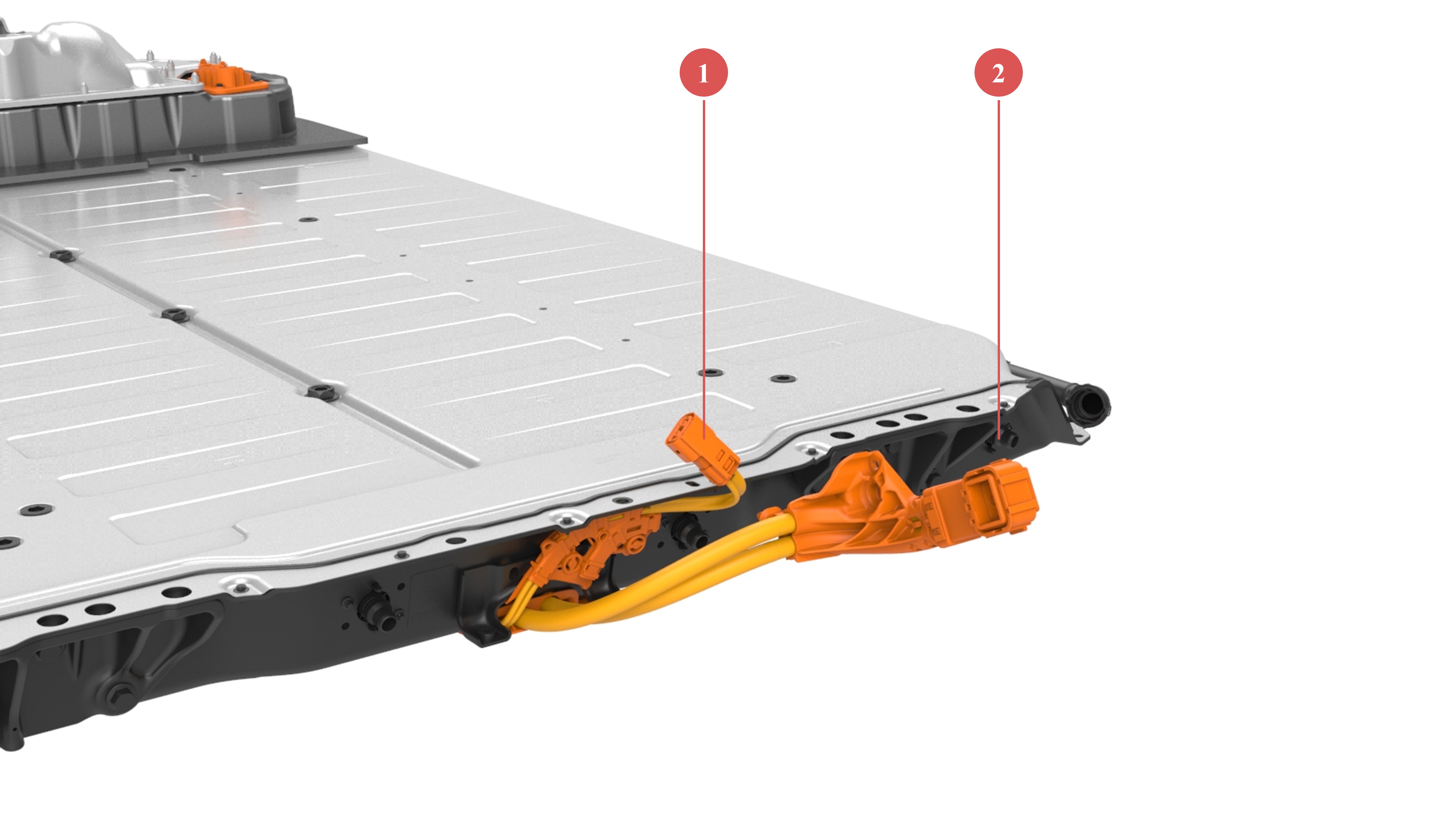
The illustrations below give a visual representation of the routing and connectors. For more details on the connectors at the front drive unit, refer to the Drive Units Theory of Operation. For more details on connectors of the HVAC, refer to the Thermal Management Theory of Operation.
 |
|---|
| 1. Rear side HVAC harness connector to battery 2. Rear side front drive unit harness connector to battery 3. HV connector to HVAC 4. HV connector to front drive unit |
| (HV harness route under HV battery) |
 |
|---|
| 1. Connector to HV battery of front drive unit harness 2. Connector to front drive unit 3. Connector to HVAC 4. Connector to HV battery of HVAC harness |
| Connectors to HV battery |
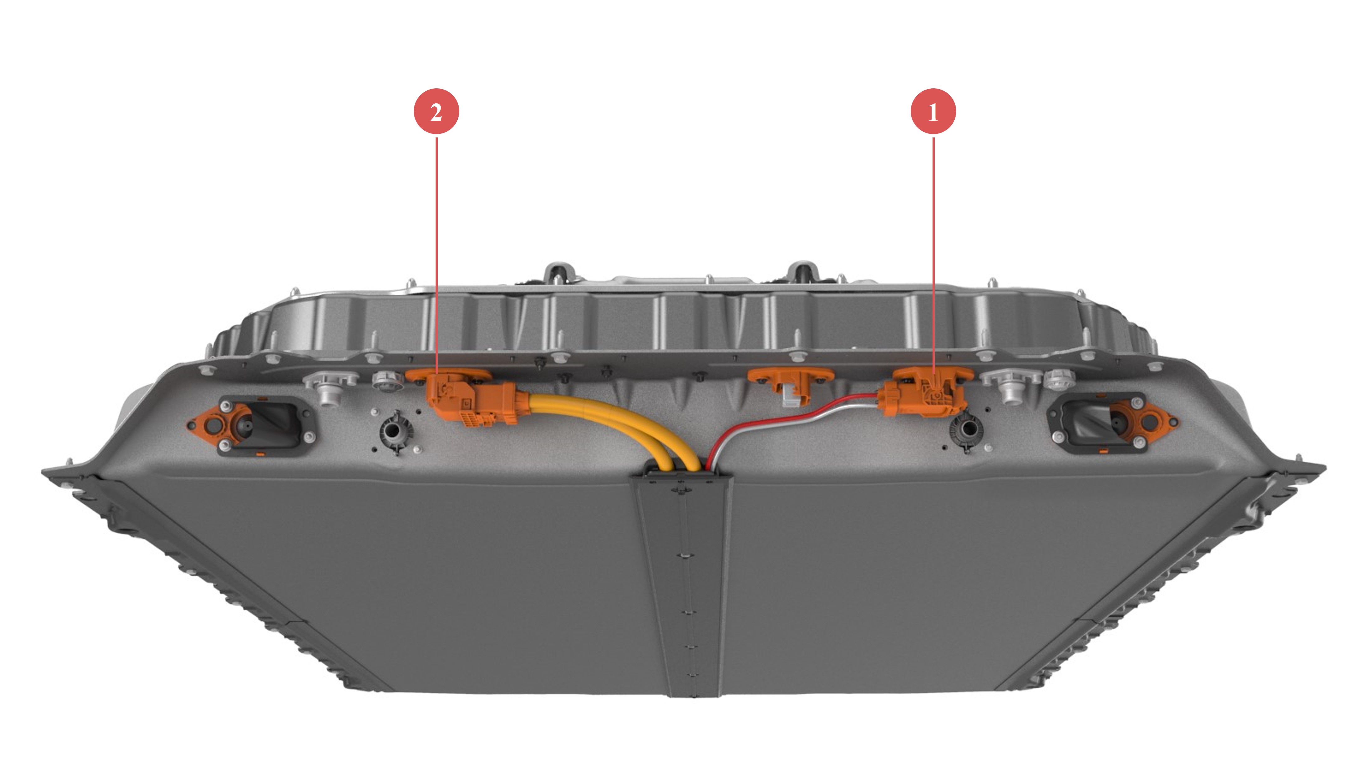
High Voltage Battery to Rear Drive Unitlink
The HV routing for the rear drive unit starts from the high voltage connector at the rear of the ancillary bay. The harness is dedicated to the rear drive unit and is composed of two HV cables. The harness is short in length to rapidly reach the drive unit. For more details, refer to the Drive Units Theory of Operation.
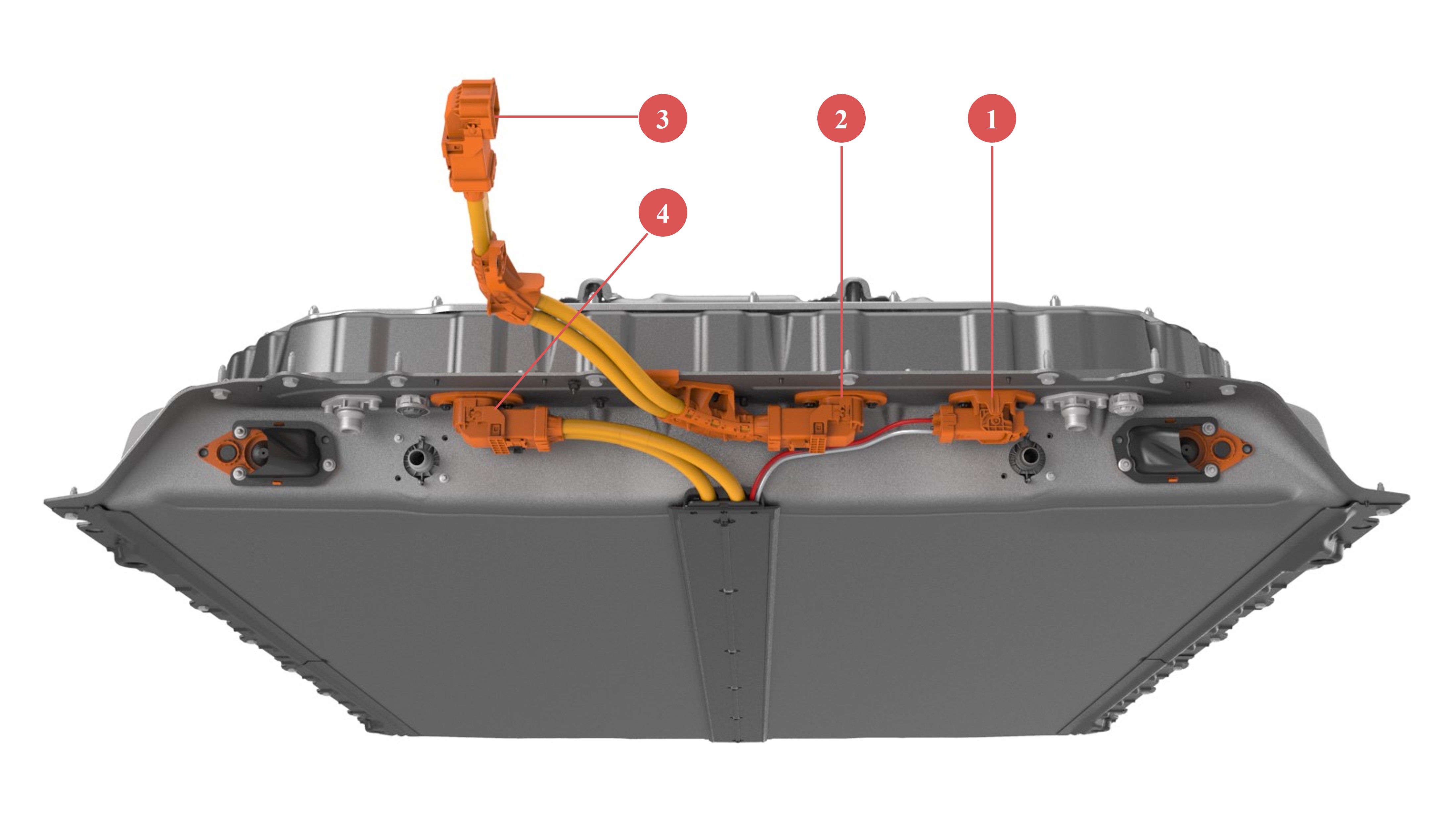 |
|---|
| 1. Connector to HVAC 2. Connector for rear drive unit harness to HV battery 3. Connector to rear drive unit 4. Connector to front drive unit |
| HV connectors on the rear side of HV battery |
Charge Port Connectionslink
The high voltage routing for the charger port starts from the high voltage connector at the rear of the HV battery. From there, refer to the section on Alternating Current (AC) and Direct Current (DC) connection to Power Conversion System (PCS) internally to the HV battery.
 |
|---|
| 1. HV busbar joint point to ancillary bay 2. HV busbar joint point to charge port |
| Charge Port HV Connections |