Car Computer
Overviewlink
The Infotainment system is the main user interface and informational hub of the vehicle. It allows for the display of live vehicle data like speed, drive state, door states, HV battery information, Autopilot visualization and more. It also manages the connection of a user's phone for calls, messaging, and calendar integration. Other high-level vehicle features such as audio, cabin climate, driver profiles, vehicle settings and software updates are made possible by the infotainment system.
System on a chip that runs a Linux-based operating system and serves as the main controller of the infotainment system.
18.5” center display touchscreen and a 9.4” rear display with touchscreen
Controller that routes live vehicle data to and from the infotainment SOC and logs vehicle diagnostic data.
Cellular and Wi-Fi connections allow the vehicle secure communication with Tesla servers, navigation data, streaming apps, online gaming, and software updates.
ADSP on the infotainment board communicates to distributed amplifiers which drive 15 speakers and 2 subwoofers.
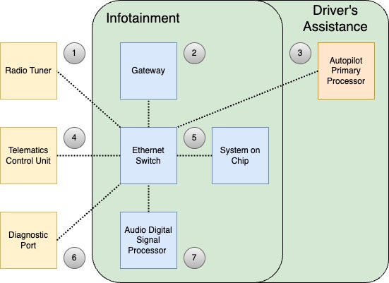
A local ethernet network which allows fast communication between the infotainment SOC and other infotainment components like the vehicle Gateway, Tuner, ADSP, and TCU.
Power Sequencelink
Understanding the order in which the different infotainment system componenets are powered up can help in diagnosing any power supply issues.
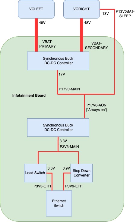
 Constant power is provided to the Infotainment board by two 48V parallel sources: the VCLEFT and VCRIGHT. This voltage is then stepped down to an "always on" 17V rail (P17V0-AON), which powers up the Gateway.
 Once the Gateway is powered up and booted into its normal application, it switches on the power rails for a number of components:
- Gateway SD Card
- Ethernet Switch
- Etherloop Switch
- TCU
- Center Display
- Infotainment SOC
- ADSP
 Once the SOC boots successfully, it then switches on more perpherials:
- USB-BT
- Rear Display
 After all the perpherials are powered on, the Infotainment system is ready for use.
Specificationslink
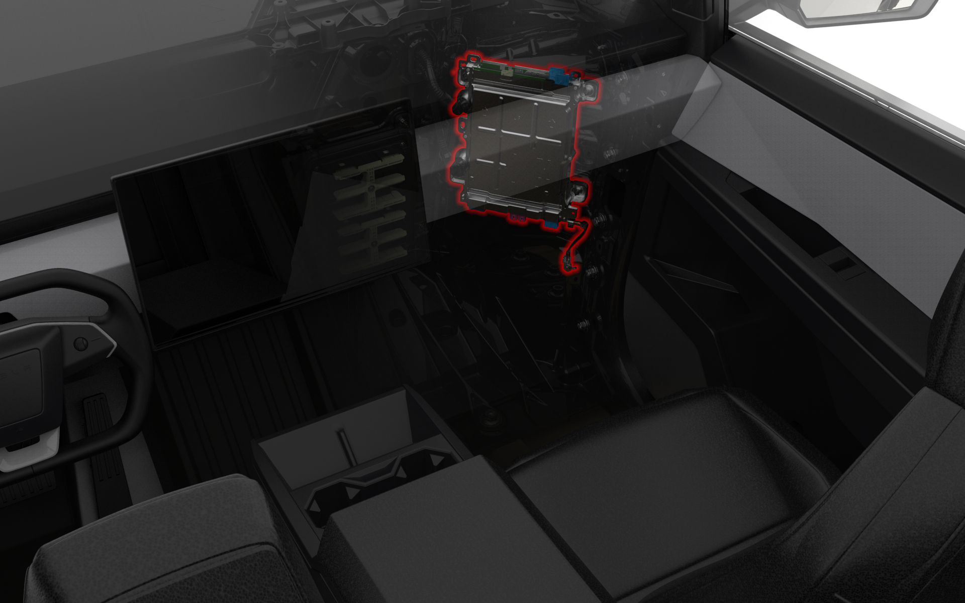
The Infotainment board is located in the Car Computer, which is mounted in a portrait orientation to the right front casting reinforcement in the cabin behind the Glove Box.
 |
|---|
| Car Computer Location |
 |
|---|
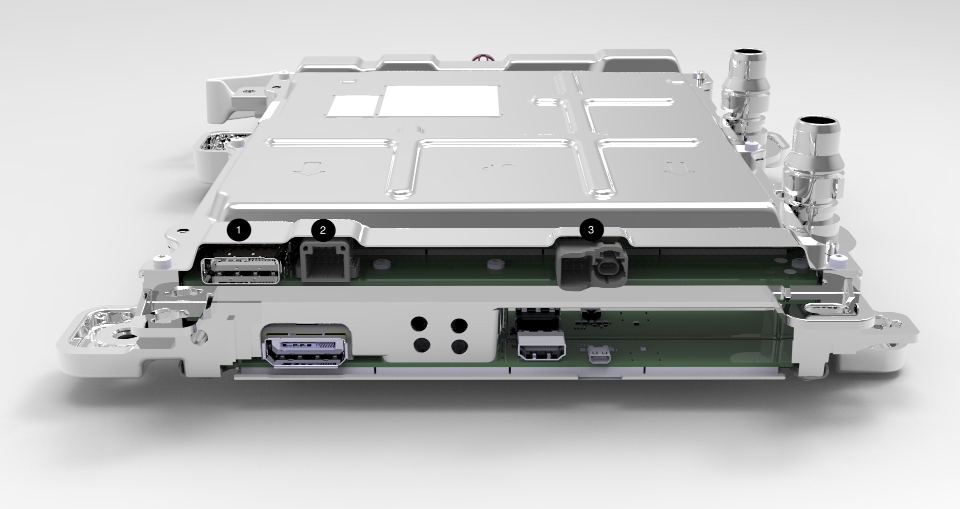
| 1. Vehicle Controller Right Power / High Voltage Battery Ethernet / Radio Tuner Ethernet 2. Instrument Panel Audio 3. Telematics Control Unit ( Power / Ethernet / A2B ) |
| Connector View Top |
 |
|---|
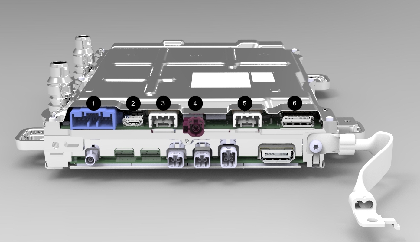
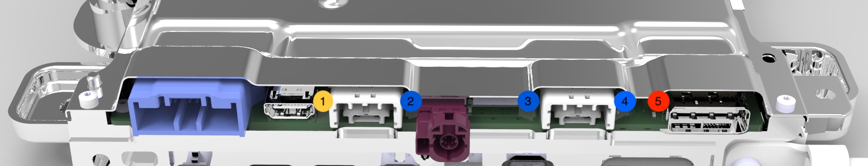
| 1. Diagnostic Ethernet / Ethersnoop / Onboard Diagnostic & Restraint Control Module CAN / Sleep Bypass Voltage 2. Debug (Not Connected to Vehicle Harness) 3. Glove Box USB 4. Rear Display Power / Ground / Communication 5. Center Display Power / Ground / Communication 6. Vehicle Controller Right Power / Etherloop |
| Connector View Bottom |
There are several new connectors on the Infotainment board, including the Signal & Power Universal Device Connector (SPUD), the Automotive grade USB-C connector as well as the Driver's Assistance Board to Board Connector.
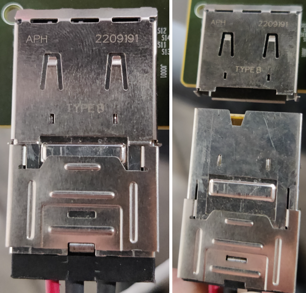
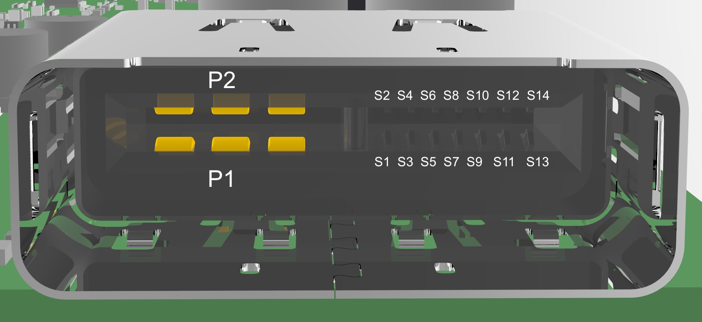
- Signal Power and Ground Universal Device Connector(SPUD): The board utilizes two different SPUD connectors: Type A and Type B. Each connector has specific keying, which will only allow for connection to the matching female connector. These connectors are not serviceable. Each SPUD has 16 pins. P1 and P2 carrying 48V power and ground with the remaining 14 pins carrying a mix of ground and signal wires.
 |
|---|
| Type A |
 |
|---|
| Type B |
 |
|---|
| Female Signal Power Universal Device Connector |
- Automotive Grade USB-C: The Automotive Grade USB-C is essentially just a USB-C connector with a special housing that allows the connector to be locked in place. Just like any USB-C, the connector allows for 24 pins, four power, four ground, and the remaining 16 for data transfer. This connector is not serviceable.
 |
|---|
| Automotive Grade USB-C |
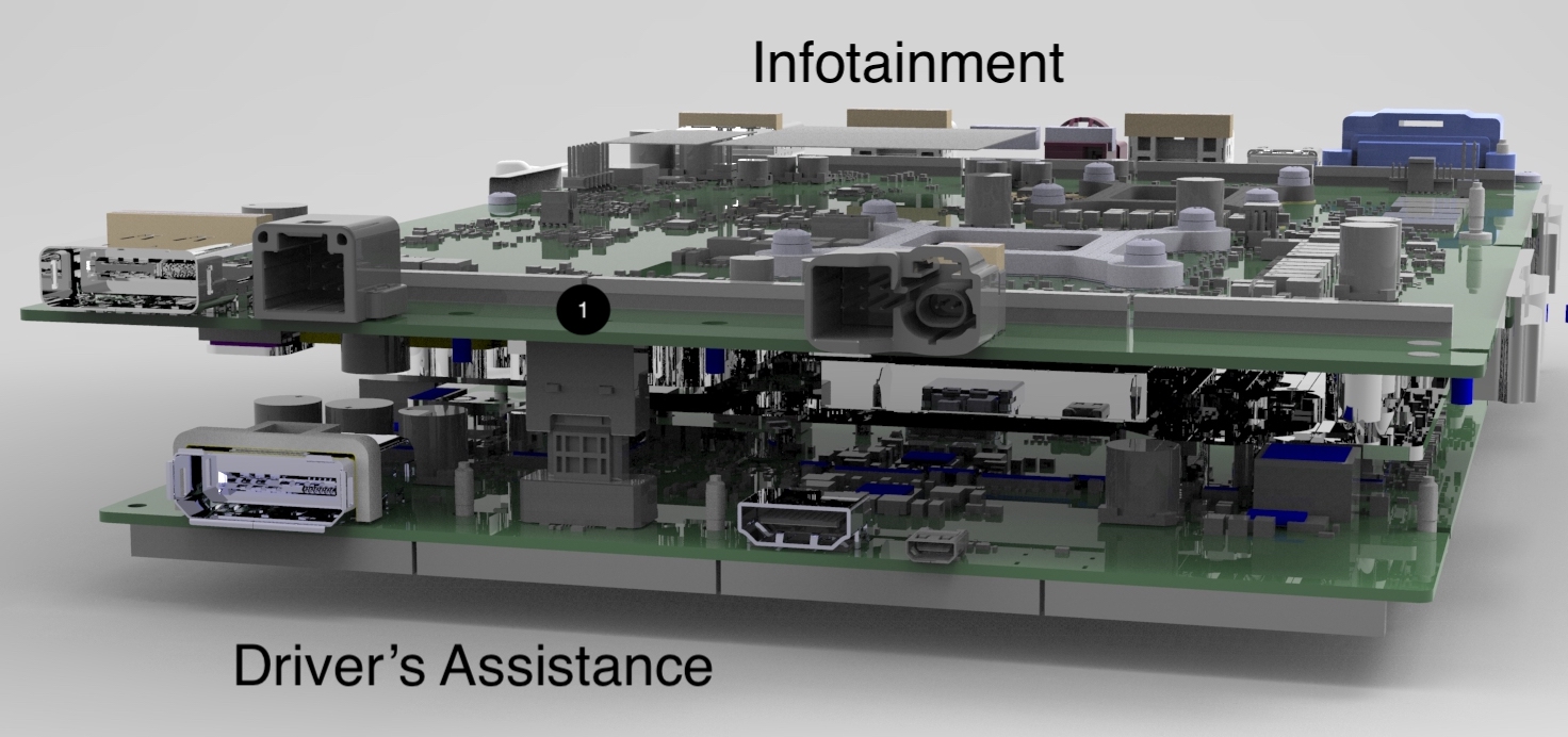
- Drive's Assistance Electric Control Unit Board to Board Connector: This connection is not visible on the exterior of the Car Computer since it is a female end sitting on the bottom of the Infotainment board and mounts to the bottom of the Driver's Assistance ECU. This connector is not serviceable.
 |
|---|
| Driver's Assistance Electric Control Unit Board to Board Connector |
| 1. Driver's Assistance Board to Board Connection |
Power States - The Infotainment board uses the Advanced Configuration and Power Interface (ACPI) standard for power control. The standard defines six power states S0-S5. However, the Infotainment board only uses three of them: S0, S3, and S5. These states define power usage levels of hardware at a given time.
-
S0 (Working State) - In this state, the system is awake and operational. The operating system is booted and applications are running. All hardware is consuming power.
-
S3 (Sleep) - This is a sleep state where most components are powered off but volatile memory (DDR) is kept powered on. When transitioning back to S0 (working state), applications and processes are able to continue where they left off as their last working state are still being stored in the powered volatile memory.
-
S5 (Soft Off) - This is the shutdown state. Most hardware is powered off. Since volatile memory is not powered in this state, the previous application and process states will be lost, and a full boot sequence is required to return to S0.
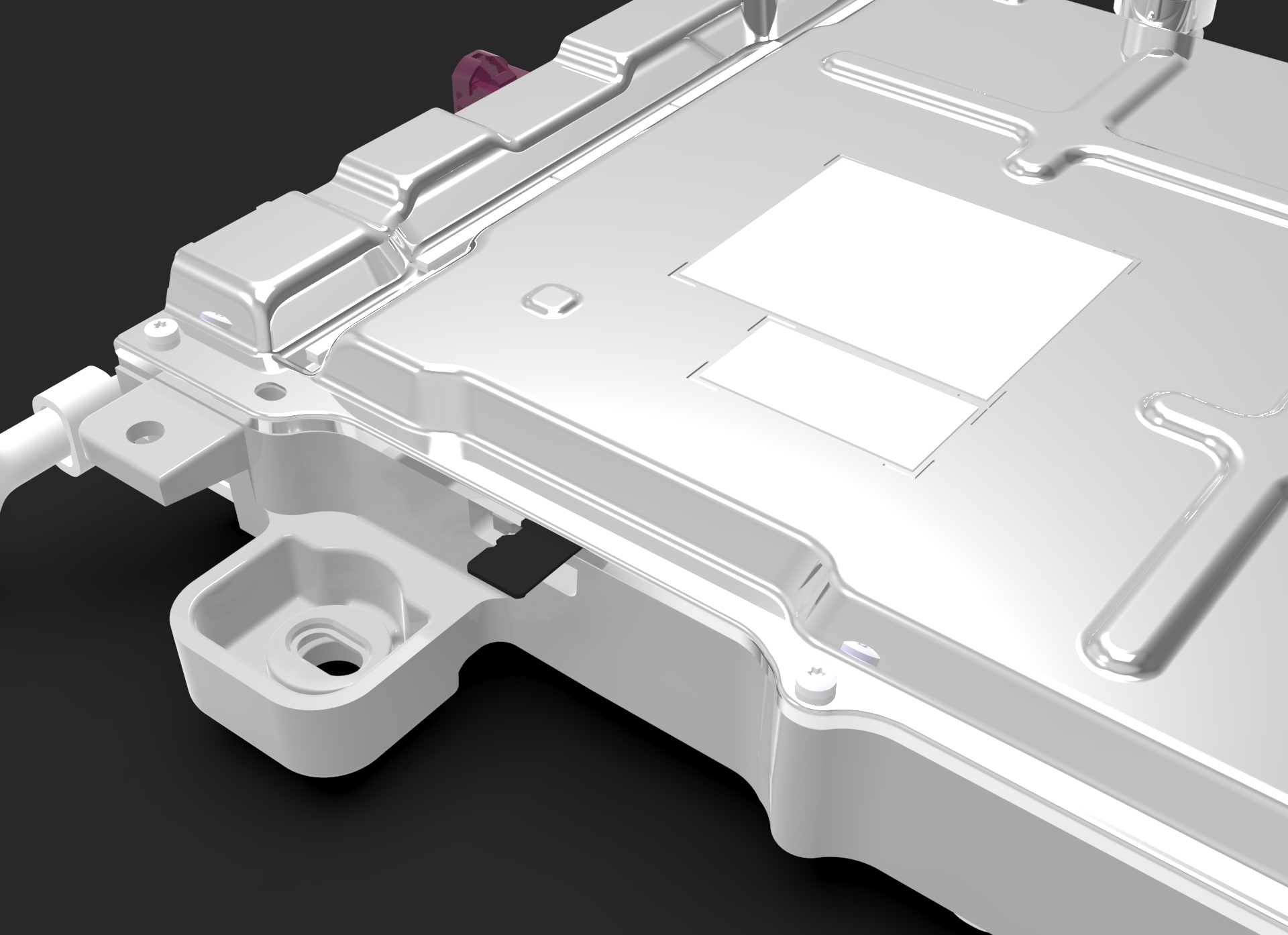
The only component of the Infotainment board, which can be serviceable separately, is the 16 GB Gateway Micro SD Card. This card is located on the lower right side of the Infotainment board and has a provision in the Car Computer frame, which allows for access to the Micro SD Card.
 |
|---|
| Gateway Micro SD Card |
Communication
-
Ethernet Switch: The Serial Gigabit Media Independent Interface (SGMII) is a serial interface standard used for Gigabit Ethernet connections, primarily connecting a Media Access Control (MAC) device to an Ethernet Physical Layer (PHY) device, allowing for data transfer rates of 1 Gbit/s.
-
Gateway: Universal Asynchronous Receiver/Transmitter (UART) is a communication protocol that enables full-duplex communication over a serial line. As a non-synchronized method, there is no shared clock signal between the transmitting and receiving devices, which means that both must agree on the data rate before communication begins. The data is sent as individual bytes, with start and stop bits to indicate the beginning and end of each byte.
System on Chip (SoC)link
Overviewlink
- The AMD Ryzen Embedded V1807F with Radeon Vega Gfx chip serves as the central processing unit (CPU) with integrated graphics (GPU). The SoC handles computational tasks and system control. The processor interprets and executes instructions from the system's software while managing data flow between memory and peripherals, ensuring efficient power management as well.
Specificationslink
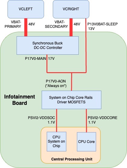
- Power - Power is provided to the System on Chip from VCRIGHT (VBAT-SECONDARY) or VCLEFT (VBAT-PRIMARY), both operating at 48V. This voltage is subsequently reduced to 17V by a DC/DC controller energizing the P17V0-MAIN power rail. This main 17V power rail then merges with the 13V sleep bypass voltage (P13V0BAT-SLEEP), resulting in the 17V "Always On" power rail (P17V0-AON). This power supply energizes the System on Chip Core Rails Driver-MOSFETs. The MOSFETs output 1.1V to both the CPU's core and System on Chip. The SoC & Core Driver-MOSFTs will each send a power good signal indicating each power rail has stabilized. These two signals are combined to produce the SOC-PWR-PGOOD, which is logged by the Gateway as the signal GTW_BMP_PGOOD_PIN.
 |
|---|
| CPU Power |
Operationlink
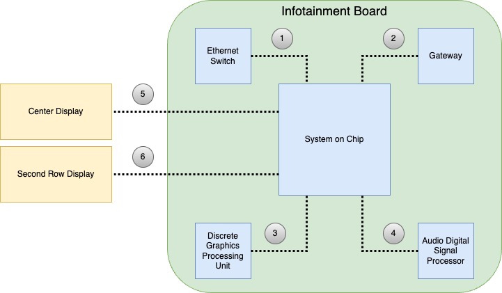
Communication - The System on a Chip (SOC) communicates with the Ethernet Switch through a direct Serial Gigabit Media Independent Interface (SGMII). It interfaces with the Gateway using a direct Universal Asynchronous Receiver/Transmitter (UART) line. Additionally, the SOC communicates with the discrete Graphics Processing Unit (dGPU) via the third-generation Peripheral Component Interconnect Express (PCIe Gen 3), operating at a speed of 8Gb/s per lane, across 8 lanes. For the Display, the SOC utilizes a Display Port 2.0 display data interface, while for the Rear Display, it uses a High-Definition Multimedia Interface (HDMI) data interface. Additionally, the SOC communicates with the Audio Digital Signal Processor (ADSP) through USB and Time Division Multiplexing.
-
Discrete Graphics Processing Unit (dGPU): The third-generation Peripheral Component Interconnect Express (PCIe Gen 3) is a high-speed interface standard used in various hardware connections, offering 8 Gb/s per lane across 8 lanes. It allows for bidirectional communication between devices, making it suitable for high-performance graphics processing tasks.
-
Display Interfaces: The Center Display interfaces with the System on Chip over Display Port 2.0, which offers support for high resolutions, refresh rates, and color depths, making it suitable for advanced displays. The Second Row Display interfaces with the System on Chip using High-Definition Multimedia Interface (HDMI) which is sent over a serializer/deserializer part. HDMI is a well-known standard that provides video and audio transmission over a single cable, commonly used in modern TVs and monitors.
-
Audio Digital Signal Processor (ADSP): Universal Serial Bus (USB) offers a standardized connection for peripheral devices, while Time Division Multiplexing (TDM) is a method that transmits multiple signals or data streams over a single channel. The combination of USB and TDM in communication with ADSP allows for efficient audio data management and ensures synchronization between various audio components.
 |
|---|
| 1. Direct Serial Gigabit Media Independent Interface (SGMII) 2. Universal Asynchronous Receiver/Transmitter (UART) 3. Third-generation Peripheral Component Interconnect Express (PCIe Gen 3) 4. USB and Time Division Multiplexing 5. Display Port 2.0 6. High-Definition Multimedia Interface (HDMI) |
| System on Chip Communication Diagram |
Thermal - The AMD Ryzen System on Chip is designed to operate at a maximum temperature of 105° C. Symptoms of a malfunctioning CPU could include subpar or unpredictable UI performance, spontaneous rebooting, or a blank Center Display. These issues may arise due to the Car Computer overheating, which will activate built-in alerts meant to identify CPU throttling and extreme temperatures.
Alerting
- UI_a150_infoCPURunningHot - This alert is triggered when the signal UIS_cpuTemperature reaches 89°C, indicating the car computer is running too hot, and the user may begin to experience a performance reduction.
- UI_a151_carComputerThermalProblem - This alert triggers when the CPU temperature difference to coolant is greater than 30, indicating a potential hardware condition affecting performance.
- UI_a152_infoThrottling - When the CPU temperature is at 92° C, the CPU frequency will be throttled. The UI may seem to lag (low refresh rate) at this point.
Signals
- GTW_SOC_BIOS_BOOT_OK - Indicates the status System on Chip's Basic input/Output System (BIOS) boot. One indicates the BIOS is booted, and zero indicates the BIOS is not booted.
- GTW_SOC_OS_BOOT_OK - Indicates the status of the System on Chip's Operating System Boot. One indicates that the Operating System is booted, and zero indicates not booted.
- GTW_tempNearSoC - Temperature in Celsius taken from a temperature sensor near the System on Chip.
- GTW_PSVI2_VDDSOC - Indicates 1.1V Voltage reading coming out System on Chip Driver-MOSFETS. "VDD" is a term used in digital electronic indicating a positive volta0ge supply. Power supply to the non-core parts of the CPU.
- GTW_PSVI2_VDDCORE - Indicates 1.1V Voltage reading coming out System on Chip Core Driver-MOSFETS. Power to the CPU core which is responsible for actual reading and executing of instructions.
- GTW_BMP_PGOOD_PIN - Indicates that power to the System on Chip Core Rails Driver-MOSFETs are good.
- UI_cpuTemperature - Temperature of the System on Chip.
- UI_readyForDrive - Indicates that the critical processes of the user interface such as telltale information, audio, and updater status are all ready for drive.
- UI_powerManagerState - Reflects the state of the user interface power manager. Useful for determining if the UI is using high power or entering/exiting sleep. There are 18 possible states.
Gatewaylink
Overviewlink
The gateway, a critical part of the vehicle's operating system, is a microcontroller with three CPUs and substantial memory resources. It contains two 160MHz 32-bit CPUs, one 80MHz 32-bit CPU, 6 MB of flash memory, and 768 KB of RAM. It is the backbone of the infotainment system and beyond and is responsible for routing the CAN data that allows various parts of the vehicle to communicate with each other.
Its features include an on-chip Non-Volatile Random Access Memory (NVRAM) that stores the vehicle's configuration data, and a microSD card that records selected CAN signal data. It also has the capacity to control and identify the vehicle's required states, and ensure the secure fetching and distribution of updates for each module. Furthermore, the gateway has a role in the system booting process, choosing the kernel bank to start the User Interface (UI).
One of its other important functions is to process touch data from the display and forwards it to the UI (Touch via Gateway), enhancing the interaction between the driver and the vehicle.
Power - The System on Chip (SoC) is powered by either VCRIGHT (VBAT-SECONDARY) or VCLEFT (VBAT-PRIMARY), both of which operate at 48V. This initial voltage is reduced to 17V by a DC/DC controller, which energizes the P17V0-MAIN power rail. Subsequently, this main 17V power rail combines with a 13V sleep bypass voltage (P13V0BAT-SLEEP) to form the 17V "Always On" power rail (P17V0-AON).
Voltage is then reduced via a synchronous buck converter to power the 3.3V P3V3-MAIN rail. P3V3-MAIN is then spliced to form P3V3-GTW, which serves as the Gateways 3.3V power supply and power supply for two load switches. One load switch is enabled when the Gateway boots into its application then powers the 3.3V P3V3-SD rail powering the Gateway's Micro SD Card Reader. The other emerges from the load switch as 1.2V P1V2-GTW serving as the Gateways 1.2V power supply.
 |
|---|
| Gateway Power |
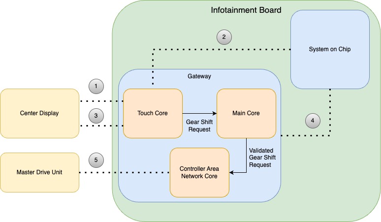
Touch via Gateway - Cybertruck does not use a traditional stalk to select drive gears. Instead, primary gear selection is done via touchscreen by analyzing touch data. This is accomplished by routing touch-reliant data from the touchscreen over I2C to the Gateway's CPUs for analysis then sending it over UART to the Ryzen. The touchscreen is connected to the Gateway via a I2C Bus.
When touch is asserted, the touchscreen sends an interrupt via the touch interrupt line. Once Gateway sees the interrupt, touch data can be retrieved over the I2C bus. Gear shift requests are first analyzed by the Gateway's touch core, then validated by the Gateway's main core and sent to the CAN core where they leave the Gateway to the master drive inverter.
 |
|---|
| 1. Touch Interrupt 2. Universal Asynchronous Receiver-Transmitter (UART) 3. Inter-Integrated circuit (I2C) 4. Inter-Integrated circuit (I2C) 5. Controller Area Network (CAN) |
| Gateway Touch Gear Shift Validation |
Alerting
-
GTW_w138_sdCardEndOfLife - The Gateway microSD card has reached or is approaching the end of its expected lifetime and should be replaced. The microSD card may enter read-only mode, which would prevent logging and vehicle software updates.
-
GTW_w051_sdCardFileSystemFailure - Gateway detects its microSD card file system has become corrupted and needs to be formatted. Software updates will be unavailable. Previously stored logs will be lost due to file system corruption.
-
GTW_w050_sdCardInitFailure - Gateway cannot initialize its microSD card, which may indicate the microSD card is not installed correctly or needs to be replaced. Software updates will be unavailable. Previously stored logs will be lost due to file system corruption.
-
GTW_w117_unexpectedDestructiveResetStatus - An unexpected vehicle gateway (GTW) reset occurred due to a reason not listed in the GTW software, which can occur after a loss of low voltage (LV) power, among other reasons.
Signals
-
GTW_P3V3_MAIN - The voltage of the 3.3V Main Power Rail.
-
GTW_mc_rgm_des - Signal from the Reset Generation Module internal to the Gateway details the type of destructive reset performed. A destructive reset source is associated with an event related to a critical (usually hardware) error or dysfunction.
-
GTW_mc_rgm_fes - Signal from the Reset Generation Module internal to the Gateway details the type of functional reset performed. A ‘functional’ reset source is associated with an event related to a less-critical (usually not hardware) error or dysfunction.
Graphics Processing Unitlink
The System on a Chip integrates an AMD Radeon Vega iGPU, which aids in rendering the User Interface, video playback, and gaming.
Power - The power is supplied by both primary and secondary 48V power sources, which is routed through a reverse voltage protection circuit, then stepped down by a DC-DC converter to 17V (P17V0-GPU).
 |
|---|
| Graphics Processing Unit Power |
Operationlink
Communication - dGPU communicates with the SOC via the third-generation Peripheral Component Interconnect Express (PCIe Gen 3) at a pace of 8Gb/s per lane, utilizing 8 lanes. It also has an Inter-Integrated circuit (i2c) connect to the Gateway and communicates with the Center Display over Display Port 2.0.
 |
|---|
| 1. Display Port 2.0 2. Inter-Integrated circuit (i2c) 3. Third-generation Peripheral Component Interconnect Express (PCIe Gen 3) |
| Discrete Graphics Processing Unit Communication Diagram |
Alerting
- UI_a128_dgpuNotDetected - will assert if a malfunction or communication link issue preventing communication to the SOC.
- UI_a129_dgpuOperationFailure - will assert if the dGPU is communicating with the SOC, but this communication reveals errors that will prevent normal operation.
- UI_a168_dgpuPowerOnSelfTestFailure - will assert if the dGPU fails a Power-On Self Test (POST) or a series of diagnostics tests that are run to ensure that the system's hardware is functioning properly.
Audio Digital Signal Processorlink
The ADSP is located on the Infotainment board inside the Car Computer and is designed specifically for processing digital signals. A digital signal is a sequence of numbers that represent physical quantities such as sound. ADSPs are optimized for high-speed numeric processing, and they excel at tasks like filtering noise out of signals and compressing audio. Cybertruck is equipped with a single ADSP with two cores and an Arm Cortex-A5 processor that has access to 2 Gigabytes DDR3 Memory.
Power - Power is provided to the Audio Digital Signal Process from VCRIGHT (VBAT-SECONDARY) or VCLEFT (VBAT-PRIMARY), both operating at 48V. This voltage is subsequently reduced to 17V by a DC/DC controller energizing the P17V0-MAIN power rail. This main 17V power rail then merges with the 13V sleep bypass voltage (P13V0BAT-SLEEP), resulting in the 17V "Always On" power rail (P17V0-AON).
Voltage is then reduced via a synchronous buck converter to power the 3.3V PV3V3-BKUP rail. Power from the P3V3-BKUP rail then enters a load switch enabled by the Gateway and emerging as P3V3-ADSP. The P3V3-ADSP is spliced to power a load switch for the base amplifier as well as two step down converters, one for ADSP and one for the ADSP's DDR Memory. The DDR Memory power rail is logged by the Gateway as "GTW_P1V5_ADSP_DDR3".
 |
|---|
| Audio Digital Signal Processor Power |
Communication - ADSP communicates directly with the Etherloop Switch and the Ethernet Switch via a Reduced Gigabit Media-Independent Interface (RGMII) supporting up to 1000 Mbps. It interfaces with the Gateway using a direct Universal Asynchronous Receiver/Transmitter (UART) line. It also communicates with two Automotive Audio Bus (A2B) Transceivers, one of each A2B bus, A2B-A and A2B-B via I2C and Time Division Multiplexing (TDM). Communication to the System on Chip is done via USB2 and Time Division Multiplexing.
 |
|---|
| 1. USB2 / Time Division Multiplexing 2. Reduced Gigabit Media-Independent Interface (RGMII) 3. Reduced Gigabit Media-Independent Interface (RGMII) 4. Universal Asynchronous Receiver/Transmitter (UART) 5. Inter-Integrated Circuit(I2C) / Time Division Multiplexing (TDM) 6. Inter-Integrated Circuit(I2C) / Time Division Multiplexing (TDM) 7. Inter-Integrated Circuit(I2C) / Time Division Multiplexing (TDM) |
| Audio Digital Signal Processor Communication |
Signals
- GTW_adspPingState - Ping state from Gateway to the ADSP. Valuable for determining whether the ADSP is booted and communicating with the Gateway.
- GTW_adspPingSeqno - Ping sequence from the Gateway to the ADSP. This is an incrementing count that starts with GTW_adspPingState PING_OK and stops with PING_FAIL.
- GTW_P1V5_ADSP_DDR3 - Voltage readings from the Audio Digital Signal Processor's DDR Memory.
Infotainment Ethernet Switchlink
The purpose of the Infotainment Ethernet Switch is to provide a communication path between the Diagnostics Port, System on Chip, Gateway, Tesla Connectivity Unit, audio Digital Signal Processor, Driver's Assistance ECU, and Rail Tuner.
Power - Infotainment Ethernet Switch power originates from VCRIGHT (VBAT-SECONDARY) or VCLEFT (VBAT-PRIMARY), both operating at 48V. This voltage is subsequently reduced to 17V by a DC/DC controller energizing the P17V0-MAIN power rail. This main 17V power rail then merges with the 13V sleep bypass voltage (P13V0BAT-SLEEP), resulting in the 17V "Always On" power rail (P17V0-AON).
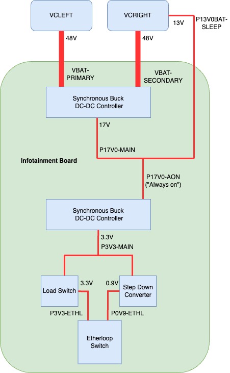
Voltage is then reduced via a synchronous buck converter to power the 3.3V P3V3-MAIN rail. This P3V3-MAIN rail voltage is fed into a load switch, which is enabled by the Gateway and exits as P3V3-ETH. The P3V3-ETH rail then enables a step-down converter, which steps down the P3V3-MAIN rail to 0.9V powering the P0V9-ETH rail. P3V3-ETH provides 3.3V power and P0V9-ETH provides 0.9V power to the switch. These power rails are logged by the Gateway as GTW_P0V9_ETH and GTW_P3V3_ETH.
 |
|---|
| Infotainment Ethernet Switch Power |
Communication - The Infotainment Ethernet Switch enables communication between the System on Chip and the Driver's Assistance Electronic Control Unit at a speed of 2.5 Gigabits per second (2.5/Gbps) using High-Speed Gigabit Media Independent Interface (HSGMII). Communication to the Audio Digital Signal Processor and Gateway is obtained with separate Reduced Media Independent Interface (RMII) connections. The Ethernet switch also communicates directly with the Telematics Control Unit (TCU) via 1000B-TI, the Diagnostics port via 100B-TX, and the Radio Tuner over 100B-T1.
 |
|---|
| 1. 100B-TX 2. Reduced Media Independent Interface (RMII) 3. High-Speed Gigabit Media Independent Interface (HSGMII) 4. 1000B-TI 5. High-Speed Gigabit Media Independent Interface (HSGMII) 6. 100B-T1 7. Reduced Media Independent Interface (RMII) |
| Infotainment Ethernet Switch Communication |
Alerting
- GTW_w101_switchWatchdog - Triggered when the System on Chip does not respond to ping from the Gateway for 10 Seconds. Will reset the Ethernet Switch in an attempt to restore communication.
- GTW_w116_switchInitFailed - Indicating that the Ethernet Switch has failed to initialize.
Signals
- GTW_P0V9_ETH - 0.9V power supply to the Ethernet Switch.
- GTW_P3V3_ETH - 3.3V power supply to the Ethernet Switch.
Etherloop Switchlink
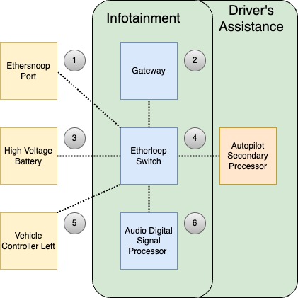
In the Infotainment board, Etherloop Switch connects the Infotainment board to the Etherloop. It is a critical node in the loop bridging the Vehicle Controller Left Etherloop Switch to the Autopilot Secondary Processor Etherloop Switch. The Etherloop Switch is the same chip used for the Ethernet Switch and the path to power is very similar.
Power - Etherloop Switch power originates from VCRIGHT (VBAT-SECONDARY) or VCLEFT (VBAT-PRIMARY), both operating at 48V. This voltage is subsequently reduced to 17V by a DC/DC controller energizing the P17V0-MAIN power rail. This main 17V power rail then merges with the 13V sleep bypass voltage (P13V0BAT-SLEEP), resulting in the 17V "Always On" power rail (P17V0-AON).
Voltage is then reduced via a synchronous buck converter to power the 3.3V P3V3-MAIN rail. This P3V3-MAIN rail voltage is feed into a load switch which is enabled by the Gateway and exits as P3V3-ETHL. The P3V3-ETHL rail then enables a step-down converter which steps down the P3V3-MAIN rail to 0.9V powering the P0V9-ETHL rail. P3V3-ETH provides 3.3V power and P0V9-ETHL provides 0.9V power to the switch.
 |
|---|
| Etherloop Switch Power |
Communication
The Etherloop communicates with the Vehicle Controller Left (VCLEFT) and the Autopilot Secondary Processor (APS) using 1000B-T1, and communicates with the Ethersnoop using 100B-TX and the High Voltage Battery using 100B-T1. Communication with the Audio Digital Signal Processor and the Gateway are realized by separate Serial Gigabit Media Independent Interface (SGMII) connections.
 |
|---|
| 1. 100B-TX 2. Serial Gigabit Media Independent Interface (SGMII) 3. 100B-T1 4. 1000B-T1 5. 1000B-T1 6. Serial Gigabit Media Independent Interface (SGMII) |
| Etherloop Switch Communication |
Signals
- GTW_ethlCanTx - Total number of CAN messages transmitted on the etherloop bus by the gateway.
- GTW_ethlCanRx - Total number of CAN messages received by the gateway on the etherloop bus.
- GTW_ethlFrameRx - Total number of etherloop frames received by the gateway.
- GTW_ethlFrameTx - Total number of etherloop frames transmitted by the gateway.
- GTW_ethlFrameErrorsTx - Total number of errors encountered when transmitting etherloop frames.
- GTW_ethlFrameErrorsRx - Total number of errors encountered when receiving etherloop frames.
- GTW_ethlSeqErrorsRx - Total number of etherloop frame sequence receive errors. Also known as Frame Check Sequence (FCS) errors encountered while performing the Cyclic Redundancy Check (CRC) check during reception of an Ethernet frame.
- GTW_ethlParseErrorsRx - Total number of etherloop frame parse receive errors. Parse errors can occur when the Ethernet Frame is corrupted or not properly structured according to the Ethernet protocol.
- GTW_ethlDrvVLANPktRx - Total number of Ethernet packets with vlan tags received on the etherloop interface.
- GTW_ethlDrvVLANPktsTx - Total number of Ethernet packets with vlan tags transmitted on the etherloop interface.
Alerting
- GTW_w303_ethloopSwitchPort2LinkDown - The vehicle Gateway (GTW) detects that the port 2 (Dedicated to Vehicle Controller Left) of the etherloop switch has a link down when in drive, indicating a condition affecting the cabling or the electronic control unit (ECU) connected to port 2.
- GTW_w304_ethloopSwitchPort3LinkDown - The vehicle Gateway (GTW) detects that the port 3 (Dedicated to the Autopilot Secondary Processor) of the etherloop switch has a link down when in drive, indicating a condition affecting the cabling or the electronic control unit (ECU) connected to port 3.
Nonvolatile Memory Express (NVMe)link
The Infotainment board contains 128Gb of Nonvolatile Memory Express (NVME) Storage. Non-Volatile means that the memory does not require power to retain data. Data stored in the vehicles NVMe will not clear when the vehicle is power cycled. Express means the storage uses a Peripheral Component Interconnect Express (PCIe) interface; this interface is favorable for its high bandwidth and low latency furthering fast read and write speeds. This storage is dedicated to the operating system, applications, user data, virtual (swap) memory, map data as well as Linux system and process logs.
Power - Nonvolatile Memory Express power originates from VCRIGHT (VBAT-SECONDARY) or VCLEFT (VBAT-PRIMARY), both operating at 48V. This voltage is subsequently reduced to 17V by a DC/DC controller energizing the P17V0-MAIN power rail. This main 17V power rail then merges with the 13V sleep bypass voltage (P13V0BAT-SLEEP), resulting in the 17V "Always On" power rail (P17V0-AON).
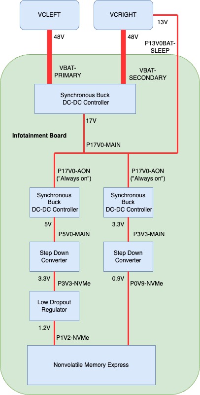
Voltage is then reduced via a synchronous buck converter to power the 3.3V P3V3-MAIN rail and 5V P5V0-MAIN rail. The P5V0-MAIN rail enters a step-down converter enabled by the system on chip and exits as the P3V3-NVMe rail. P3V3-NVMe powers low drop out regulator that exits as 1.2V to power the P1V2-NVMe rail and enable the step-down converter which drops P3V3-MAIN to 0.9V powering the P0V9-NVMe rail.
Both P0V9-NVMe and P1V2-NVMe directly power the NVMe and are logged in the Gateway as GTW_P0V9_NVME and GTW_P1V2_NVME respectively.
 |
|---|
| NVMe Power |
Communication - NVMe communicates with the System on Chip exclusively via Third-generation Peripheral Component Interconnect Express (PCIe Gen 3).
Storage partitioning - The Nonvolatile Memory of the Infotainment Board is partitioned into several block devices or devices that store or hold data (files and directories) in blocks. These block device partitions can be viewed with the ODIN task PROC_ICE_X_INFO-LIST-DISK-PARTITION.
Alerting
- UI_a119_nvmeBlockDeviceMissing - NVME block devices can not be accessed which could result in an inability to read or write date.
- UI_a120_nvmePCIeLinkErrorDetected - PCIe link errors due to misconfigurations or non-zero error counters can result in data corruption on the NVMe PCIe link.
- UI_a146_nvmeNeedsReplacement - NVMe is no longer functional and will require Car Computer replacement.
Signals
- GTW_P0V9_NVME - 0.9V power supply to the NVMe.
- GTW_P1V2_NVME - 1.2V power supply to the NVMe.
Memory (DRAM)link
Overviewlink
The Infotainment board contains 16 GB DDR4 Double Data Rate Synchronous DRAM (Dynamic random access memory) for Trucks which also have a dGPU. Trucks without a dGPU contains 8 GB of DDR4. DDR4 Memory is a type of volatile memory, it requires power to retain data. When Car Computer is power cycle this memory will be cleared out. This memory is used by the CPU and iGPU to store data and instructions that need to be accessed quickly.
Communication DDR4 Memory communicates directly with the system on chip over a direct channel.
Virtual Memory - This memory management technique implemented by the operating system allows system processes to use more memory than is physically available in the form of RAM (volatile memory). The system achieves this by apportioning sections of NVMe SSD (non-volatile memory) to serve as an extension of RAM. This reserved space, known as swap space, is used to temporarily hold data that is not currently in use by the system, effectively enhancing the system's overall memory capacity.
Resident Memory - This is the portion of system memory that is occupied by a process and cannot be swapped out to disk (non-volatile memory) but remains 'resident' in the RAM (volatile memory). It represents the actual physical memory or RAM, consumed by a process during its execution.
Out Of Memory (OOM) Killer - The Out of Memory Killer is a feature of the Linux Kernel which deploys when the system runs critically low on memory. It attempts to stabilize memory usage by selectively terminating less critical processes in order to keep the system running. In some cases, a system reset is required to resolve the loss of memory. This will result in a kernel panic.
Serviceabilitylink
When a software or hardware issue occurs with memory, the User can experience symptoms related to slow performance, crashing, freezing, and high CPU usage. The UI also has access to set alerts and signals which can indicate a software or hardware issue with memory.
Alerting
- UI_a116_UncorrectableMemoryError - Uncorrectable memory errors were reported by the memory controller. These type of errors may lead to a system reboot and indicate a hardware or software issue.
- UI_a142_CorrectableMemoryError - Correctable memory errors were reported by the memory controller. Does not lead to a system reboot and could indicate a hardware or software issue triggered frequently.
- UI_a167_CgroupOverMemKill - A process was killed by its control group for exceeding its memory limit. The killed process id will report in the logged signal data for this alert.
- Signals
- UIS_bluetoothMemUsage - Bluetooth Resident Memory usage in MB.
- UIS_dashcamviewerMemUsage - Dashcam Viewer's Resident Memory usage in MB.
- UIS_gpsmanagerMemUsage - GPS Manager's Resident Memory usage in MB.
- UIS_mediaserveMemUsage - Media Server's Resident Memory usage in MB.
- UIS_nuanceserverMemUsage - Nuance Server's Resident Memory usage in MB. This is the process responsible for User Interface vocalization of navigation turn-by-turn directions and text messages.
- UIS_odinMemUsage - Onboard Diagnostic Interfaces’ Resident Memory usage in MB.
- UIS_qtcarMemUsage - Qtcar's Resident Memory usage in MB. Qtcar is the main graphical user interface process.
- UIS_radioserveMemUsage - Radio Server's Resident Memory usage in MB.
- UIS_serverMemUsage - Resident Memory usage of the process that manages the User Interface's network resources.
- UIS_speechrecoMemUsage - Resident Memory usage of the process responsible for speech recognition in MB.
- UIS_teslachromiumMemUsage - Resident Memory usage of the browser in MB.
- UIS_tmserverMemUsage - Resident Memory usage of the Tesla Maps Server in MB.
- UIS_valhallaserverMemUsage - Resident Memory usage of the navigation rerouting engine.
- UIS_videodMemUsage - Resident Memory usage of the process which handles camera feeds in MB.
- UIS_systemMemSwapUsage - Usage of (NAMe) non-volatile memory dedicated to act as RAM (volatile memory) for the entire system.
- UIS_uiQtCarSwapUsage - Usage of (NAMe) non-volatile memory dedicated to act as RAM (volatile memory) for the main graphical user interface process.
- GTW_P1V2_MEM_VDD_S3 - 1.2V rail for SOC memory in S3 (sleep) state.
- GTW_P2V5_MEM_VPP_S3 - 2.5V rail for SOC memory in S3 (sleep) state.
Diagnostic LEDslink
The Infotainment board has the ability to visually communicate the status of several internal power rails as well as heartbeats and debug states. These LEDs can be seen without removing the top cover of the Car Computer.
Specificationslink
Diagnostic LEDs differ based on Infotainment board revisions.
 |
|---|
| Diagnostic LED Location REV-C |
| 1. D12001 | Amber | 5V Power Rail for Glove Box USB (P5V0-USB0-FLT) |
| 2. D1033 | Blue | 12V Power Rail for Second Row Display (P12V0-Display 3) |
| 3. D1097 | Blue | System on Chip Power Good Signal (SOC-PWR-GOOD) |
| 4. D1025 | Blue | 12V Power Rail for Center Display (P12V0-Display 1) |
| 5. D1043 | Red | 3.3V Power Rail for Gateway SD Card (P3v3-SD) |
Operationlink
The following list provides details of the Infotainment board Diagnostic LEDs.
| State | Diode | Status |
|---|---|---|
| Working State (S0) | D12003 | Not Illuminated |
| D1033 | Illuminated for 9s, then off for 1s | |
| D1097 | Illuminated | |
| D1025 | Illuminated | |
| D1043 | Illuminated |
| State | Diode | Status |
|---|---|---|
| System on Chip Running in Recovery Mode | D12003 | Not Illuminated |
| D1033 | Illuminated | |
| D1097 | Illuminated | |
| D1025 | Illuminated | |
| D1043 | Illuminated |