Drive Unitslink
Last updated: October 20, 2023
Overviewlink
The drive unit contains a motor, gearbox, and drive inverter.The component parts of the assembly are highly integrated in order to reduce system complexity and improve reliability. The Rear Drive Unit assembly is attached to the rear sub-frame by front and rear gearbox mounts that are integrated into the gearbox case, and a third mount bolted onto the Motor housing. The Front Drive Unit assembly is mounted to the body by a Torque Reaction Arm bolted to the Motor Housing and a mount bolted onto the gearbox housing.
Warning
Follow all high voltage safety requirements anytime the drive unit is part of a vehicle repair. The Drive Unit contains 1.2mF of internal capacitance, enough to be lethal if the internal discharge functions are not working properly. Always use a multimeter to confirm that no dangerous voltage is present on the DC input connector of the drive inverter.
All motors must have a changing magnetic field to generate torque and induce rotation. Brushed motors do this by mechanically switching wire coils on and off as the rotor spins. Induction motors do not have brushes; instead, they use electrical waveforms to vary the magnetic fields in the motor and create torque.
The drive inverter converts the Direct Current (DC) from the battery pack into three Alternating Current (AC) phases in the stator. The current waveforms are 120° out of phase with each other and create a rotating magnetic field in the stator. This stator field induces current in the rotor. The induced rotor current creates a second magnetic field that opposes the stator field, producing motor torque. The speed of the motor depends on the frequency of the AC supplied by the drive inverter. The torque of the motor depends on the amplitude of the AC.
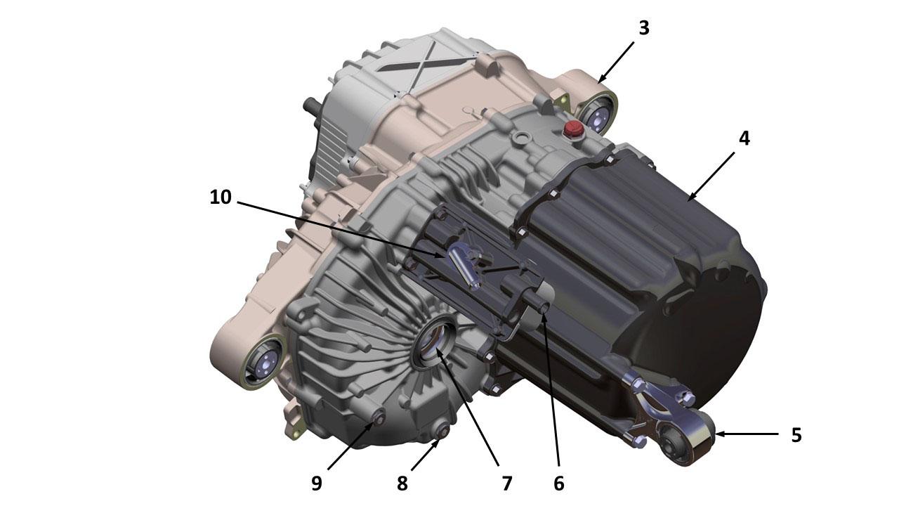
 |
|---|
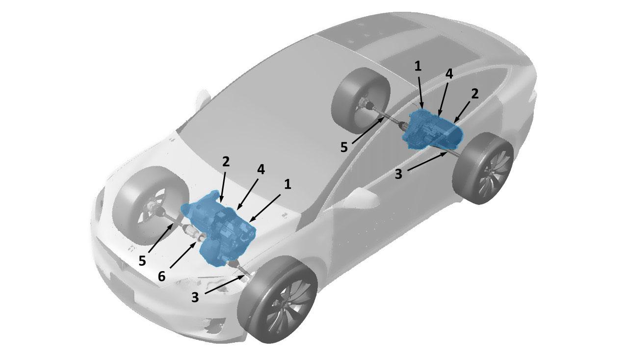
| 1. Drive inverter 2. Motor 3. Driveshaft LH 4. Gearbox 5. Driveshaft RH 6. Jackshaft (Front RH only) |
| Front/Rear Drive Unit - Location |
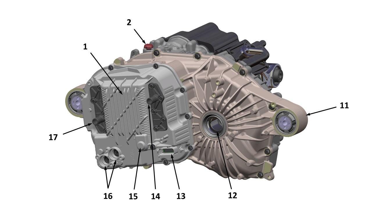
Drive Unit Mounts/Coolant Hose Connections/ High and Low Voltage Connectionslink
 |
|---|
 |
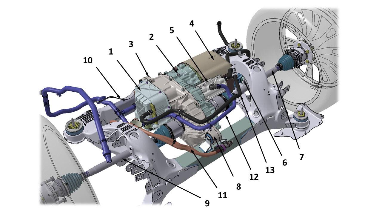
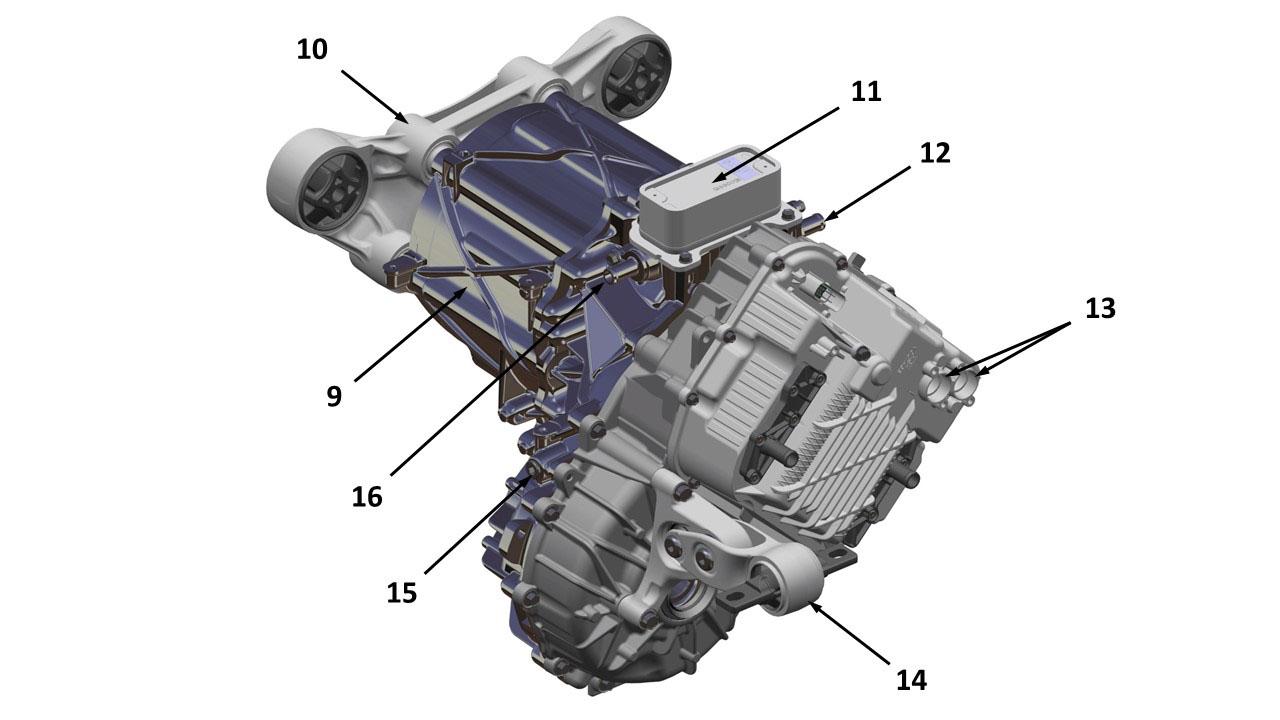
| 1. Drive inverter 2. Gearbox breather 3. Gearbox rear mounting 4. Motor 5. Coolant heat exchanger 6. LH side motor mount 7. Driveshaft LH 8. Gearbox front mounting 9. Driveshaft RH 10. Ground Strap 11. High Voltage cables 12. Coolant inlet 13. Coolant outlet 14. RH Motor Mount 15. Jackshaft |
| Front Small Drive Unit - Mounting and Connections |
Drive Unit Componentslink
 |
|---|
 |
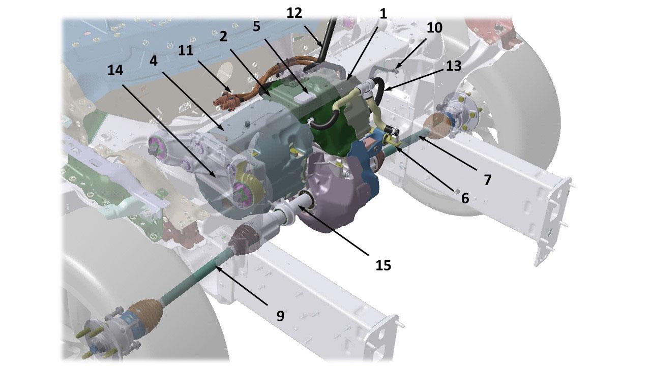
| 1. Drive inverter 2. Gearbox breather 3. Gearbox rear mounting 4. Motor 5. Motor speed sensor 6. Coolant manifold 7. Coolant inlet 8. Side motor mounting 9. Coolant pipe 10. Gearbox cooler 11. Gearbox front mounting 12. Gearbox output RH 13. Coolant outlet 14. Low voltage logic connector 15. High voltage cable connection cover 16. High voltage cable inlet |
| Large Drive Unit - Components |
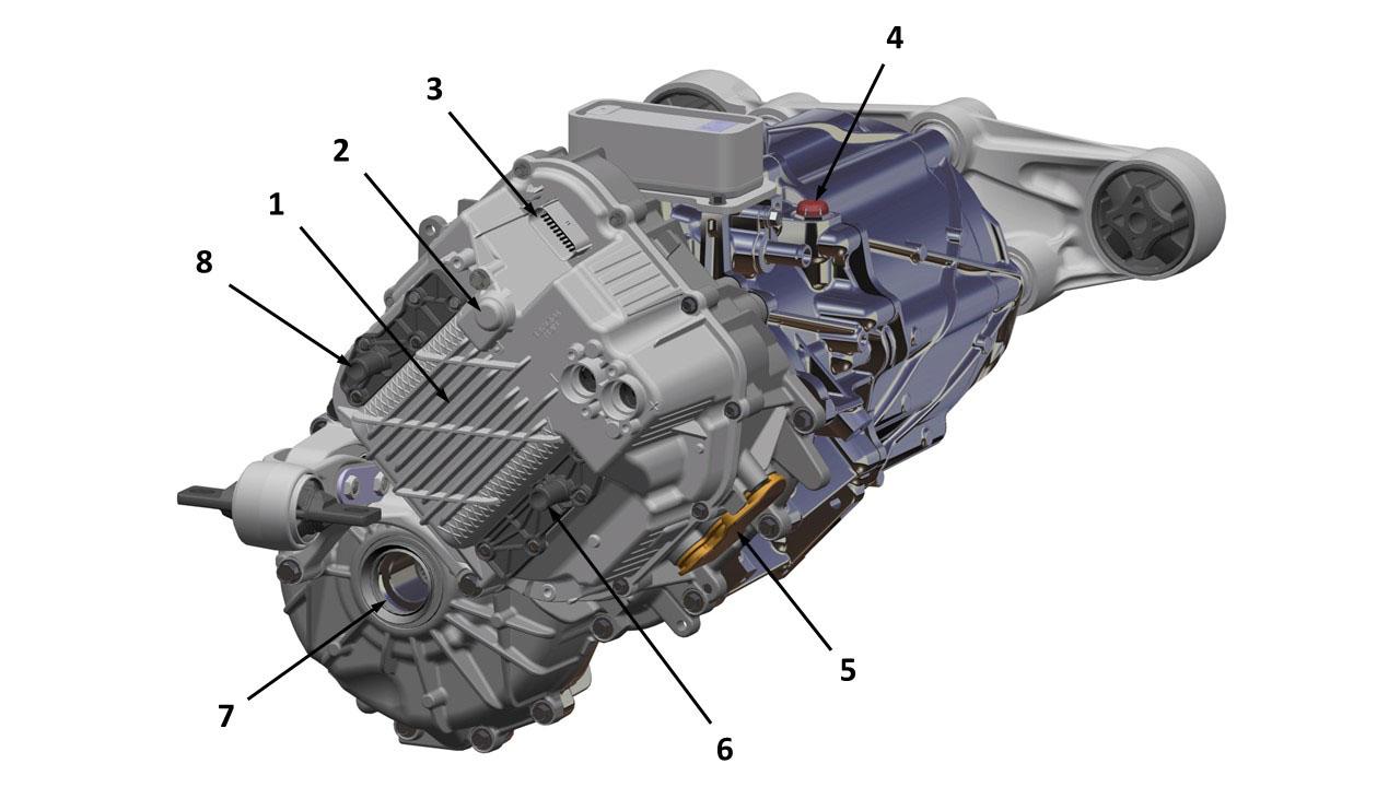
 |
|---|
 |
| 1. Drive inverter 2. Gearbox breather 3. Gearbox rear mounting 4. Motor 5. Side motor mount 6. Heat exchanger coolant outlet 7. Gearbox output LH 8. Gearbox fluid drain plug 9. Gearbox fluid fill plug 10. Heat exchanger coolant inlet 11. Gearbox front mounting 12. Gearbox output RH 13. Low voltage logic connector 14. Inverter coolant outlet 15. Inverter breather 16. High voltage connectors 17. Inverter coolant inlet |
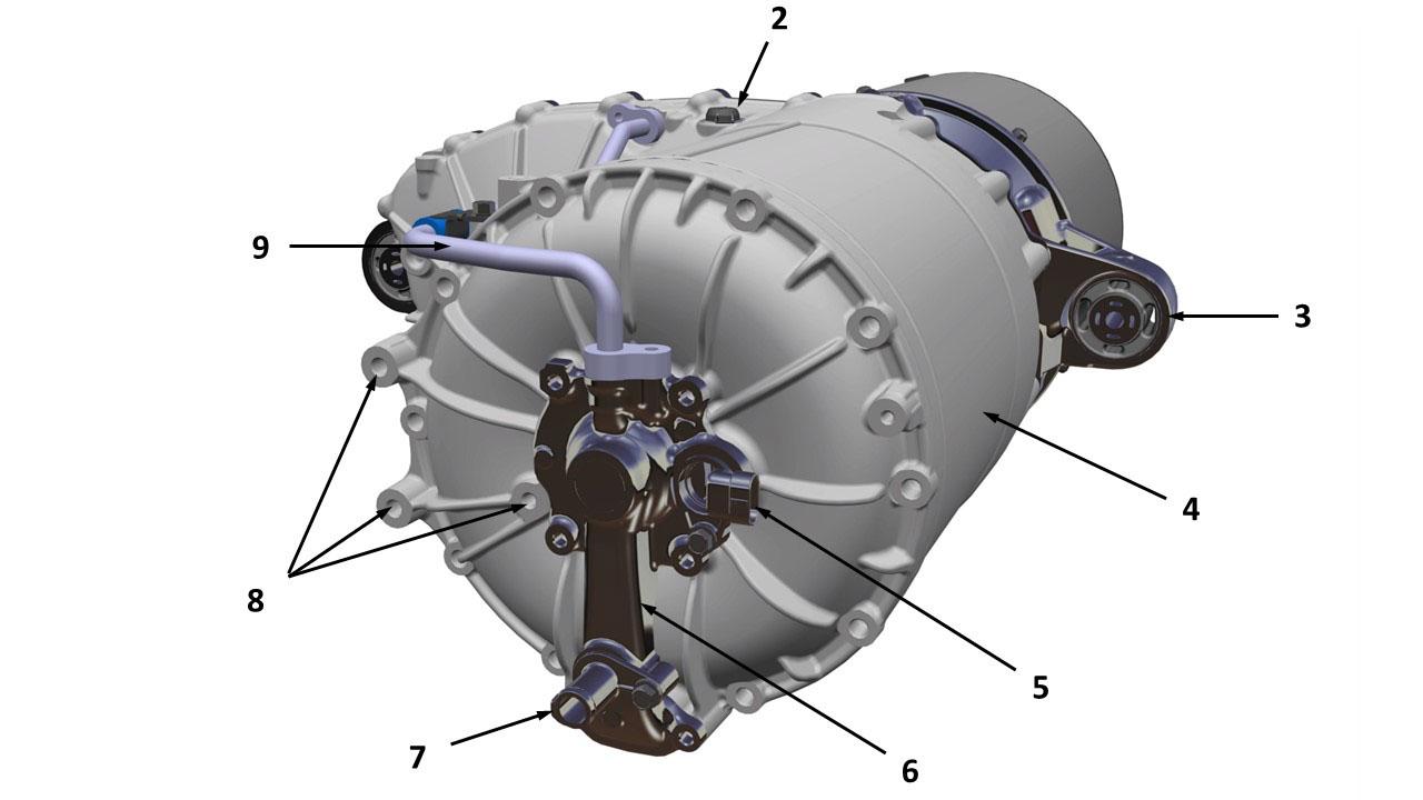
| Rear Small Drive Unit - Components |
 |
|---|
 |
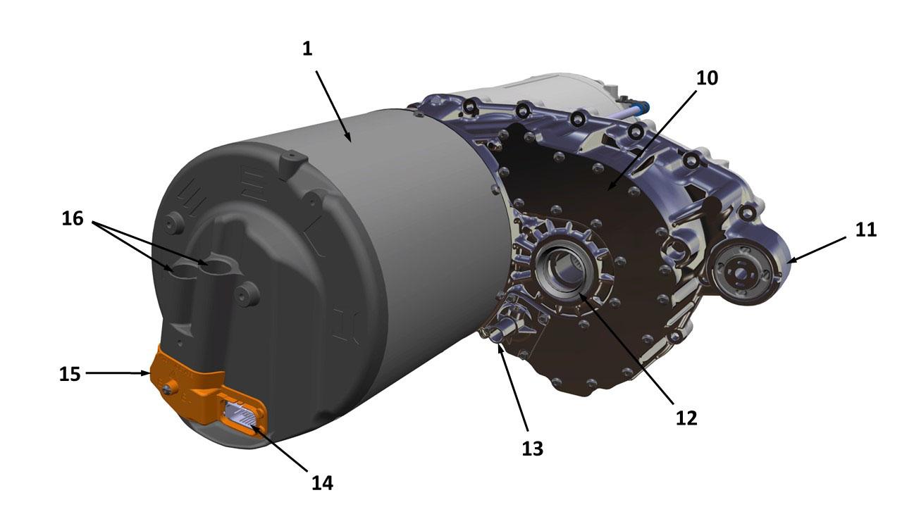
| 1. Drive Inverter 2. Inverter breather 3. Low voltage logic connector 4. Gearbox breather 5. Inverter output busbar cover 6. Inverter coolant inlet 7. Gearbox output LH 8. Inverter coolant outlet 9. Motor 10. Right Motor Mount 11. Heat exchanger 12. Heat exchanger coolant inlet 13. High voltage connectors 14. Left motor mount 15. Gearbox fluid fill plug 16. Heat exchanger coolant outlet |
| Front Small Drive Unit - Components |
Drive Inverterlink
Overviewlink
The Drive Inverter translates driver commands from the gear selector, accelerator, and brake pedal into alternating currents that are applied to the motor to generate the correct speed, torque, and direction of rotation to move the vehicle. The drive inverter is a bi-directional system, converting battery current to motor current – with current flowing in either direction and output torque in either direction. Regenerative braking is achieved using the drive inverter to produce negative torque and corresponding current flow from the motor to the battery. Regenerative braking is only allowed when the stability control and ABS systems are active. Traction control is implemented in the stability control system in Model X, with torque limiting commands sent to the drive inverter when traction is reduced.
The drive inverter contains two Digital Signal Processors (DSPs) on the control board. The main processor controls the motor, monitors the health of the Drive Unit system, and processes driver requests. The second processor, referred to as the Pedal Monitor, is a processor that can stop all torque and power generation if the motor currents, speed, or accelerator pedal conditions indicate that the main processor is not operating correctly. A Field Programmable Gate Array (FPGA) on the control board manages a variety of hardware level logical functions and protection circuits. The two DSPs and the FPGA can be reprogrammed over the CAN interface and communicate to each other over Serial Peripheral Interface (SPI) bus. The Gate Drive Unit (which is on a physically different board in the Large Drive Unit) will increase signal voltage and current (from approximately 5 to 12 volts) so that the control circuits on the Power Stage may operate. The Power Stage uses these signals and HV Battery power to output the desired voltage and current to the three Stator phases. An electrically erasable programmable Read-Only Memory (EEPROM) on the controller stores the serial number of the Drive Unit, allowing the pedigree and build history to be tracked.
Description and Operationlink
The drive inverter monitors the temperatures of the motor and power electronics. It sends cooling requests for the motor, gearbox and inverter electronics to the thermal controller. There is no direct control over the coolant flow or fan speeds from the drive inverter; the thermal controller manages the system to targets that are optimized for range and efficiency. If thermal limits are exceeded, the drive inverter limits motor torque until the temperatures are back within nominal operating range.
The front drive inverter is a slave to the master rear drive inverter. The master calculates the required torque for both front and rear, along with cruise control, traction control and torque split, which is then sent to the slave as an output torque request. The slave does not have accelerator or brake pedal inputs, so relies on Powertrain CAN bus signals to check for errors with the master, avoiding erroneous operation.
Behaviorslink
Gear Selectionlink
The gear selector stalk forms part of the Steering Column Control Module (SCCM) located on the steering column. The SCCM sends high-speed 500 kBd chassis CAN signal to the Tesla Gateway depending on the selected gear: P, R, N, or D. The CAN signal is then relayed to the drive inverter through the high-speed powertrain CAN at 500 kBd.
Neutrallink
Select Neutral and apply the parking brake if the vehicle needs to be stationary for a period of time, such as at a traffic signal. When the vehicle is in Neutral, no torque is commanded to the motor. The brake must be used when shifting out of Neutral into Drive or Reverse.
When Neutral is selected, the vehicle transitions into electrical neutral and commands zero torque to the motor. The drive inverter enters standby mode.
Drivelink
Drive can be selected whenever the vehicle is stationary or moving forward. Drive can also be selected if the vehicle's reverse speed is less than 5 mph.
If the vehicle has been in Neutral for more than 1 second and the vehicle is moving at less than 5 mph, the brake pedal must be depressed in order to enter Drive or Reverse.
If Drive is selected from Neutral or Reverse when the vehicle is stationary and the accelerator pedal is depressed, no torque is commanded until the accelerator pedal is released.
If the vehicle has been in Neutral or Park for more than 1 second and the vehicle is moving at less than 0.5 mph, the brake pedal must be depressed and the accelerator pedal released in order to enter Drive or Reverse.
In European vehicles, an invalid gear selection causes the vehicle to shift into Neutral. For all other markets, an invalid gear selection does not change the active gear.
Reverselink
Reverse drive is selectable whenever the vehicle’s forward speed is less than 5 mph. The maximum speed in reverse is limited to 15 mph.
If Reverse is selected from Neutral when the vehicle is stationary and the accelerator pedal is depressed, no torque is commanded until the accelerator pedal is released.
Reverse motion is achieved by reversing the direction of motor rotation. If Reverse is selected when wheel speed indicates the vehicle is traveling at more than 5 mph in a forward direction, the gear selection is denied.
Parklink
The Electronic Park Brake (EPB) is engaged to prevent the vehicle from rolling. The EPB disengages automatically when shifting from Park to Drive, Reverse or Neutral.
The gearbox has no mechanical parking pawl.
Denied Gear Shift Requestslink
Any gear position can be selected at any time; however, inappropriate gear selections are prevented until the required conditions are met. An audible alert indicates an invalid gear selection.
Range Modelink
The Model X allows the user to select to enable Range Mode, which reduces the amount of energy consumed by the thermal management system and disables Torque Split. When Range Mode is on, the most efficient Drive Unit is used to produce drive torque, with the other unit used to supplement when the torque demand increases, or additional traction is required. Vehicle dynamics take precedence over this feature at all times, therefore, it may not be in full operation under all driving conditions.
When Range Mode is off, the thermal management system is fully operational to keep the occupants at the desired humidity and temperature, while maintaining the battery temperature within its nominal operating range. Range Mode reduces vehicle power consumption by modifying the thermal management strategies:
- It allows the HV battery to operate within a wider nominal temperature range, which reduces the energy consumed for cooling and heating of the battery.
- It restricts cabin heating and cooling capacity, which reduces energy used by the AC compressor, PTC heater, and blower motor.
Torque Splitlink
Torque Split is used when Range Mode is off, to mitigate NVH of the Front Drive Unit at slow speeds, but still allow fair overall vehicle efficiency when traveling at higher speeds. Vehicle dynamics take precedence over this feature at all times, therefore, it may not be in full operation under all driving conditions, including in cold climates when low traction surfaces are expected.
At low torque and low speed driving, the rear Drive Unit will be preferred for improved NVH. As the rear Drive Unit on performance variants is less efficient. At low torque and higher speeds, the front Drive Unit on performance variants will be preferred for greater efficiency. The transition between each is gradual from approximately 40-55 mph (65-90 km/h). When torque demand is high (i.e. outside the shaded bounds of the figure below), performance will take precedence and the unit(s) with traction available will be used.
Torque Managementlink
The traction control system reduces motor torque to reduce rear tire slip during acceleration and deceleration. Traction control operates by comparing tire speeds (as measured by the Anti-lock Braking System wheel speed sensors, vehicle longitudinal acceleration, motor speed and transmission gear). Traction control is automatically enabled every time the vehicle enters Drive. The vehicle monitors wheel speed and controls motor torque to minimize wheel slip.
If the vehicle is in Drive, torque is limited to avoid exceeding the motor’s maximum speed.
Unrestricted drive torque is available when:
- The system is in Drive mode.
- The battery and drive inverter status are both OK.
- The gear selector is in Drive or Reverse and the EPB is released.
Drive torque is restricted but available if:
- The battery and/or drive inverter temperatures are outside the defined limits.
- The drive inverter loses communication with the HV Battery.
- Motor temperatures are above full-power maximum allowable temperature.
- Traction control is active. Torque is limited to control wheel slip when required. This is true for drive torque and regenerative braking torque.
- The battery voltage is at a level where power usage under high torque demand causes the voltage to drop below the minimum allowable charge level. Torque is limited to ensure voltage stays in a safe range.
- The battery state of charge is at a level where the regenerative torque could cause the battery to exceed the maximum allowable voltage. Regenerative torque is limited to ensure cell voltages stay in a safe range.
Note
Prior to total loss of torque, the driver is informed via the touchscreen as torque is progressively limited.
Drive torque is restricted to zero torque (though not always immediately) when:
- The battery and/or drive inverter status is not OK.
- The EPB is engaged.
- Selecting gears.
- A gear selection request is denied.
If the brake pedal is pressed and held while the accelerator is pressed, an accelerator pedal override will reduce the maximum torque available. The Torque limit will vary depending on the order of pedal operation and Driver torque request.
Cruise Controllink
Cruise control enables a constant road speed to be maintained without using the accelerator pedal, compensating for road gradient and vehicle loading conditions. The system is useful on journeys where a constant speed can be maintained for long periods.
The cruise control system can be in one of four states:
- Off
- Standby
- Active
- Failsafe
Cruise control is operated using the control stalk on the left of the steering column. The stalk is a direct input to the steering column control module, which converts the signals it receives into CAN messages that it broadcasts on the chassis bus. The gateway module routes these messages to the drive inverter via the powertrain bus. The Drive Inverter controls motor torque according to the torque requests it receives from the cruise control.
The driver can perform several different actions with the control stalk:
- Single pull on: The driver pulls the cruise control stalk toward the steering wheel to toggle Traffic Aware Cruise Control (TACC). System ON is indicated by a blue icon on the Instrument cluster.
- Double pull on: The driver double pulls the cruise control stalk toward the steering wheel to toggle Traffic Aware Cruise Control (TACC) and Autopilot convenience features (if installed). System ON is indicated by 2 blue icons on the Instrument cluster (TACC and Autosteer).
- Tap the stalk up to the first detent and release immediately: Initializes set speed or increases the set speed by 1 mph increments. If vehicle speed is greater than set speed, the vehicle speed becomes the set speed.
- Tap the stalk up to the second detent and release immediately: Initializes set speed or increases the set speed by 5 mph increments. If vehicle speed is greater than set speed, the vehicle speed becomes the set speed.
- Hold the stalk up to the first or second detent: Initializes set speed and steadily increases the set speed by 2 mph/second until released.
- Tap the stalk down to the first detent and release immediately: Initializes set speed or decreases the set speed by 1 mph increments. If vehicle speed is less than set speed, the vehicle speed becomes the set speed.
- Tap the stalk down to the second detent and release immediately: Initializes set speed or decreases the set speed by 5 mph increments. If vehicle speed is less than set speed, the vehicle speed becomes the set speed.
- Hold the stalk down to the first or second detent: Initializes set speed and steadily decreases set speed by 2 mph/second until released.
- Pull the stalk toward the driver: Previous set speed is resumed. If no previous speed was set, it is initialized.
- Push the stalk away from the driver: The motor torque command tapers gracefully (soft cancellation), and the cruise control state transitions from active to standby. The set speed is retained in memory.
Other actions the driver can perform to influence cruise control operation are:
- Press the brake pedal: Instantly transitions from active to standby (hard cancellation), set speed is retained in memory.
- Press the accelerator pedal: If the accelerator pedal is pressed to a position that corresponds to a commanded torque that exceeds the torque commanded by cruise control, the torque appropriate for that pedal position is commanded.
- Move the gear shift lever: If cruise control is active, selecting any gear besides Drive causes it to transition to standby.
- Push Park or parking brake buttons: If cruise control is active, it transitions to standby. Applying the parking brake also clears the set speed from memory.
- Power down the vehicle: Exiting drive mode turns cruise control off.
If the cruise control state transitions from active to standby while attempting to meet a new set speed, speed is set to the current vehicle speed at the time of the transition. If the cruise control state transitions from active to standby while attempting to meet a resume speed request, the set speed does not change.
Vehicle speed changes should not take place at a rate greater than 2 mph/second. If the vehicle’s speed is less than the set speed and the vehicle speed does not increase for 4 seconds, cruise control transitions to standby. If set speed reaches a value below 20 mph for any reason, the set speed clears from memory and cruise control transitions to standby. If cruise control is active and any signal goes missing, or is determined as irrational such that cruise control functionality cannot be provided, it enters failsafe state. In this state, all driver inputs are ignored and a warning is shown on the Instrument Cluster.
Regenerative Braking (Regen)link
Regeneration operates on the principle that the electric motor can also act as an electrical generator. This places a load on the motor, which in turn provides an additional braking effect.
The amount of regen torque generated is dependent on vehicle speed, battery state of charge, and the accelerator pedal position. The pedal provides maximum available regen torque when fully released, then proportionally less as the pedal is depressed. The motor delivers zero regen torque when the accelerator pedal reaches its neutral torque position, which moves depending on driving and vehicle conditions.
Note
A failure of the ABS or ESP system disables regenerative braking. A notification is displayed on the touchscreen. Regen may also be reduced or disabled when the tires may be traction limited, such as in cold weather or during traction control events. Regen is limited or disabled if battery SOC is too high.
The drive inverter converts this torque command into the appropriate 3-phase voltage and current waveforms to produce the commanded torque in the motor in the most efficient way. The torque command can be positive or negative. When the torque is used to slow the vehicle, energy is returned to the HV Battery to store for later use.
The maximum regeneration braking profiles take speed and corresponding drag into account to aim for a target total vehicle deceleration rate, not an energy recovery target. Regeneration braking profiles are tailored to everyday driving conditions, and typically provide higher deceleration rates at lower speeds.
Gearboxlink
Overviewlink
The Drive Unit features a single speed gear reduction gearbox, located between the motor and the drive inverter. The gearbox uses a layshaft arrangement with two stage gear reduction.
There is no mechanical linkage between the gear selector and the gearbox. The gearbox gear set is in constant mesh. The gearbox has no mechanical neutral or reverse gear, and no parking pawl. Reverse drive is achieved by reversing the polarity of motor torque. Neutral is achieved by de-energizing the motor. The cast aluminum gearbox casing features a gearbox and inverter breather and oil fill/level and drain plugs.
 |
|---|
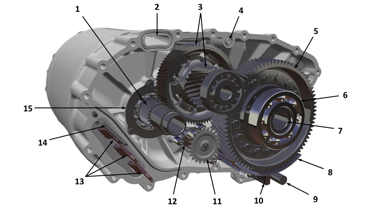
| 1. Input shaft gear 2. Coolant passage (stator to inverter) 3. Intermediate shaft 4. Coolant passage (coolant pipe to gearbox cooler) 5. Differential ring gear 6. Differential bearing 7. Differential carrier 8. Oil pickup baffle 9. Oil strainer 10. Oil pan magnet 11. Oil pump gear 12. Oil pump assembly 13. Stator phase input busbars 14. Stator temperature sensor wire harness 15. Input shaft retaining plate |
| Large Drive Unit - Gearbox |
 |
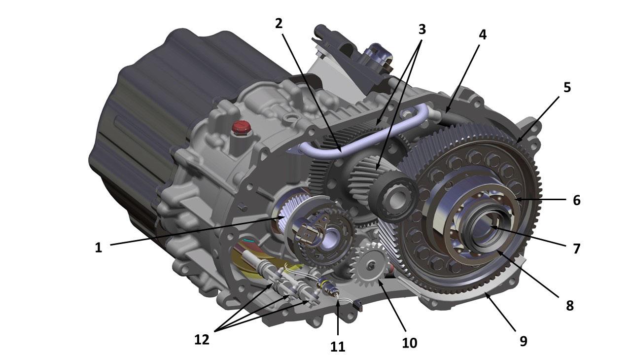
|---|
| 1. Rotor shaft input gear 2. Input shaft bearing 3. Transmission hose 4. Motor speed sensor 5. Oil pump assembly 6. Differential bearing 7. Differential carrier 8. Differential ring gear 9. Intermediate shaft 10. Motor encoder wheel |
| Front Small Drive Unit - Gearbox |
 |
|---|
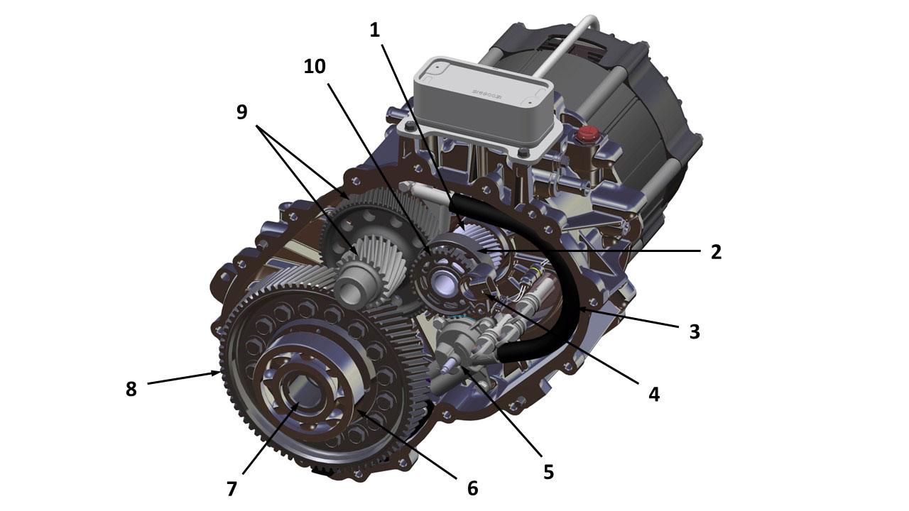
| 1. Rotor shaft input gear 2. Oil cooler pipe 3. Intermediate shaft 4. Transmission hose 5. Differential ring gear 6. Differential bearing 7. Differential carrier 8. Output oil seal 9. Oil pickup baffle 10. Oil pump gear 11. Stator temperature sensor wire harness 12. Stator phase input wire harnesses |
| Rear Small Drive Unit - Gearbox |
Output Gear (Differential)link
The open differential is of conventional design with the differential carrier bolted to the final drive ring gear. The housing supports the differential pin, side gears, and pinion gears. The differential assembly is supported in the gearbox assembly using deep groove ball bearings.
The differential allows the road wheels to turn at different speeds while providing an equal amount of torque. The integral spline on the output shaft meshes with the final drive gear on the differential assembly. When the output shaft rotates and the wheels are traveling at the same speed, torque is applied to the complete assembly; the pinion gear does not rotate. Torque is transmitted to the road wheels through the drive shafts. During cornering, the inner wheel travels a shorter distance at a lower speed. This results in the pinion gears rotating about the outer wheel side gear, therefore increasing the speed of the outer wheel.
Motor/Gearbox Cooling - Lubricationlink
The gearbox incorporates a positive displacement oil pump that is driven by the differential ring gear. The design of the gearbox allows for adequate lubrication when driving in reverse. Oil is scavenged from the bottom of the gearbox casing via a scavenge pipe and distributed to the gears and bearings. The scavenge pipe strainer is made from a wire mesh, to prevent solid contaminants from contacting the oil pump, gears and bearings. Following lubrication of the gears and bearings, any excess oil drains back to the bottom of the gearbox casing. A magnet in the sump, as well as magnetic drain plugs, entrap ferrous material to prevent entering the gear meshes or bearings.
In Small Drive Units (front and rear) the motor is also oil cooled. The gearbox oil after lubricating the gears it travels to the stator and rotor of the motor to cool them as well.
Motorslink
Overviewlink
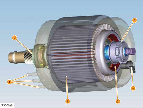 |
|---|
| 1. A, B, and C field windings 2. Rotor bearing 3. Motor encoder 4. Motor encoder sensor 5. Rotor 6. Stator |
| Large Drive Unit - Motor |
There are different types of motors to serve different purposes, but all of them follow the same principles. The torque in every electric motor is created is by two magnetic fields that interact to each other, causing forces that rotate the rotor. Depending on the way that the necessary magnetic fields are created, the motors are divided in different categories.
All Model S/X front and rear motors are asynchronous induction motor.
Motor Speed Sensor (Encoder)link
The motor speed is measured using a two-channel Hall Effect sensor. The sensor monitors the rotation of the teeth of the encoder wheel that is attached to the rotor shaft. The sensor output is two square waves that are 90 degrees out of phase from each other. The drive inverter control board uses the frequency of the encoder signal to determine motor speed, and the phase of the two signals to determine the motor direction.
The connection between the sensor and large drive inverter is external to the Drive Unit and routes through the rear subframe harness. The small Drive Unit sensor is located between drive inverter and gearbox housing and connected to the drive inverter by an internal wire harness. The drive inverter provides power to the motor speed sensor, as well as the ground return for the sensor. The Large Drive Unit motor speed sensor can be replaced in the field by unplugging the harness and removing the mounting screw, however the Small Drive Unit requires Inverter removal for access.
Cooling Systemlink
The Large Drive Unit motor, gearbox, and drive inverter share a common liquid cooling system. Coolant enters the motor side of the Drive Unit and flows through the gearbox and drive inverter through a series of internal tubes. The internal coolant loop is split into two flow paths by the Coolant Manifold on the motor end bell casting. Coolant from the bottom of the manifold is channeled into the stator cooling jacket in the housing. From the Stator, coolant flows through the drive inverter before exiting the drive unit through the coolant outlet. Coolant from the center of the manifold is sent to the rotor shaft, which is hollow. Coolant flows into the shaft via the Rotor coolant pipe, which is then returned to external coolant pipe and flows through the coolant pipe to the Gearbox cooler, then exits through the common coolant outlet.
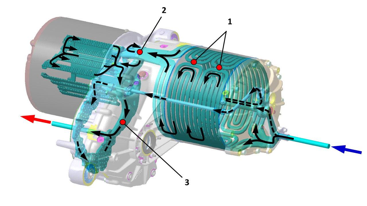 |
|---|
| 1. Stator temperature sensors (location shown for illustration purposes only) 2. Inverter inlet temperature sensor 3. Inverter outlet temperature sensor |
| Large Drive Unit - Coolant Circulation |
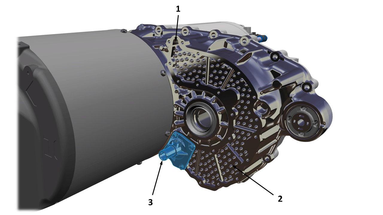 |
|---|
| 1. Gearbox cooler input 2. Gearbox cooler 3. Drive unit coolant outlet |
| Large Drive Unit - Cooling Components |
The Small Drive Unit motor and gearbox share a common liquid cooling system, using the gearbox fluid. A heat exchanger is then used to transfer this heat to Coolant, which also passes through the drive inverter in parallel. The coolant is a glycol/water mix that is circulated through the drive inverter and Heat Exchanger. Coolant passes from the radiator, through the charger(s), to the Drive Unit.
The Coolant is a glycol/water mix that is circulated by the drive unit cooling loop. Coolant passes from the radiator, through the charger(s), to the coolant manifold. Coolant returns to the radiator where the temperature of the coolant is reduced by air flowing across the radiator fins before it flows around the circuit again. The system operates at pressures between 5 psi (35 kPa) and 19 psi (130 kPa). System temperature is maintained below 85°C (185°F). See the Thermal Management Theory of Operation for further detail.
Halfshaftslink
The gearbox on large and small rear Drive Units are connected to the rear road wheels via two equal length halfshafts. The front Drive Unit features a Jackshaft on the right side of the Drive Unit to allow the use of equal length halfshafts. These halfshafts feature a Constant Velocity (CV) joint at both ends, each with a rubber boot to protect the joint from contamination. The outer CV joint features external splines that locate into the internally splined drive flange. The externally splined inner CV joints locate into the internally splined gearbox output shafts. A serviceable driveshaft seal is fitted to the gearbox casing on each side, to seal the casing and prevent the entry of dirt and moisture.
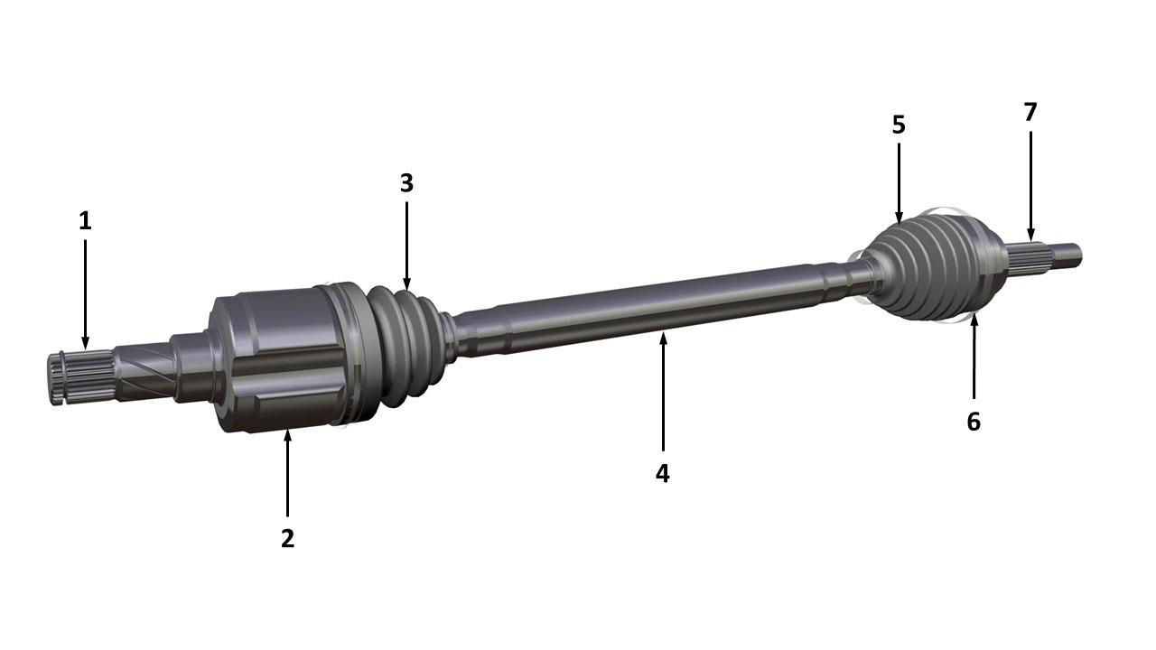 |
|---|
| 1. Outer CV joint 2. RH driveshaft 3. Inner CV joint 4. Jackshaft bearing 5. Jackshaft 6. Differential spline 7. Inner CV joint 8. LH driveshaft 9. Outer CV joint |
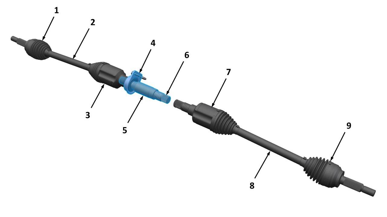 |
|---|
| 1. Differential spline 2. Inner CV joint 3. Inner CV joint boot 4. Driveshaft 5. Outer CV joint boot 6. Outer CV joint 7. Hub spline |