Power Conversion System 2 AC Conversionlink
Last updated: October 10, 2024
Overviewlink
Cybertruck is not only able to charge on Alternating Current (AC) but is able to supply AC voltage through the charge port and various power outlets built into the vehicle. Power is supplied from the High Voltage (HV) battery to electric appliances using 120V or 240V 60Hz AC, which is generated using a bidirectional Power Conversion System 2 (PCS2). Appliances are connected to Cybertruck using outlets inside the cabin or the bed or through the charge port using a new bidirectional Gen 2 Universal Mobile Connector (UMC) with a new UMC pigtail adapter that connects like an outlet to the UMC.
Compared to PCS1, PCS2 features a lighter and more compact design while still having increased power capability because of its bidirectional converter architecture.
This section focuses on the AC conversion aspect of PCS2 (AC-DC and DC-AC). Direct Current (DC) to DC conversion for Low Voltage (LV) support and HV bus precharge are covered in a different document.
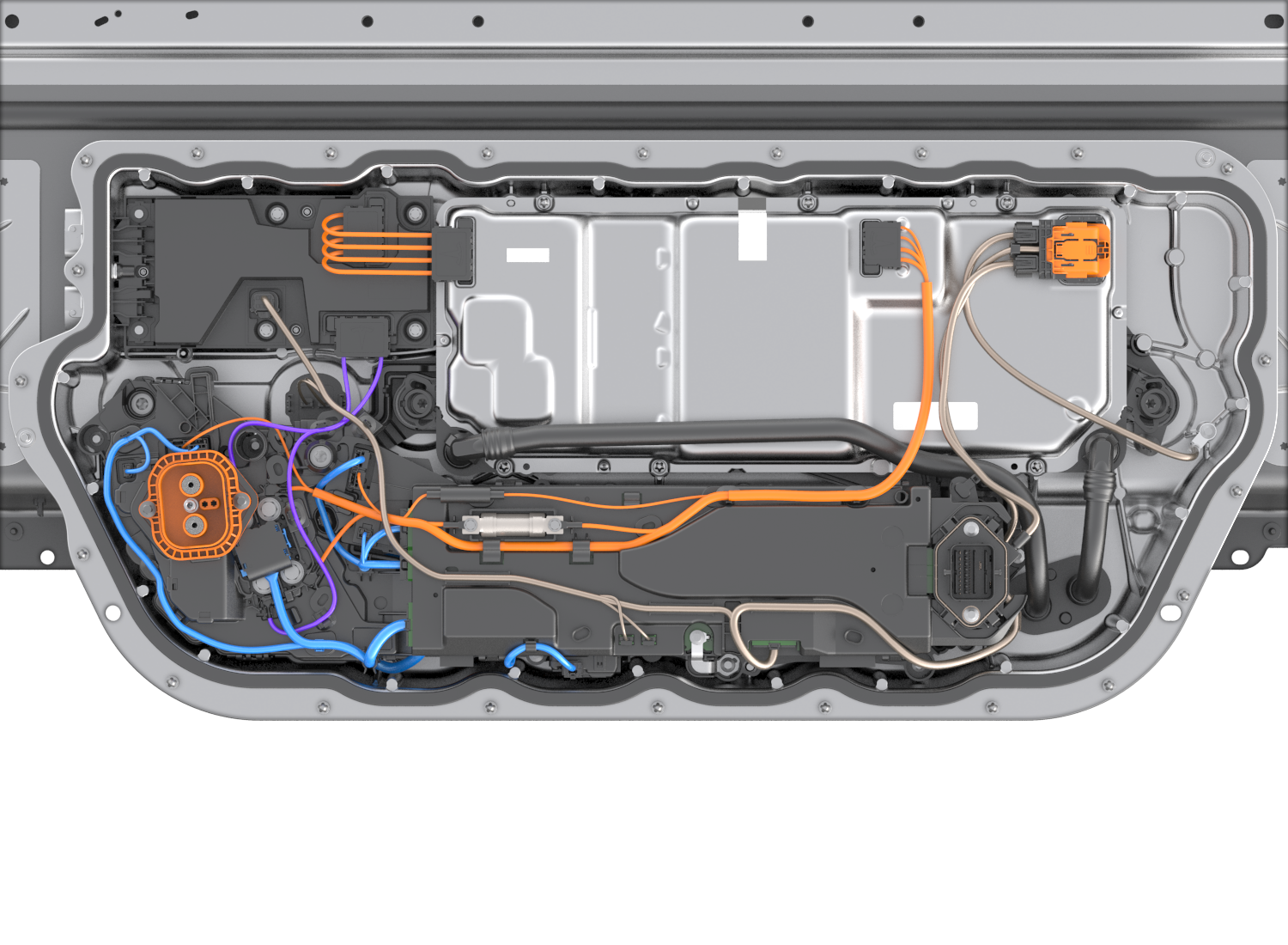 |
|---|
| Ancillary Bay With Power Conversion System In Top Right Corner |
Specificationslink
DC-DC Converterlink
- Number of DCDC converters: 2
- Low voltage: 24-58V
- Continuous power: 3kW
- Peak transient power: 6kW
AC-DC / DC-AC Converterlink
- Number of converters per AC line: 2
- AC voltage: 90-300 Vrms
- DC voltage: HV battery voltage range
- Continuous power: 11kW single-phase
Operationlink
Even as a single-phase charging system, PCS2 is equipped with 4 AC terminals for line 1, line 2, line 3, and neutral. These lines are necessary to be able to supply 120V and 240V to the various outlets of Cybertruck simultaneously while being able to AC charge from any AC power source in a wide voltage range.
To distribute AC power within the vehicle, the PCS2 AC terminals are connected to the AC Junction Box.
PCS2 receives its charge command from the High Voltage Processor (HVP) through the Controller Area Network (CAN) and a hardware enable line. Both signals need to match in order for PCS2 to start converting power. The requested power is commanded by the Battery Management System (BMS) over CAN.
Serviceabilitylink
If PCS2 does not operate as expected, it is important to determine if another condition is preventing the charge port from operating.
For example, the hardware signals from HVP can prevent PCS2 from charging. Further, if the BMS detects any issues with the HV battery, charging may be inhibited. The Charge Port (CP) may also block charging if the charge port latch is not engaged or the charging station is not communicating with the vehicle. In addition, the AC Junction Box, which is located between charge port and PCS2, features relays that need to close in order to allow current to flow from external charging equipment to PCS2. If one of these is malfunctioning, PCS2 will not be able to receive voltage. In these cases, an alert from HVP, BMS, or CP will be present, so generally it is a good idea to resolve all HVP, BMS, and CP alerts prior to resolving PCS2 issues.
Reduced or interrupted charging can in general be caused by low grid power quality (such as grid transients) or a charging station side issue. To rule out such issues, it is always recommended to perform a charging test at a different location (to rule out grid side issues) and/or with a different charging station (to rule out external charging equipment issues).
Reduced charging power can be caused by thermal system issues, leading to high internal PCS2 temperature.