Autopilot Hardware 1.0link
Last updated: December 17, 2024
Introduction and Overviewlink
Model S vehicles built between September 2014 and October 12, 2016 and Model X vehicles built before October 12, 2016 are equipped with Driver Assistance hardware components, which enable 1st generation Autopilot. Those vehicles cannot be upgraded to include newer generation Driver Assistance hardware or features.
Tip
The Driver Assist Hardware can be identified with the cfg_driver_assist vehicle configuration. First generation Driver Assistance System (DAS) hardware will have the "MonoCam" configuration.
 |
|---|
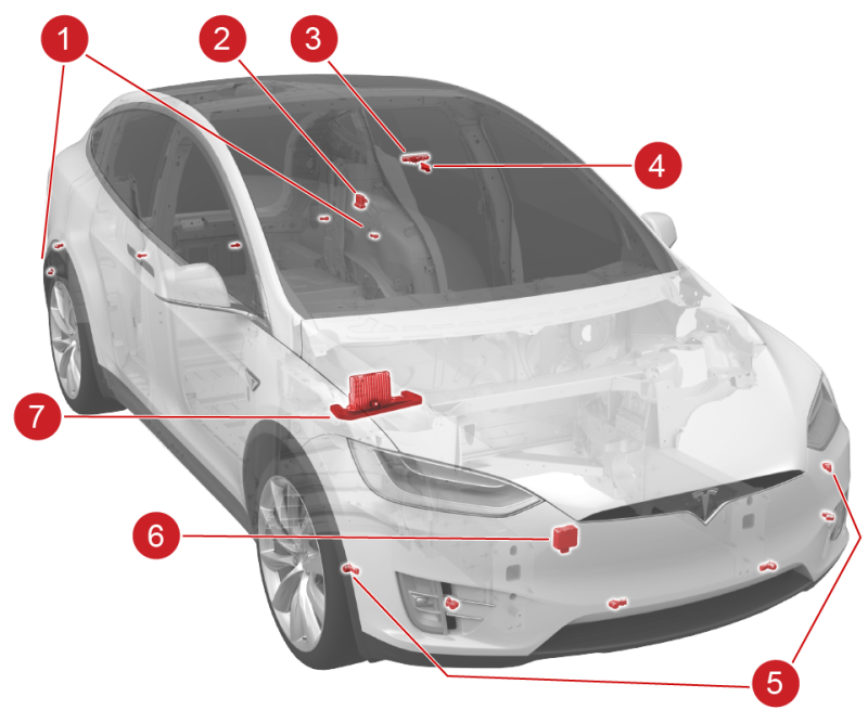
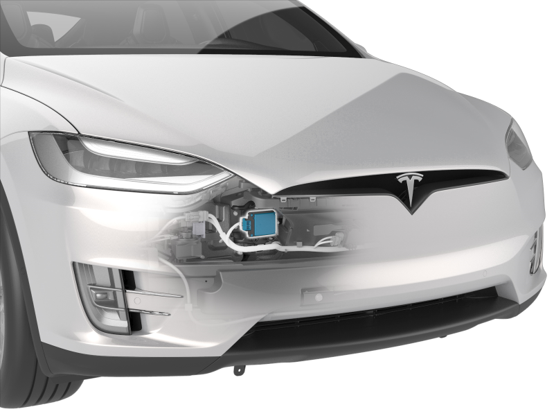
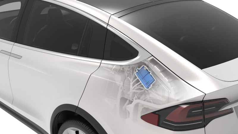
| 1. Rear ultrasonic sensors (x6) 2. Park Assist Electronic Control Unit (ECU) 3. Forward-facing camera 4. Rain / light sensor 5. Front ultrasonic sensors (x6) 6. Radar sensor 7. Driver Assistance ECU |
| Component Location Overview - Model X |
The above listed Driver Assist hardware interfaces with software running on the Driver Assistance electronic control unit (ECU), providing the driver with features like Traffic-Aware Cruise Control (TACC), Autosteer, Autopark, Forward Collision Warning, and Automatic Emergency Braking. Cameras and sensors give the vehicle a 360-degree view, which allows the vehicle to:
- Identify the road layout by detecting lane markings, curbs, barriers, and other obstacles.
- Identify a suitable travel path and speed.
Component Specificationslink
Driver Assistance ECUlink
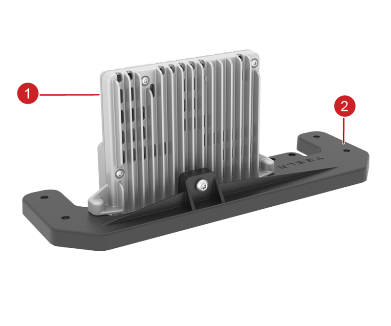
The Driver Assistance ECU is located behind the glove box. The Driver Assistance ECU connects to the forward-facing camera via coaxial cable for power and image data combined.
Communication with other ECUs happen over the Chassis CAN bus, where CAN messages provide the status of important modules, such as the Electronic Parking Brake (EPB), Park Assist, or electromechanical brake booster. The radar sends signals via a dedicated CAN bus about detected objects. Information about the road and objects ahead is also received from the camera vision processing. The algorithm inside the DAS ECU uses the available data to provide DAS features, by controlling other vehicle sub-systems (like drive unit, brakes, and steering) through CAN messages. The ECU directly controls the heater grid responsible for clearing the camera field of view of condensation, ice, or snow.
 |
|---|
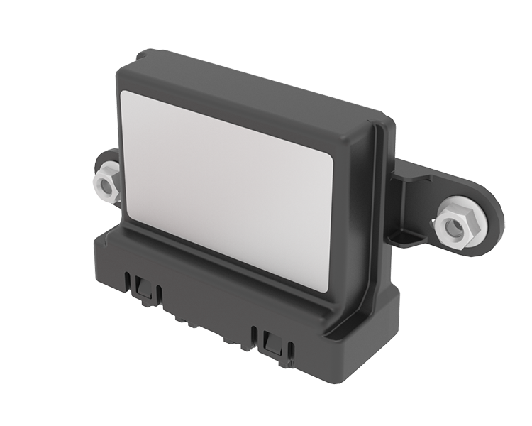
| 1. DAS ECU 2. ECU bracket |
| Driver Assistance ECU (Top View) |
 |
|---|
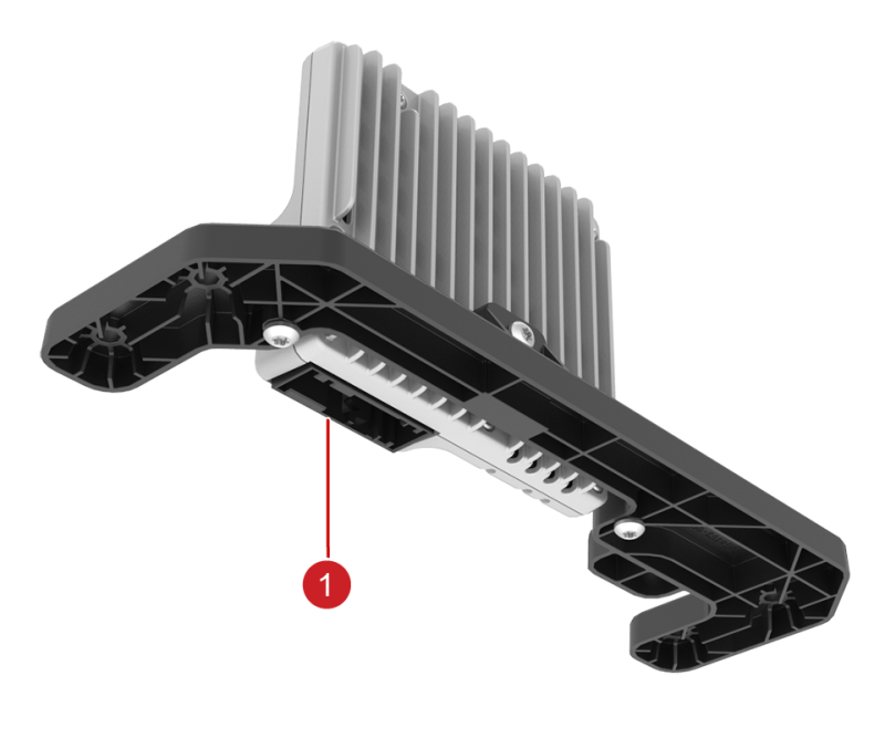
| 1. Main ECU connector |
| Driver Assistance ECU (Bottom View) |
Firmware Updatelink
The Driver Assistance ECU will receive its firmware update over the Chassis CAN. It will show on a firmware update log as DAS.
Diagnostics, Serviceability, and Calibrationlink
Alerts appear when any of the conditions below are sensed by the Driver Assistance ECU:
- Internal ECU issue (voltage, memory, initialization failure) detected.
- Issue communicating with the camera.
- Poor or no camera visibility.
- Camera calibration has changed or is out of bounds.
- CAN messages from other ECUs are not received or have invalid data.
- Issue with the camera heater grid.
- Issue with radar calibration or radar CAN communication.
Other alerts are set when Driver Assistance features are activated, canceled, or unavailable but do not relate to the Driver Assistance ECU itself. Inspect the components listed below before replacing the Driver Assistance ECU assembly:
- Ground and power wiring and connectors to the Driver Assistance ECU.
-
CAN wiring and connectors to the Driver Assistance ECU.
-
Coaxial wiring to the forward-facing camera.
The Driver Assistance ECU can be replaced separately from the forward-facing camera assembly. Calibration is required after replacement. Refer to the Service Manual for instructions on how to perform calibration using the camera calibration target and Toolbox.
- GNSS receiver
-
Inertial measurement unit (IMU)
-
Camera inputs
| Common Abbreviation | Definition |
|---|---|
| ESP | Electronic Stability Program Electronic Control Unit (ECU) |
| RCM | Restraints Control Module |
Cameraslink
Forward-facing Cameralink
 |
|---|
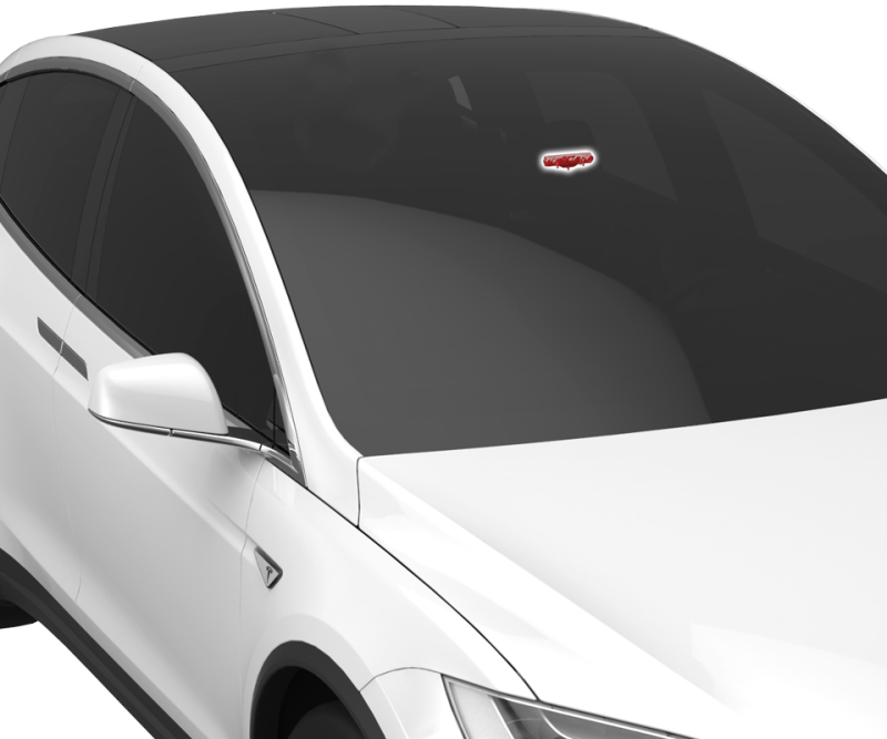
| Forward-Facing Camera Location |
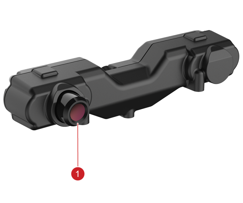 |
|---|
| 1. Camera |
| Forward-Facing Camera |
The forward-facing camera (also known as Monocamera) is one lens mounted on the windshield. It communicates via a coaxial cable with the Driver Assistance ECU located behind the glove box.
Specificationslink
- Horizontal field of view: 46 degrees
- Vertical field of view: 34 degrees
- Objects and vehicles detection range (conditions permitting): 80 m (87 yd)
Diagnostics, Serviceability, and Calibrationlink
If the camera is not working as expected, make sure that the connector on the back of the assembly is properly seated and nothing is blocking the view of the camera. Alerts will be triggered when the Driver Assistance ECU detects an internal issue, a calibration issue or the camera view is obstructed.
Potential points of failure:
- Internal failure of the Driver Assistance ECU or camera
- Camera view obstruction
- Wiring and connectors
The camera is individually replaceable. Calibration is required whenever the forward-facing camera or any component that contacts it is physically adjusted or removed from the vehicle.
Rear-View Cameralink
The rear-view camera has a wide-angle lens, which enables the driver to view a large area behind the vehicle. The camera signal is received by the Media Control Unit (MCU) to be processed further and shown on the UI. It is not used for any Driver Assist features.
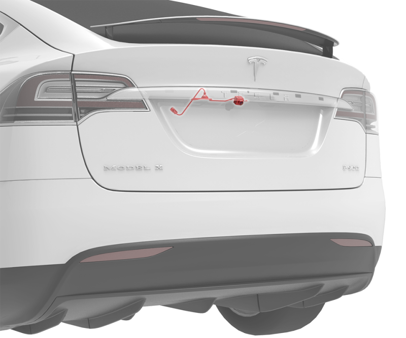 |
|---|
| Rear-View Camera Location |
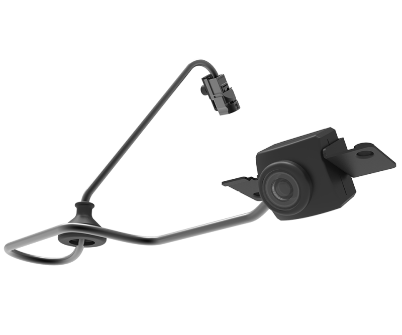 |
|---|
| Rear-View Camera with Connector |
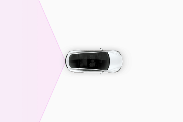 |
|---|
| Rear-View Camera Field of View |
Diagnostics, Serviceability, and Calibrationlink
If the rear-view camera is not operating as expected, inspect the connectors and wiring from the camera to the MCU. Confirm there are no issues with the touchscreen displaying the camera image.
Potential points of failure:
- Wiring and connectors
-
Camera
-
Media Control Unit (MCU)
The rear-view camera assembly is individually replaceable. The camera does not require calibration.
 |
|---|
| Radar Mounting Location (Radar for DAS HW2.5 and HW3 Shown) |
 |
|---|
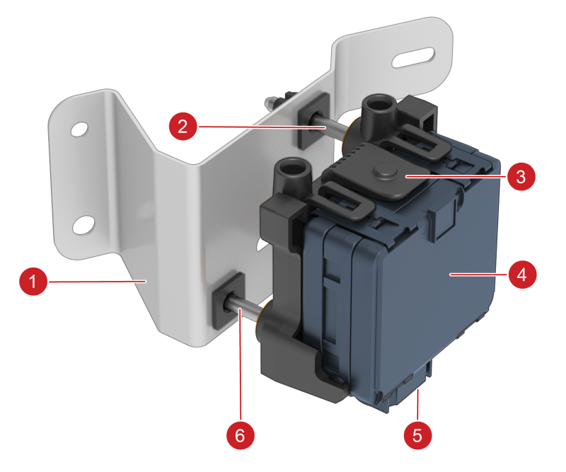
| 1. Radar bracket 2. Vertical alignment screw 3. Radar sensor bracket 4. Radar sensor assembly 5. Harness connector 6. Horizontal alignment screw |
| Radar Assembly |
- ± 45 degrees @ 10 m (33 ft)
- ± 10 degrees @ 60 m (197 ft)
- ± 9 degrees @ 100 m (328 ft)
- ± 7 degrees @ 140 m (459 ft)
-
± 6 degrees @ 160 m (525 ft)
-
Supply voltage range: 6.5V - 18V
- Nominal voltage: 14V
- Maximum detection range (conditions permitting): 160 m (525 ft)
- Operating temperature range: -40 to 85°C (-40°F to 185°F)
±3 degree
A radar calibration in service is required whenever the radar sensor, or any component that contacts it, is physically adjusted or removed from the vehicle.
Ultrasonic Sensorslink
 |
|---|
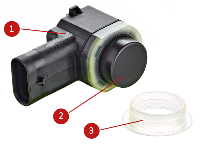
| 1. Sensor housing with connector 2. Sensor membrane 3. Decoupling ring |
| Park Assist Sensor |
Overview and Operating Principlelink
Ultrasonic sensors use the piezoelectric effect to measure distance to objects. The piezoelectric effect creates electricity in certain materials (crystals and ceramics) by applying mechanical stress and vice versa. The ultrasonic sensor has a membrane attached to this material and applying voltage will result in ultrasonic waves being sent out. Objects in the path of those waves will reflect them and create an echo received by the sensor and it is converted back to an electric signal.
To determine the distance to an object, a time-of-flight measurement is used based on the speed of sound. The sensor sends and receives sound waves from the same surface so there is a period of sending ultrasonic pulse and a listening period. The longer the listening period, the greater the detection range of the sensor, but the lower the pulse rate of the sensor. As the membrane vibrates to send out signal pulses, the membrane needs a short period to stop vibrating before it can be used to listen for the incoming signal. This time delay is called "ring down time" and it limits detection of very close objects (<10-20 cm / 4-8 in) as the return signal to the membrane may arrive at the sensor when it is still vibrating. This ring down time is regularly monitored so that the sensor can adapt its membrane drive frequency to the most efficient value.
In this Park Assist system, not all of the sensors transmit at once. During any given detection sequence, non-transmitting sensors are listening for echoes coming back from objects. These echoes are a result of the sound pulse sent by neighboring sensors that are actively transmitting during this time. The Park Assist Electronic Control Unit (ECU) uses the direct and indirect echoes to create a map of objects using the known sensor positions around the vehicle. This map is continuously updated based on the signals returning after each detection sequence. The transmit sequence and sensor settings can vary based on vehicle speed, ambient temperature, and vehicle status. For this to work properly all ultrasonic sensors have to be decoupled from the fascia by decoupling rings. They also prevent debris from getting into the sensor shell.
The ultrasonic system is composed of 12 ultrasonic sensors: 6 installed in the front bumper fascia and 6 installed in the rear bumper fascia. Each sensor is connected via a local interconnect network (LIN) interface to the Park Assist ECU. All sensors are held in place by a retainer on the inside of the fascia for a flush fit.
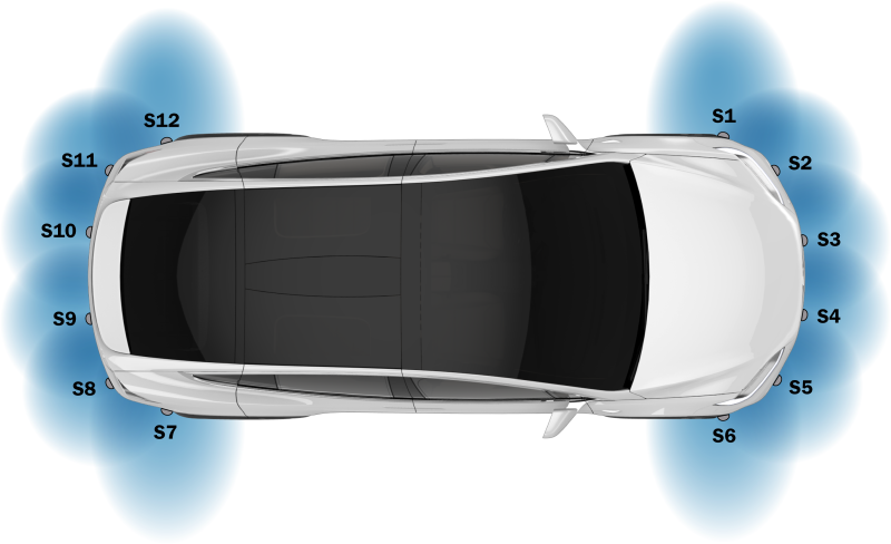
Numbering of the Ultrasonic Sensorslink
The sensors have a specific numbering sequence, starting with sensor 1 at the front left-hand side of the vehicle, and continuing in a clockwise sequence such that 7 is the rear right-hand side of the vehicle.
 |
|---|
| Ultrasonic Sensor Numbering |
Specifications and Limitationslink
Ultrasonic sensor specifications in ideal/nominal conditions (temperature 23°C (73°F), relative humidity 50%):
- Maximum detection range of the sensor is 5 m (16ft) and can be impacted by geometry and material of the detected object.
- Minimum detection range with accurate distance information is approximately 20 - 25cm (8 - 10in).
- Minimum detection range is approximately 10-15 cm (4 - 6in), presence of an object will be detected but distance information is inaccurate.
The side-facing ultrasonic sensors (S1 / S6 / S7 / S12) have a narrower field of view but more range to improve the detection of curbs and parking spots.
All ultrasonic sensors are unaffected by lighting conditions but are susceptible to "noise", such as wind turbulence, rain, snow, road spray, etc. Debris like snow, ice, or mud covering the sensors will prevent proper functionality.
Temperature and humidity have a large effect on the performance of the sensors. The following things will affect the performance of the ultrasonic sensor:
- Covering the sensors (wrap / vinyl).
- Painting the sensor membrane.
- Installing the incorrect decoupling ring.
Diagnostics, Serviceability, and Calibrationlink
The ultrasonic sensors are part of the Park Assist System. The Park Assist ECU and Driver Assistance ECU will trigger alerts when:
- A sensor is obstructed or has otherwise reduced performance.
- A short in the power supply to the sensor is detected.
- A communication issue is detected between the ECU and sensor.
- A communication issue is detected between the ECU and sensor when there is a compatibility mismatch (Tesla USS v/s USS from other manufacturers).
Toolbox has several tests to check the functionality of the ultrasonic sensors.
Ultrasonic sensors can be replaced individually and with no calibration required. Be aware that there are different generations and types of ultrasonic sensor available. To avoid incorrect installation, keyways on the connectors of the side-facing sensors and sensor retainers are different from the other locations. Make sure that after installation the sensor sits flush with the fascia and the decoupling ring is properly isolating the sensor.
Sensors come painted to match the vehicle color from the manufacturer. Refer to the applicable body shop documentation when repainting sensors as paint thickness can impact sensor performance.
Park Assist ECUlink
 |
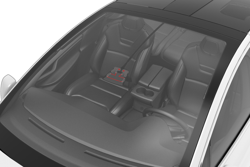
|---|
| Park Assist ECU Location |
 |
|---|
| Park Assist ECU |
The Park Assist ECU provides power to the ultrasonic sensors but also controls their behavior and runs diagnostics. It processes distance data and sends this information out via CAN messages. This data is utilized by the Driver Assistance ECU to provide features like Autopark, Lane Assist, Auto Lane Change, and others.
Firmware Updatelink
The Park Assist ECU receives its firmware update over the Chassis CAN. It will show on a firmware update log as PARK, Park Assist bootloader update (PARKBU), and Park Assist bootloader (PARKBL).
Diagnostics, Serviceability, and Calibrationlink
The Park Assist ECU can only be replaced as a whole. After replacement, a firmware update is required to match the version of the ECU with the rest of the vehicle. No calibration is required. Alerts will be set by the Park Assist ECU when:
- Issues with the ultrasonic sensors are detected.
- CAN messages from other ECUs are not received or have invalid data.
- An internal ECU issue is detected.
Potential points of failure:
- Power & ground to the Park Assist ECU
- CAN wiring
- Wiring to the ultrasonic sensors
Camera Heater Gridlink
 |
|---|
| Camera Heater Grid Location |
The camera heater grid is controlled by the Driver Assistance ECU and is used to clear the front-facing camera view of condensation, snow, or ice.
The heater grid will be activated when defrost is requested or when Autopilot anticipates ice or condensation based on occlusions and environmental conditions. The heater grid will never operate above +30°C or +86°F ambient temperature.
- Windshield temperature is above the activation temperature (+6°C or +44.6°F).
- Windshield defrost and preconditioning are off.
Diagnostics, Serviceability, and Calibrationlink
If the heater grid is not working as expected, make sure to inspect the wiring to it. Confirm the above enable conditions are met and that the ambient and windshield temperature sensors (if present) are reporting correct values.
An alert will be set by the Driver Assistance ECU when a short or open circuit is detected in the camera heater grid. Potential points of failure:
- Wiring and connectors
- Ambient temperature sensor
- Temperature sensor near windshield
- Driver Assistance ECU
The camera heater grid is part of the windshield and can only be replaced as a whole. After replacing the windshield, camera pitch angle verification is required. The camera heater grid is part of the windshield and can only be replaced as a whole. After replacing the windshield, camera pitch angle verification is required.
Driver Assist Featureslink
Note
Not all Driver Assist features are available in every country. See the local Owner's Manual on Feature Availability and if there are different conditions for activation.
Traffic Aware Cruise Control (TACC)link
| Sensors and Data Used | Forward facing cameras:
|
| Speed limitations | Minimum speed for activation:
|
If the vehicle is equipped with Autopilot convenience features, Traffic Aware Cruise Control (TACC) replaces the regular cruise control.
TACC maintains a driving set speed in the same way as standard cruise control but can also adjust the speed of the vehicle based on the distance to other vehicles in the same or adjacent lane (Undertake Assist). TACC will adjust the speed based on map data and during manual lane changes, reduce speed to target lane vehicles. TACC can be activated once traveling faster than 5 mph or 8 km/h, unless certain conditions allow an activation at even lower speeds. At standstill, TACC will activate if a vehicle is at least 5 feet (150 cm) detected ahead.
TACC is enabled by pulling the cruise control lever once or by pushing it up or down to the first or second position. If TACC was not enabled before, pushing the lever up or down sets the current speed as the cruise speed. Pulling the stalk sets the vehicle's current speed when no speed limit has been detected. When a speed limit is detected and shown in the cruise control symbol, this speed (+ possible speed warning offset) will be set as cruise control set speed when pulling the stalk, if the vehicle is going slower than the recognized speed limit the speed will be increased until it has reached the set speed.
If cruise is active, speed can be increased by pushing the lever up to the first position 1 km/h (1 mph) and 5 km/h (5 mph) with the second position. Pushing the lever down will decrease speed with the same steps. Holding the cruise lever pulled will set the cruise speed to the speed limit determined by Speed Assist including a potential set speed offset. Cruise can be canceled by the driver by pressing the brake, pushing the lever forward or shifting into a different gear.
Cruise will not be available when:
- The speed drops below 5 mph / 8 km/h and no lead vehicle detected.
- Driving speed exceeds 90 mph or 150 km/h.
- The driver's seat belt is unbuckled.
- The door is opened.
- The trunk or frunk is opened.
The driver can choose 7 different following distances via the cruise control lever.
The distance will increase when the wiper activity suggests poor road conditions or ambient temperature is low (< 3°C / 38°F).
Diagnostic Informationlink
If Traffic Aware Cruise Control does not become available, check:
- If a cruise control stalk signal change is logged.
If Traffic-Aware cruise control does not work as expected or aborts, check:
- If vehicle has been driven under mentioned limitations.
- For cruise control related alerts.
Curve Speed Adaptationlink
Curve Speed Adaptation (CSA) is a feature of TACC. CSA reduces the vehicle's speed in anticipation of upcoming curves or bends in the road. This is done by temporarily slowing the vehicle down to an appropriate speed.
CSA activates when:
- Taking a highway exit.
- Predicted lateral acceleration along the most probable path reaches a certain threshold (uses either local navigation data or online Tesla maps).
- Current measured lateral acceleration of the vehicle reaches a certain threshold.
Fleet Speedslink
Fleet Speeds helps to slow the vehicle down to an appropriate speed when entering and exiting highways or driving on interchanges with Autosteer or TACC active. Speed will be reduced to the average speed that other Tesla vehicles drove on that road section but will not exceed the speed limit set by the driver. The set speed on the UI will be reduced in increments of 5 mph or 10 km/h rounded up to match the average Fleet Speed, though speed will not drop below 25 mph or 40 km/h. As long as Fleet Speeds is active, an animation of the circle around the set speed value will be shown on the UI. Drivers can override the new speed with the accelerator or brake pedal (as for TACC in general) if they consider it inappropriate.
Entering highways (on-ramp):
- Fleet Speeds might slow the vehicle down (depending on current set speed).
- Speed can change dynamically similar to how the fleet reported speed changes.
- Once the vehicle is on the highway, it will accelerate back to the previous set speed.
Highway interchanges:
- Fleet Speeds might slow the vehicle down (depending on current set speed).
- Speed can change dynamically similar to how the fleet reported speed changes.
- Once the vehicle is in targeted space, it will accelerate back to the previous set speed.
Exiting highways (off-ramp):
- Fleet Speeds might slow the vehicle down (depending on current set speed).
-
Speed can change dynamically similar to how the fleet reported speed changes.
-
If the driver wants to change the set speed using the stalk, Fleet Speeds will stop updating the set speed but still limit the driving speed to speed of the fleet.
-
Upon leaving the exit, Fleet Speeds will be actively controlling the speed for at least 100 m (110 yd) up to 2 km (1.2 mi) until the next road speed limit is detected.
- Fleet Speeds becomes inactive after either the new detected speed limit is set, or the previous set speed is restored.
Diagnostic Informationlink
Fleet Speeds cannot be deactivated but depends on the availability on map data of the fleet's average speed. If Fleet Speeds does not work as expected or at all, check for incorrect localization to nearby roads resulting in incorrect speed adjustments.
Overtake Accelerationlink
When Traffic Aware Cruise Control is active, Overtake Acceleration helps passing a vehicle more quickly by briefly reducing the following distance to the target in front with the turn signal active. Overtake Acceleration will engage when:
- TACC is operating and detects a vehicle in front.
- No obstacles or vehicles are detected in the target lane.
-
Speed is above 72 km/h (45 mph) but below the TACC set speed.
-
Turn signal stalk is fully or partially engaged for the passing lane.
-
Accelerator pedal is not pressed.
Overtake Acceleration cancels when:
- Cruise set speed is reached.
- Changing lanes takes too long.
-
Vehicle gets too close to the vehicle ahead.
-
Turn signal stalk returns to neutral.
Diagnostic Informationlink
There are no feature specific signals available in logs.
Passing Lane Assist (Undertake Assist)link
Undertake Assist or Passing Lane Assist is designed to prevent passing vehicles with TACC active in a lane where it is not legally allowed. For example, this applies to continental Europe, where in right-hand traffic vehicles have to be passed in the left lane, passing on the right is not allowed. If moving faster in the slower lane than a vehicle ahead in the faster lane, Undertake Assist will match the speed and prevent passing. This behavior can be overridden by pressing the accelerator pedal, disabling TACC, or changing lanes. It stays disabled until the next disable/enable cycle of TACC.
Diagnostic Informationlink
There are no feature specific signals available in logs.
If Passing Lane Assist does not work as expected or at all, confirm the following:
- Vehicle speed is above 50 mph or 80 km/h.
- TACC or Autosteer is active.
- The faster vehicle is not too close as the camera might not be able to capture it.
Autosteerlink
| Sensors Used | Cameras:
|
| Speed Limitations | Minimum speed for Autosteer activation:
|
Autosteer is used to assist the driver in steering the vehicle on main roads and highways. Autosteer is an extension of TACC and keeps the vehicle in its lane while controlling cruise speed based on target vehicles ahead or map data. Always refer to the Owner's manual for the latest Autosteer visualizations, as the user interface is subject to change.
A gray steering wheel icon appears on the vehicle UI to indicate that Autosteer is available for use, but not actively steering the vehicle.
The Autosteer feature uses the front camera(s) to recognize lane markings to center the vehicle. Based on camera inputs, the Driver Assistance ECU will calculate an appropriate driving path for the vehicle.
Autosteer is designed to correct for external disturbances that may affect the vehicle’s steering, such as crosswinds or poor wheel alignment. If obstacles like guard rails are detected on one side, Autosteer will offset the vehicle within the lane to increase free space there.
Different from TACC only driving, Autosteer restricts the maximum speed depending on the road's speed limit (only off highway). The driver can go above the speed limit by overriding with the accelerator pedal or setting a relative speed limit warning on the UI. If the speed limit of the current road is unknown a speed limit appropriate to the detected road class will be used.
While driving with Autosteer active, the driver’s hands are required to be on the steering wheel. This will be checked at certain intervals by querying the driver applied torque on the steering wheel by the power steering system. The interval varies by region, weather conditions, road geometry and class, detected vehicles, constructions zones, and speed. If the driver does not respond to the audio and visual reminders on the UI, Autosteer will abort and gradually slow the vehicle down to a standstill. If the driver chooses to ignore the "Apply light force to steering wheel" reminders 3 times or accelerates over the Autosteer speed limit, Autosteer will be disabled until the next drive cycle. If Autosteer is active but is unable to continue due to lack of information, the driver is required to take over steering control and is warned by a series of chimes and a driver-facing alert, "Take over immediately." While driving with Autosteer active, the driver’s hands are required to be on the steering wheel. This will be checked at certain intervals by querying the driver applied torque on the steering wheel by the power steering system. The interval varies by region, weather conditions, road geometry and class, detected vehicles, constructions zones, and speed. If the driver does not respond to the audio and visual reminders on the UI, Autosteer will abort and gradually slow the vehicle down to a standstill. If the driver chooses to ignore the "Apply light force to steering wheel" reminders 3 times or accelerates over the Autosteer speed limit, Autosteer will be disabled until the next drive cycle. If Autosteer is active but is unable to continue due to lack of information, the driver is required to take over steering control and is warned by a series of chimes and a driver-facing alert, "Take over immediately."
To cancel Autosteer the driver pushes the cruise control stalk forward, moves the steering wheel, presses the brake pedal or shifts out of Drive. Normally, 2 to 4 Nm of torque on the steering wheel is required to cancel Autosteer, depends on the vehicle model and region of operation. When the turn signals are on, the amount of force to cancel Autosteer is ~1 Nm (depends on vehicle platform). When Autosteer is canceled, a chime will sound, UI displays the lane markings in white and the Autosteer icon changes from blue to gray.
Diagnostic Informationlink
If Autosteer will not activate, check:
-
If all Autosteer activation criteria is met (especially UI Autosteer setting is on, trailer mode is off, and lane markings are detected).
- If a cruise stalk double pull is registered.
-
If there are any alerts relating to the Driver Assistance ECU, cameras.
- If there are any Autosteer unavailable alerts.
If Autosteer does not perform as expected or aborts, check:
- If the vehicle is driven in conditions mentioned under limitations.
- If camera calibration is fully complete and the camera pitch is in specification.
- If there are any alerts on Autopilot steering angle or steering angle rate saturation indicating a potential issue in identifying lane markings.
- If there are any alerts on Autopilot aborting giving the reason why Autosteer could not continue steering the vehicle.
See also Traffic Aware Cruise Control, as some limitations can affect Autosteer behavior.
Auto Lane Changelink
Automatic Lane Change (ALC) is used to assist in changing lanes with Autosteer active. The minimum speed at which ALC is available depends on the region, adjacent lane speeds and road class.
- The driver's hands must be detected on the steering wheel before being able to activate Auto Lane Change.
-
Activation is only possible on major highways and well-marked local roads with multiple lanes.
-
Lane changes will abort if not completed within 5 seconds after using the turn indicator.
The adjacent lane is checked for rear, side, and front objects, and a trajectory for the lane change is calculated. Once there are no objects that interfere with the Automatic Lane Change maneuver and a non-solid lane marking is detected, the vehicle is brought closer to the vehicle in front of it with Overtake Acceleration and starts to depart the lane. Midway through the lane change, the camera detects the lane marking of the outside lane and the UI is updated to show the outside lane.
The driver can also abort the lane change by pressing the brake pedal, moving the steering wheel (1 Nm torque required) or move the turn indicator stalk to the opposite direction.
Automatic Lane Change performs one lane change at a time. Moving into a second lane requires activating the turn signal a second time after the first lane change is complete. Auto Lane Change is designed for use on main roads and highways only where lane markings are visible and clear, and the driving conditions are more predictable.
Diagnostic Informationlink
The only driver-facing indication of Auto Lane Change availability is the UI displaying outer lane markings of adjacent lanes.
If Auto Lane Change does not start, check:
- If all Automatic Lane Change activation criteria is met (especially the lane marking detection).
- If there are any alerts relating to the Driver Assistance ECU, camera(s), and/or ultrasonic sensors when equipped .
- If there are any Lane Change unavailable alerts.
If Auto Lane Change does not perform as expected or aborts, check:
- If the vehicle is driven in conditions mentioned under limitations.
- If the driver aborted the lane change (steering, pedal or turn indicator input).
- If there are any alerts relating to the Driver Assistance ECU, cameras .
- If there are any Lane Change abort alerts.
Traffic Light and Stop Sign Controllink
Traffic Light and Stop Sign Control is designed to recognize and respond to traffic lights and stop signs, slowing vehicles to a stop when using Traffic-Aware cruise control or Autosteer. This feature uses the vehicle's forward-facing cameras, in addition to GNSS data, and slows the vehicle for all detected traffic lights, including green, blinking yellow, and off lights in addition to stop signs and some road markings. As vehicles approach an intersection, the touchscreen displays a notification indicating the intention to slow down. The driver must confirm that they want to continue, or the vehicle will stop at the red line displayed on the touchscreen's driving visualization.
Note
Traffic Light and Stop Sign Control is a BETA feature and works best on roads that are frequently driven by Tesla vehicles. Traffic Light and Stop Sign Control attempts to stop at all traffic lights, including green lights.
Diagnostic Informationlink
Limitations of Autosteer and Its Associated Functionslink
- Autosteer is unable to accurately determine lane markings. For example, lane markings are excessively worn, have visible previous markings, have been adjusted due to road construction, are changing quickly (lanes branching off, crossing over, or merging), objects or landscape features are casting strong shadows on the lane markings, or the road surface contains pavement seams or other high-contrast lines.
- Visibility is poor (heavy rain, snow, fog, etc.).
- A camera(s) or sensor(s) is obstructed, covered, or damaged.
- Driving on hills.
- Approaching a toll booth.
- Driving on a road that has sharp curves or is excessively rough.
-
Bright light (such as direct sunlight) is interfering with the view of the camera(s).
-
A vehicle is detected in the blind spot when the turn signal is engaged.
- Vehicle is being driven very close to a vehicle in front of it, which is blocking the view of the camera(s).
Autopark and Summonlink
| Feature | Specifications |
|---|---|
| Sensors Used | GNSS / navigation data:
|
| Speed Limitations | Maximum speed for parking slot detection:
|
Summonlink
Summon is a feature that can move the vehicle in and out of a parking space without a driver needing to be in it.
Once activated, Summon will travel as commanded forward or reverse for up to 12 m (40 ft) trying to avoid obstacles if possible, with a maximum speed of 1.6 km/h (1 mph). Summon will finish once the stop criteria (front or rear distance) from the touchscreen are met or the user requests a stop on the mobile app or key fob. Summon aborts when any of the following occur:
- A door handle is pressed.
- The front trunk or trunk button on the key fob is pressed.
- Driver intervenes by using with steering wheel, brake, accelerator pedal, or gear selection.
- If the vehicle cannot move for more than 2 seconds due to an obstacle.
Summon can be configured to open and close HomeLink garage doors once it has learned the GNSS location where it should send a HomeLink command. If an obstacle in the path of travel is detected in this location, Summon will assume it is a closed garage door and use HomeLink to open it (be aware that there is only one command to open and close via HomeLink). If the path is clear, Summon will continue and also close the garage door once finished. Summon is not looking at lane markings and will not attempt to line up with those.
Diagnostic Informationlink
If Summon fails to activate, check:
- If Summon is enabled on the UI.
- If all activation criteria are met (differs per region).
- If both phone with the mobile app and vehicle have connectivity.
- If key fob commands are registered.
- Logs for Summon (APC) abort and activation alerts.
If Summon does not perform as expected, check:
- If the feature is used in conditions mentioned under limitations.
- Logs for Summon (APC) abort and activation alerts.
Limitationslink
- The driving path is sloped. Summon is designed to operate on flat roads only (up to 10% grade).
-
A raised concrete edge is detected. Summon will not move the vehicle over an edge that is higher than approximately 1 in (2.5 cm).
-
Weather conditions (heavy rain, snow, fog, or extremely hot or cold temperatures) are interfering with object detection.
-
Vehicle is in Trailer Mode or an accessory is attached.
Lane Assistlink
| Sensors used | Forward-facing camera
|
| Speed limitations | Side Collision Warning
|
Side Collision Warninglink
Side Collision Warning (SCW) is designed as an advanced blind spot warning system that is able to detect vehicles at all four corners of the vehicle. Radiating lines around the vehicle avatar are shown on the UI when objects are detected by the ultrasonic sensors (when equipped and configured). As a vehicle gets closer, the radiating line color changes from white, to yellow, to red. When the driver activates the turn signal with a vehicle close in this direction, the UI will show the lane line next to it in red. If a collision is considered likely, a configurable chime will sound.
Diagnostics, Serviceability, and Calibrationlink
When Side Collision Warning is not working at all, or not working as expected, check:
- If limitations mentioned below apply.
- For any ultrasonic sensor (when equipped and configured) related alerts in logs.
- For SCW noisy environment alerts in logs.
- For SCW unavailable alerts in logs.
Side Collision Assistlink
Side Collision Assist (SCA) is based on Side Collision Warning and becomes active if a side collision is imminent. A warning sound is played, and the DAS ECU commands the steering to pull the vehicle away from a potential impact. SCA does not become active when Autosteer is active.
SCA will only activate on highways below a certain steering angle and if the last intervention was more than 10 minutes ago.
If Side Collision Assist is actively steering the vehicle away from an object, it will cancel if:
- Steering wheel torque above 4 Nm is applied in the opposite direction.
- It has been active for more than 1 second.
- Above mentioned speed limits are reached.
- steering and steering rate reached a certain limit.
- The vehicle is about to leave the lane.
Diagnostics, Serviceability, and Calibrationlink
An alert is logged when a Side Collision Avoidance has occurred containing additional data related to the event.
Lane Departure Warninglink
Lane Departure Warning (LDW) uses the camera to monitor the lane markings on the road directly in front of the vehicle. If either of the front wheels cross over a lane marking and the respective turn signal is off, there is a slight vibration in the steering wheel and a visual warning on the UI is also displayed. A threshold called the Time to Lane Crossing (TLC) determines whether a lane departure warning will be triggered. The DAS ECU monitors the distance between the outside of the front wheels and the inner wall of the nearest lane boundary, as well as the vehicle’s lateral velocity in order to calculate the TLC value.
In cases where the vehicle is directly adjacent to the lane boundary due to a driver's style of driving or other reasons, the Lane Departure Warning feature is designed to avoid repeated alerts. The warning will trigger on the first instance of approaching the lane line or the lane boundary. The drive will not receive a second warning unless the vehicle's wheels leave and re-enter the reset warning threshold boundary.
Diagnostics, Serviceability, and Calibrationlink
LDW can separately be turned on or off. To test the steering wheel actuator and reproduce a condition, the vehicle needs to be driven.
Note
Be aware of the haptic feedback variation between first and later generation DAS vehicles due to different steering racks with different actuators that create the vibration.
Escalated Lane Departure Warninglink
Escalated Lane Departure Warning (ELDW) alerts the driver if Autosteer is inadvertently canceled or failed to activate. The chime and visual warning will only appear if the driver's hands are not detected on the steering wheel and the vehicle is about to leave the lane or road. It will also be triggered if no hands on the steering wheel are detected within 40 seconds after Autosteer cancellation. This feature is not linked to Lane Departure Warning and cannot be turned off.
Note
Depending on the region, ELDW will be suppressed when indicators are active (North America for example).
Diagnostics, Serviceability, and Calibrationlink
An alert in logs will be set when Escalated Lane Departure Warning becomes active. The alert data will provide more information why alert was triggered. When ELDW never triggers, check:
- If above mentioned conditions are met.
- If the hands-on steering wheel detection works.
When ELDW triggers unexpectedly, check:
- If the turn signal was active when crossing lane markings (where applicable)
- If the hands-on steering wheel detection works.
Limitationslink
- Visibility is poor and lane markings are not clearly visible (due to heavy rain, snow, fog, etc.).
- Bright light (such as from oncoming headlights or direct sunlight) is interfering with the view of the camera(s).
- A vehicle in front of the vehicle is blocking the view of the camera(s).
- The windshield is obstructing the view of the camera(s) (fogged over, dirty, covered by a sticker, etc.).
- Lane markings are excessively worn, have visible previous markings, have been adjusted due to road construction, or are changing quickly (for example, lanes branching off, crossing over, or merging).
- The road is narrow or winding.
-
Objects or landscape features are casting strong shadows on lane markers.
-
Weather conditions (heavy rain, snow, fog, or extremely hot or cold temperatures) are interfering with sensor operation.
-
An object that is mounted to the vehicle is interfering with and/or obstructing a sensor (such as a bike rack or a bumper sticker).
- The vehicle is being driven on sharp corners or on a curve at a relatively high speed.
- The vehicle is drifting into another lane, but an object (such as a vehicle) is not present.
- A vehicle in another lane cuts in front of the vehicle or drifts into the driving lane.
Collision Avoidance Assistlink
| Feature | Specifications |
|---|---|
| Sensors Used | Forward-Facing Camera(s):
|
| Speed Limitations | Minimum speed for Forward Collision Warning & Automatic Emergency Braking activation:
|
Collision Avoidance Assist consists of the following features:
- Forward Collision Warning provides a visual and audible warning if there is a high risk of a frontal collision.
- Automatic Emergency Braking provides braking to reduce the impact of a frontal collision.
- Object-Aware Acceleration will reduce motor torque to reduce the impact of a collision when the accelerator was accidentally pressed.
Forward Collision Warninglink
The cameras monitor the area in the driving path for the presence of vehicles, pedestrians, and/or other objects. If a collision is deemed unavoidable given the current trajectory, and unless the driver takes corrective action, a warning chime will be triggered and the object in front will be highlighted in red on the UI. The warnings stop immediately if the risk of collision is reduced. For example, if the driver decelerates or stops the vehicle, or if the vehicle in front moves out of the driving path.
Forward-facing camera(s):
- Used to determine speed limit
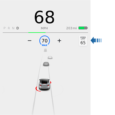 |
|---|
| Speed Limit Shown (Model 3 UI with US Speed Limit) |
The speed limit signs are processed by the vision chip and this information is sent to the DAS ECU. The recognized speed limit is compared against the stored navigation speed limit data to determine the speed limit of the road at the current location. In situations where the system is not certain about the accuracy of the most recently acquired speed limit (speed limit too high/low or does not match navigation data), the speed limit sign will not display on the instrument cluster and no warnings will be issued. Any time the vision system sees a new speed limit sign, it will try to associate this information with the latest navigation data in an attempt to associate that sign with a sign that belongs to a specific road class and display the information to the driver. - For any camera related alerts.
- Visibility is poor and speed limit signs are not clearly visible (due to heavy rain, snow, fog, etc.).
- Bright light (such as from oncoming headlights or direct sunlight) is interfering with the view of the camera(s).
- The vehicle is being driven very close to a vehicle in front of it which is blocking the view of the camera(s).
- The windshield is obstructing the view of the camera(s) (fogged over, dirty, covered by a sticker, etc.).
- Speed limit signs are concealed by objects.
- Traffic signs do not conform to standard recognizable formats.
Auto High Beamlink
Body Controller Module (BDY)Body Controller Module (BDY)
Autowiperslink
First generation Driver Assistance vehicles use a dedicated rain and light sensor (RLS) to detect rain drops on the windshield and perform automatic windshield wiping. There are two sensitivity levels (low and high) for Autowipers, which can be selected using the wiper stalk. The body controller will activate wipers based on rain intensity and selected wiper speed. Wipers will operate in a manual intermittent mode if the RLS is not available. Refer to Rain / Light / Solar / Humidity (RLSH) Sensor in the Thermal Management Theory of Operation for more information.
Diagnostic Informationlink
If Autowipers is not working at all or as expected, check:
-
If the fisheye camera view is obstructed or dirty.
-
Rain and light sensor and wiring.
Additional Informationlink
Driver Assistance Feature Matrixlink
| Feature | Feature type | Autopilot configuration | DAS hardware generation |
|---|---|---|---|
| Automatic Emergency Braking | Active, Safety | None, Basic, Highway, Enhanced, Full Self-Driving | HW1, HW2, HW2.5, HW3, HW4 |
| Forward Collision Warning | Passive, Safety | None, Basic, Highway, Enhanced, Full Self-Driving | HW1, HW2, HW2.5, HW3, HW4 |
| Object-Aware Acceleration | Active, Safety | None, Basic, Highway, Enhanced, Full Self-Driving | HW1, HW2, HW2.5, HW3, HW4 |
| Blind Spot Warning | Passive, Safety | None, Basic, Highway, Enhanced, Full Self-Driving | HW1, HW2, HW2.5, HW3, HW4 |
| Lane Departure Warning | Active, Safety | None, Basic, Highway, Enhanced, Full Self-Driving | HW1, HW2, HW2.5, HW3, HW4 |
| (Emergency) Lane Departure Avoidance | Active, Safety | None, Basic, Highway, Enhanced, Full Self-Driving | HW2, HW2.5, HW3, HW4 |
| Auto High Beam | Passive, Safety | None, Basic, Highway, Enhanced, Full Self-Driving | HW1, HW2, HW2.5, HW3, HW4 |
| Autowipers | Passive, Safety | None, Basic, Highway, Enhanced, Full Self-Driving | HW1, HW2, HW2.5, HW3, HW4 |
| Speed Assist | Passive, Safety | None, Basic, Highway, Enhanced, Full Self-Driving | HW1, HW2, HW2.5, HW3, HW4 |
| Traffic Aware Cruise Control | Active, Convenience | Basic, Highway, Enhanced, Full Self-Driving | HW1, HW2, HW2.5, HW3, HW4 |
| Autosteer | Active, Convenience | Basic, Highway, Enhanced, Full Self-Driving | HW1, HW2, HW2.5, HW3, HW4 |
| Auto Lane Change | Active, Convenience | Highway, Enhanced, Full Self-Driving | HW1, HW2, HW2.5, HW3, HW4 |
| Autopark | Active, Convenience | Highway, Enhanced, Full Self-Driving | HW1, HW2, HW2.5, HW3, HW4 |
| Navigate on Autopilot | Active, Convenience | Highway, Enhanced, Full Self-Driving | HW2, HW2.5, HW3, HW4 |
| Summon | Active, Convenience | Highway, Enhanced, Full Self-Driving | HW1, HW2, HW2.5, HW3, HW4 |
| Smart Summon | Active, Convenience | Enhanced, Full Self-Driving | HW2, HW2.5, HW3, HW4 |
| Traffic Light and Stop Sign Control | Active, Convenience | Full Self-Driving | HW3, HW4 |
| Stop Light and Stop Sign Warning | Passive, Convenience | Basic, Highway, Enhanced, Full Self-Driving | HW2, HW2.5, HW3, HW4 |
Note
- Passive features do not take over vehicle control, they provide an alert to the driver. Active features take over control of the vehicle.
- Safety features are standard on all Tesla vehicles equipped with Driver Assist hardware.
- Convenience features depend on which Autopilot configuration the customer has purchased.
Summary of Driver Assistance System Hardware Generationslink
| Driver Assistance System Hardware | Generation 1 (HW1) | Generation 2 (HW2) | Generation 2.5 (HW2.5) | Generation 3/3.1/3.2 (HW3/HW3.1/HW3.2) | Generation 4 (HW4) |
|---|---|---|---|---|---|
| Vehicles | Model S, X | Model S, X | Model S, X, 3 | Model S, X, 3, Y, Palladium S, Palladium X | Palladium S, Palladium X, Model Y, 2024+ Model 3, Cybertruck |
| Cameras |
|
|
|
|
|
| Driver Assistance ECU |
|
|
|
|
|
| GNSS | GNSS antenna connected to MCU | GNSS antenna connected to Driver Assistance ECU and data forwarded via Ethernet | GNSS antenna connected to Driver Assistance ECU and data forwarded via Ethernet | GNSS antenna connected to Driver Assistance ECU and data forwarded via Ethernet | GNSS antenna connected to Driver Assistance ECU and data forwarded via Ethernet |
| Gateway Driver Assist configuration | MonoCam | ParkerPascal | ParkerPascal2_5 or PARKER_PASCAL_2_5 | TeslaAP3 or TESLA_AP3 | TESLA_AP4 |