Thermal Managementlink
Last updated: October 10, 2024
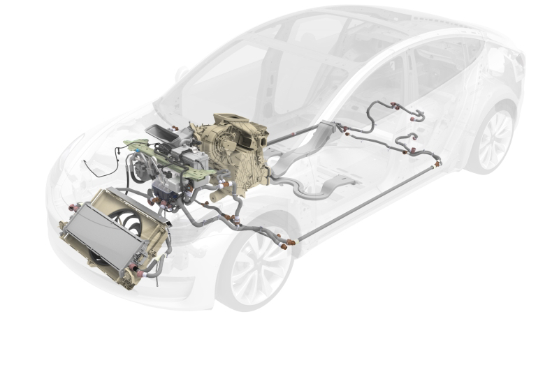
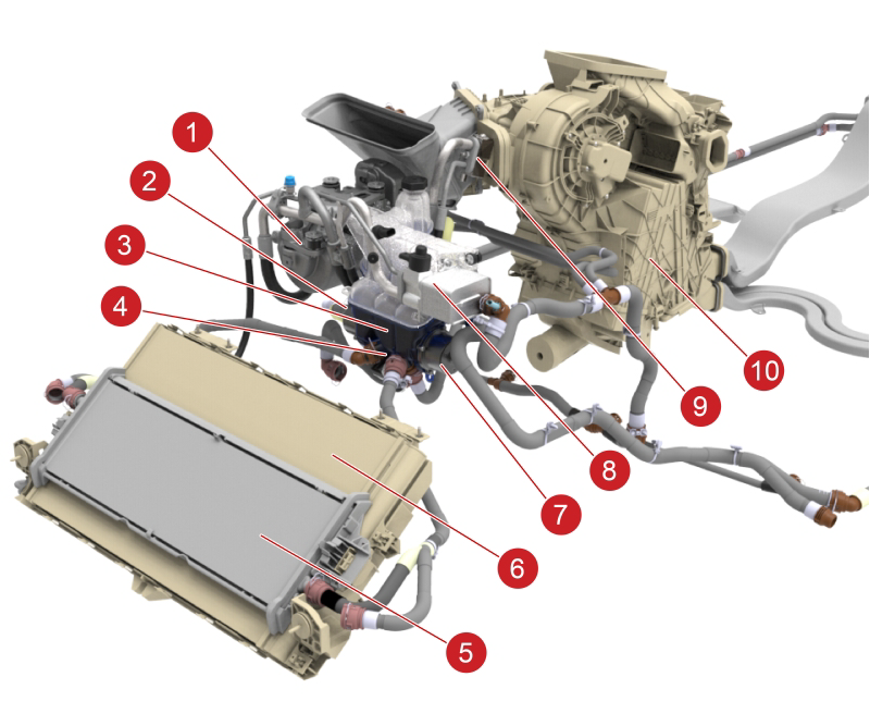
Component Location Overviewlink
 |
|---|
| Thermal Management System |
 |
|---|
| 1. A/C compressor 2. Powertrain coolant pump 3. Coolant reservoir (superbottle) 4. 5-Way valve 5. Radiator 6. Condenser 7. Battery coolant pump 8. Coolant chiller / Electronic expansion valve (EXV) assembly 9. Thermal expansion valve (TXV) 10. HVAC case |
| Thermal Management Components |
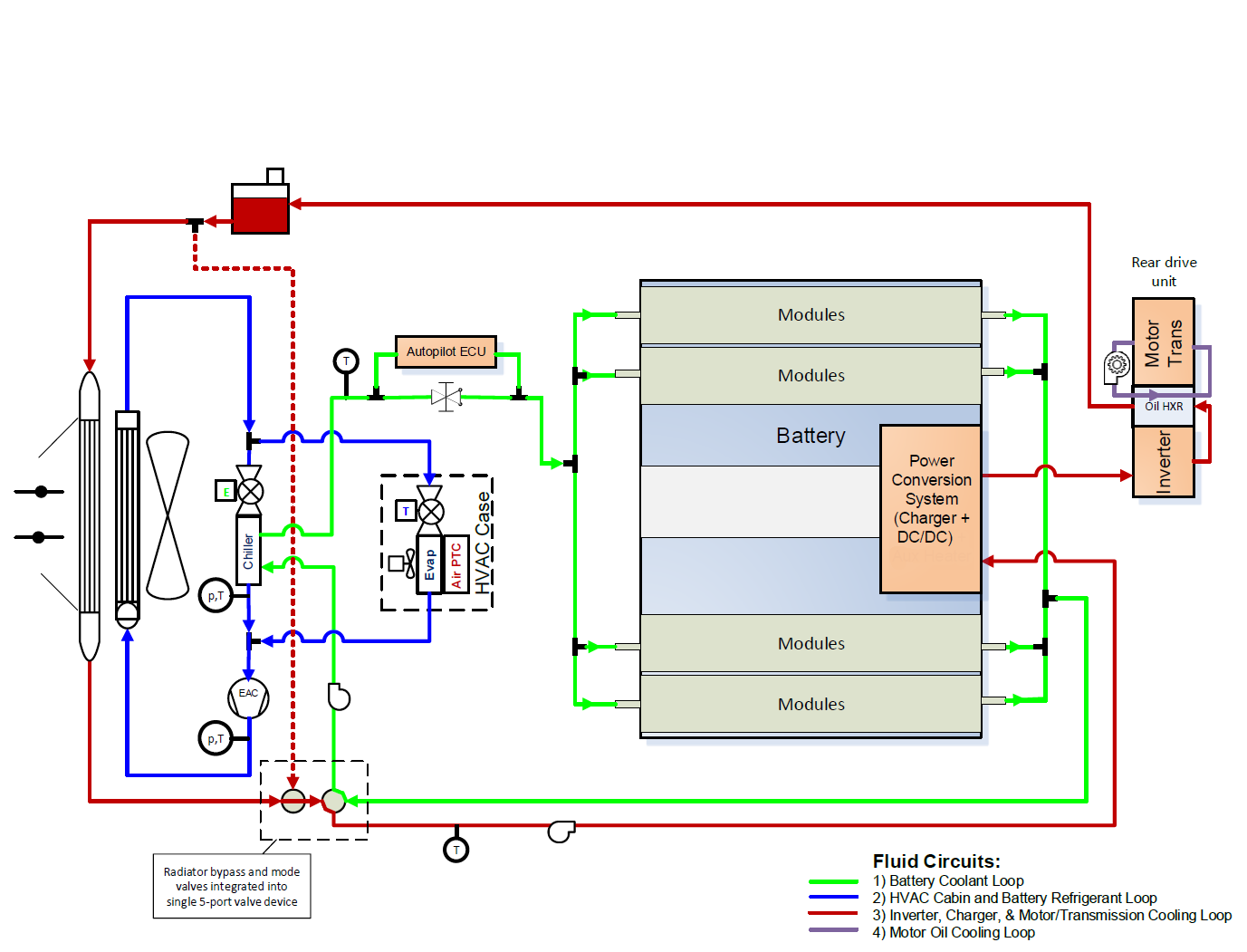
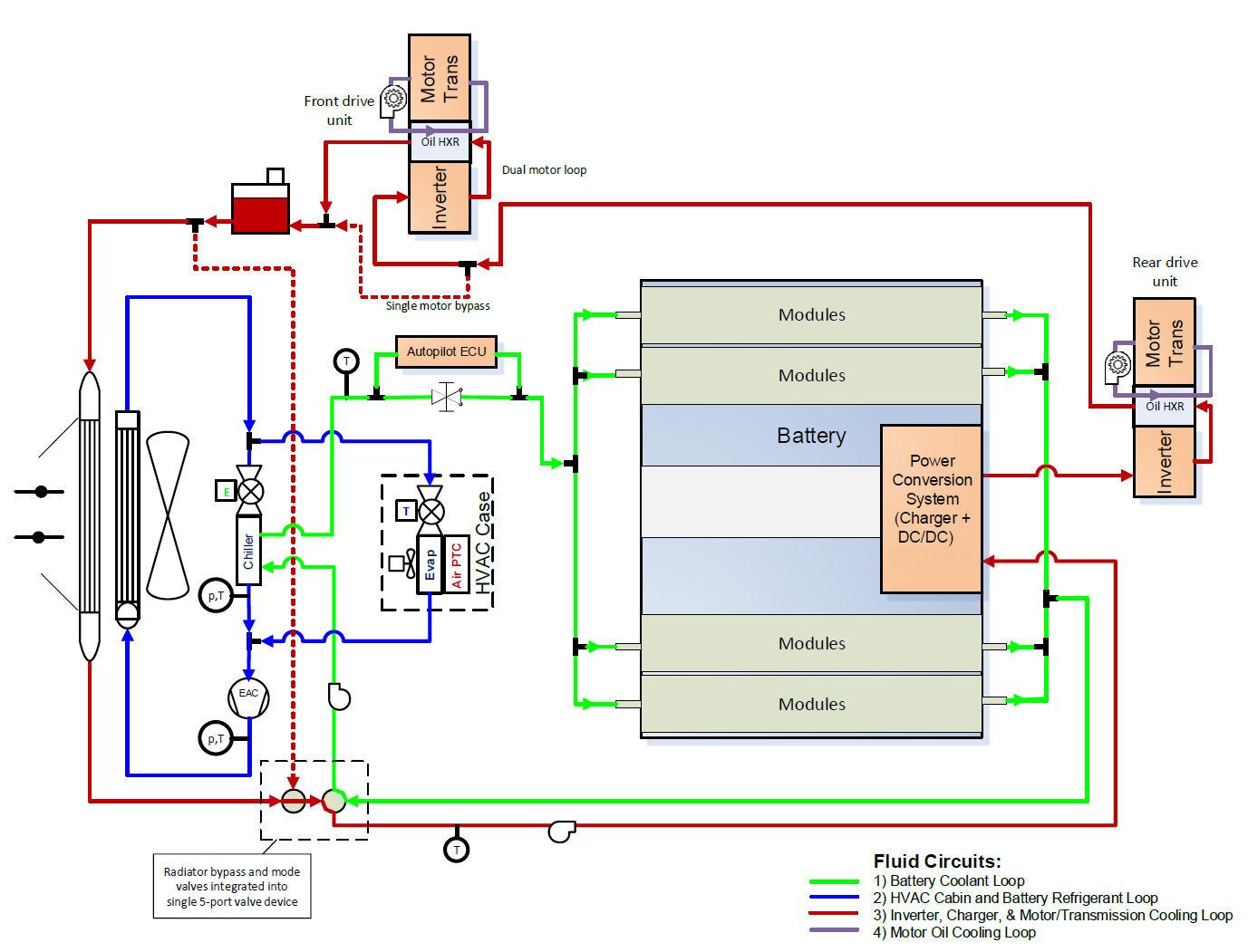
Thermal System Diagramlink
 |
|---|
| Rear Wheel Drive, System Diagram |
 |
|---|
| All Wheel Drive, System Diagram |
General System Operationlink
The cabin heating, ventilation, air-conditioning (HVAC) system and thermal management system control the:
- Cabin air flow volume, temperature, and humidity
- High Voltage (HV) battery temperature
- Powertrain (PT) and HV electronic systems temperatures
The cabin HVAC system and thermal management system are interconnected and share key components. For simplicity, these subsystems will be discussed separately.
Communication and Controllink
CAN / LIN communication
The following components communicate on the 500K Vehicle Controller Area Network (CAN) bus:
- Vehicle Controller (VC) Front
- Positive Temperature Coefficient (PTC) Air Heater
- HVAC Compressor
- Vehicle Controller (VC) Left
- Vehicle Controller (VC) Right
The Tesla HVAC Windshield sensor communicates on the Local Interconnect Network (LIN) bus.
Component Communication and Control
| Vehicle Controller (VC) LEFT | Vehicle Controller (VC) FRONT | Vehicle Controller (VC) RIGHT |
|---|---|---|
| HVAC Case Blower | Condenser Fan | HVAC Case Actuators / Sensors |
| Battery Pump | PTC Cabin Heater | |
| Powertrain Pump | ||
| Active Shutters | ||
| Low Coolant Sensor | ||
| 5-Way Coolant Valve | ||
| EXV Valve | ||
| TXV Solenoid | ||
| A/C Compressor | ||
| Ambient Temperature Sensor | ||
| Battery Coolant Inlet Temperature Sensor | ||
| Powertrain Coolant Inlet Temperature Sensor | ||
| Refrigerant Suction Temperature / Pressure Sensor | ||
| Refrigerant Discharge Temperature / Pressure Sensor |
Vehicle Thermal Systemlink
Battery and Powertrain Heating and Coolinglink
HV Battery and Powertrain Heating / Cooling
The vehicle thermal system components include a radiator, coolant hoses, coolant pumps, and a 5-Way valve. The vehicle thermal system heats or cools the coolant that circulates through the HV Battery and powertrain loop components. The HV Battery loop consists of the HV Battery, chiller, and autopilot module. The powertrain loop consists of the Power Conversion System (PCS), drive unit(s), radiator, and coolant reservoir (superbottle).
HV Battery and Powertrain Heating and Cooling Modes
Using the 5-Way valve, the vehicle thermal system can switch between modes of coolant routing. The system automatically implements the most appropriate mode according to the prevailing conditions.
The following modes are available for heating and cooling:
-
Series mode configures the cooling system so that the HV battery and powertrain are heated or cooled in series, with heat transfer occurring between the two subsystems. Series mode is used in the following circumstances:
-
HV Battery heating during cold soak conditions
During cold soak conditions, coolant flows through the drive unit and it absorbs heat. The warmed coolant bypasses the radiator and flows into the HV Battery to warm the HV Battery cells. If additional heating is required, the system switches the drive unit(s) into Waste Heat Mode, which uses additional energy to create heat in the drive unit and transfer this waste heat to the coolant.
-
HV Battery and powertrain cooling in low ambient temperatures
During low ambient temperatures, the HV Battery and Powertrain are cooled using only the radiator, without active cooling. In low ambient temperatures, the A/C compressor and chiller system are not used for HV Battery cooling.
-
Powertrain cooling during high ambient temperature
In extremely hot conditions and when the radiator cooling of the powertrain is limited, the HV Battery can act as a thermal capacitor to absorb powertrain heat, which allows the drive unit(s) to run cooler. This operation improves motor efficiency, but is only effective until the HV Battery temperature reaches its thermal limits. To extend high temperature operation, active cooling uses the chiller and A/C compressor to cool the coolant going to the HV Battery and other powertrain components.
-
-
Parallel mode configures the cooling system so that the HV Battery and powertrain loops run decoupled from each other and do not appreciably transfer heat between the two systems.
Parallel mode allows the most efficient use of the radiator for powertrain cooling, because the powertrain coolant can be much hotter than HV Battery coolant. Parallel mode also allows the HV Battery to heat itself gradually, without the need for active cooling, even when the HV Battery absorbs significant amounts of powertrain waste heat.
If the HV Battery requires cooling but the powertrain does not, the battery coolant chiller can be activated solely to cool the HV Battery. During charging, the charger is cooled on the powertrain cooling loop, which allows charging to happen without adding the heat from the charger to the HV Battery.
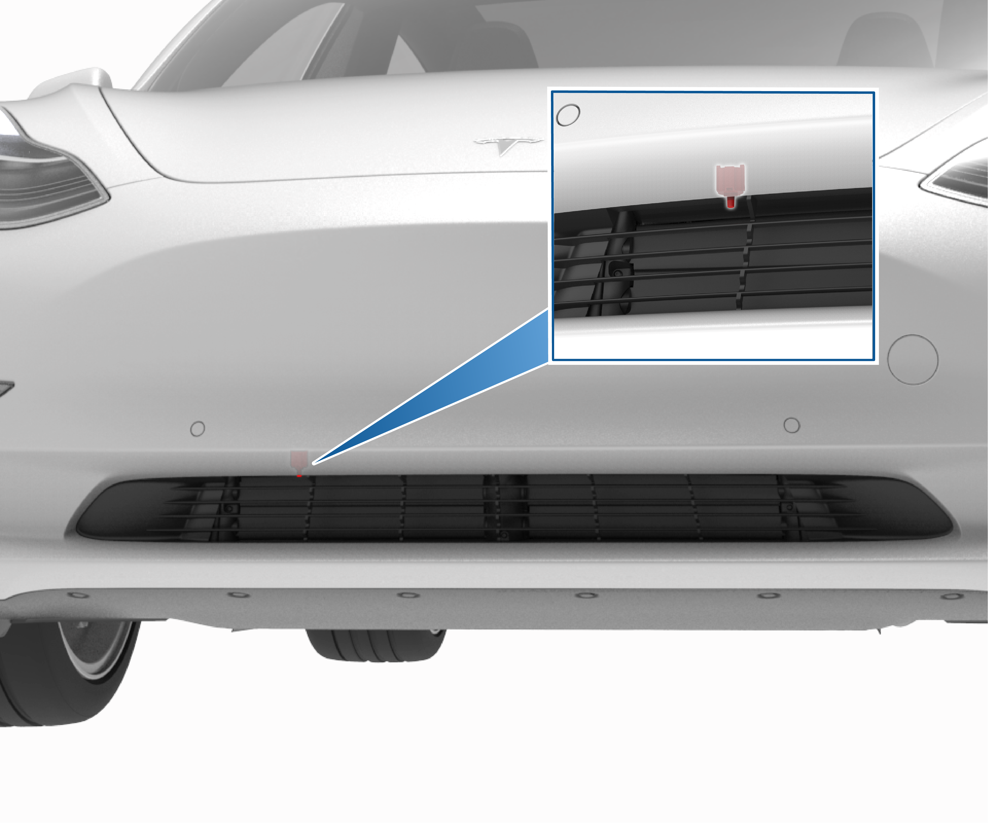
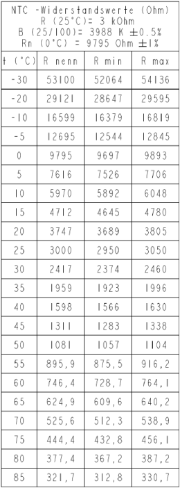
Ambient Air Temperature Sensorlink
 |
|---|
The ambient temperature sensor is a Negative Temperature Coefficient (NTC) sensor that measures the outside air temperature. The sensor is located in the right hand side of the front grille, and is connected directly to the Vehicle Controller (VC) front module.
Note
See the Ambient Temperature Sensor Connector and Resistance section for additional information.
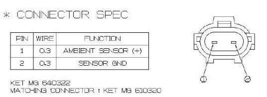
Ambient Temperature Sensor Connector and Resistancelink
 |
|---|
| Ambient Temperature Sensor Pinout |
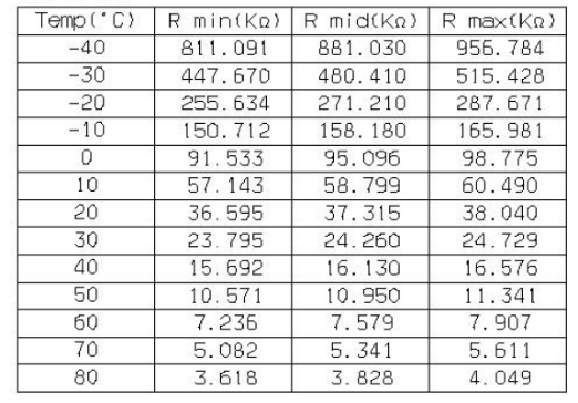 |
|---|
| Ambient Temperature Sensor Resistance |
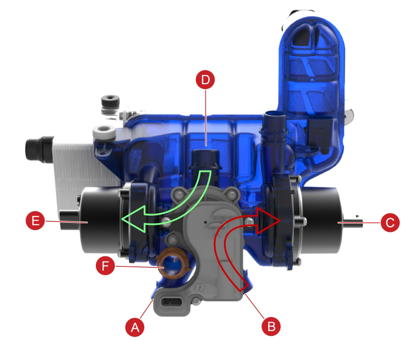
Coolant Reservoir (Superbottle)link
The coolant reservoir is mounted under the hood of the vehicle. The coolant reservoir is known as the “superbottle” because it contains many components integrated into a single coolant reservoir assembly:
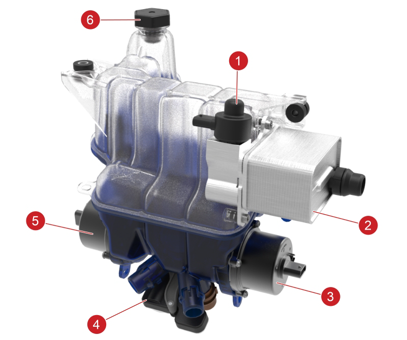 |
|---|
| 1. Chiller Expansion Valve (EXV) 2. Coolant chiller 3. Battery coolant pump 4. The 5-Way valve 5. Powertrain coolant pump 6. Coolant reservoir cap |
| Superbottle Parts |
Additionally, there are sensors for coolant temperature and level, and coolant inlet and outlet ports.
The superbottle is a flow-through de-gas bottle, where the majority of the coolant flows past the bottle, while only a small portion of the coolant flows into the bottle. The coolant that does flow into the bottle passes through a series of settling chambers that allow air to migrate out of the coolant within several minutes. When needed, air-free coolant is drawn from the reservoir. The coolant level in the reservoir should be between the MIN and MAX lines when the vehicle’s coolant is at ambient temperature.
 |
|---|
| Superbottle Port Functions |
 |
|---|
| Superbottle Coolant Pump Flow Paths |
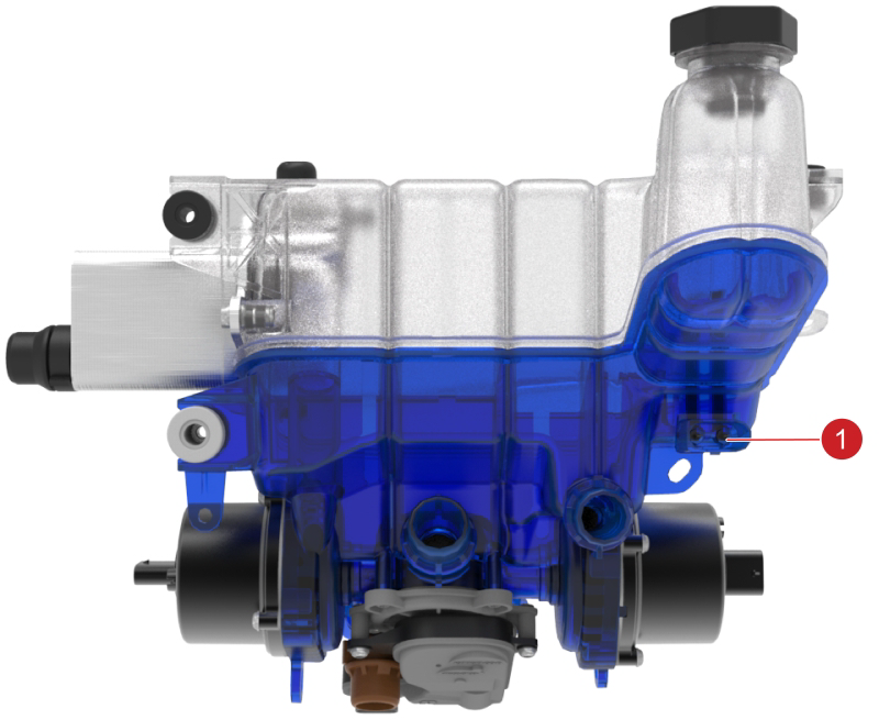
Coolant Level Sensorlink
 |
|---|
| 1. Coolant level sensor |
The coolant level sensor is a capacitive sensor that changes capacitance based on the coolant level in the superbottle. The sensor capacitance is monitored by the Vehicle Controller (VC) Front module. When the coolant level is below the MIN line on the coolant reservoir, the sensor is exposed to air and because air has a lower capacitance than coolant, the sensor measures low capacitance. When the VC Front module detects low coolant level sensor capacitance, it sets the customer facing “low coolant warning”.
The coolant level sensor is located at the rear of the superbottle on the underside, it is integrated into the superbottle and is not serviceable.
Note
See the Coolant Level Sensor Capacitance section for additional information.
Coolant Level Sensor Capacitancelink
| Coolant Level | Sensor Capacitance (nF) |
|---|---|
| Empty | 50 |
| Max | 5000 |
Note
1uF = 1000nF
Coolantlink
The coolant for the Model 3 consists of G-48 coolant, which is tinted blue. G-48 is a long-life coolant designed for high aluminum content powertrain systems and is supplied from the manufacturer pre-mixed to 50% G-48 and 50% distilled water.
Warning
Do not top off or refill the cooling system with any other type of coolant.
Coolant Specifications and Capacitieslink
-
Model 3 Coolant Type
Tesla G-48 coolant is a pre-mixed 50/50 solution of antifreeze and distilled water.
Table 2. Total Vehicle Coolant Capacity
| Battery Type | RWD | AWD |
|---|---|---|
| Long Range | 15L | 16L |
-
Model 3 A/C Compressor Oil Type and Capacity
Oil Type: Denso ND-11 or JX Nippon RB100EV oil.
Capacity: Service A/C Compressor is pre-filled with (150g) ND-11 oil.
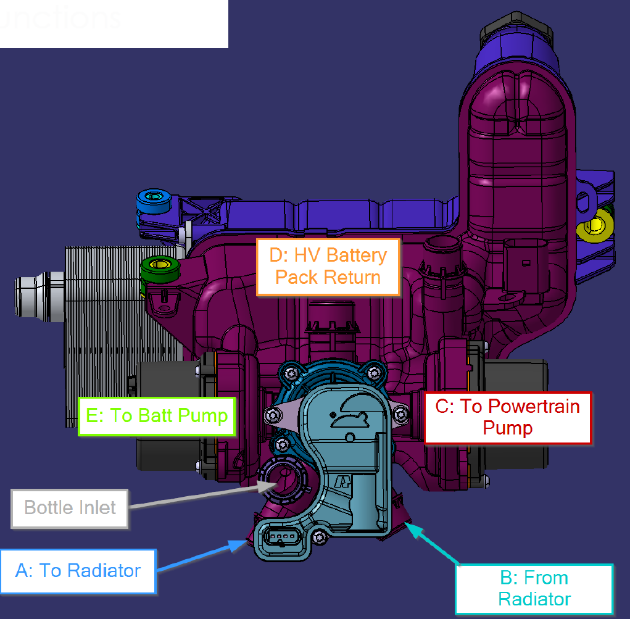
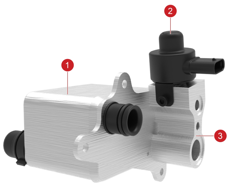
5-Way Valvelink
The 5-Way valve is integrated into the bottom of the coolant reservoir (superbottle), and it contains:
-
A valve
The valve is used to switch the coolant flow path from going through the HV Battery and powertrain in series, to diverting the coolant flow path into two parallel loops (the HV Battery loop and the powertrain loop). In addition, the valve can direct coolant flow through the radiator, or bypass the radiator.
In series mode, coolant flows through the HV Battery and powertrain in continuous loop. If the temperature of the HV Battery is below normal, heat from the powertrain can be used to passively raise the temperature of the HV Battery. The major advantage of this strategy is that is does not require additional energy to heat the HV Battery using the drive unit's active Waste Heat mode. If the temperature of the HV Battery must be managed independently, the VC Front module commands the valve to the parallel mode position.
In parallel mode, the HV Battery is isolated from the powertrain cooling loop, and can be actively cooled without being affected by powertrain temperature and fluctuations.
See illustrations below of valve operation.
-
An actuator
Controlled by the Vehicle Controller (VC) Front module, the actuator moves the valve to control the coolant flow path. The actuator contains a Hall effect position sensor that the VC Front module monitors to compare the desired valve position to the actual valve position. The actuator rotation direction is accomplished by changing the 12+VDC polarity to the actuator.
Both the valve and valve actuator are serviceable items.
Note
See 5-Way Valve Details section for additional information.
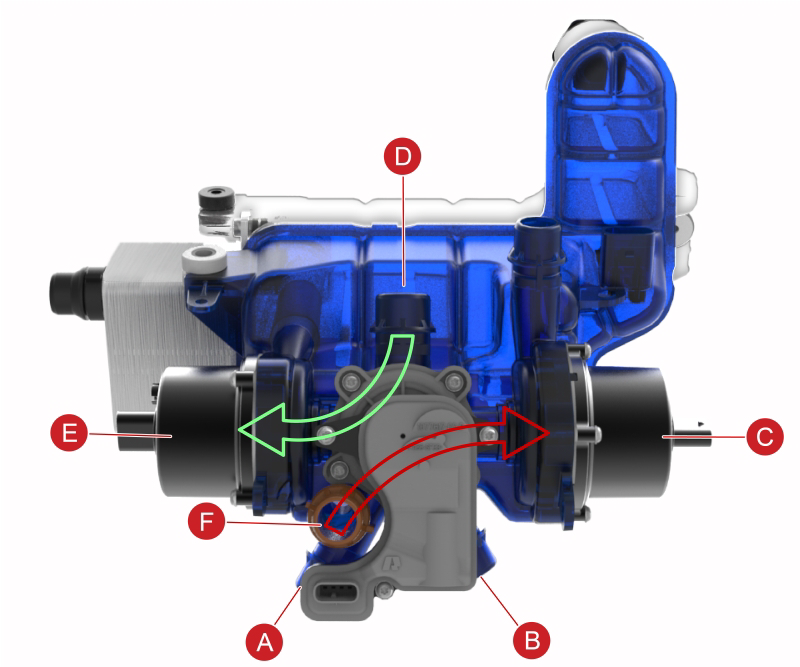
 |
|---|
| Parallel Mode / Radiator Full Flow |
| A. To radiator B. From radiator C. To powertrain pump D. From HV battery E. To HV battery F. Superbottle inlet |
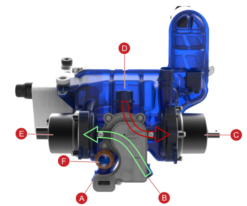
 |
|---|
| Parallel Mode / Radiator Bypassed |
| A. To radiator B. From radiator C. To powertrain pump D. From HV battery E. To HV battery F. Superbottle inlet |
 |
|---|
| Series Mode / Radiator Full Flow |
| A. To radiator B. From radiator C. To powertrain pump D. HV battery pack return E. To HV battery pump F. Superbottle inlet |
 |
|---|
| Series Mode / Radiator Bypassed |
| A. To radiator B. From radiator C. To powertrain pump D. HV battery pack return E. To HV battery pump F. Superbottle inlet |
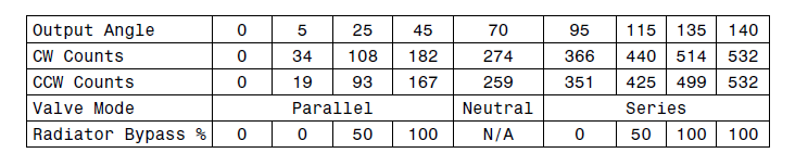
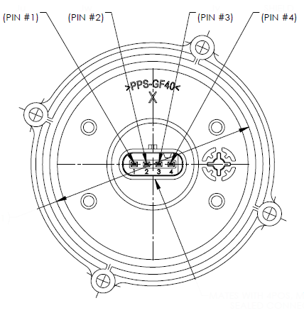
5-Way Valve Detailslink
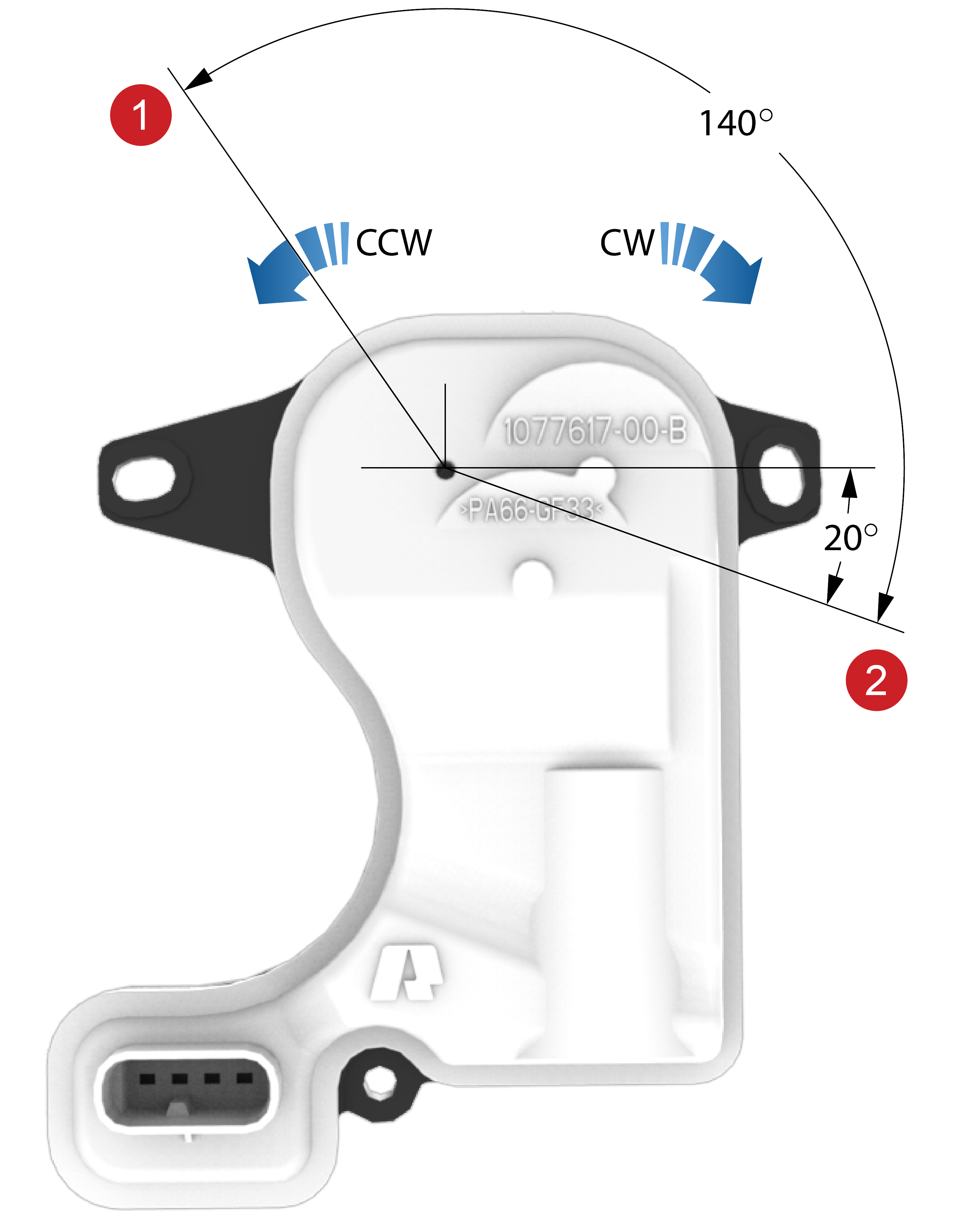 |
|---|
| 1. Counter-clockwise endstop 140 degree position reference point 2. Clockwise endstop 0 degree reference point |
| 5-Way Valve and Connector Diagram |
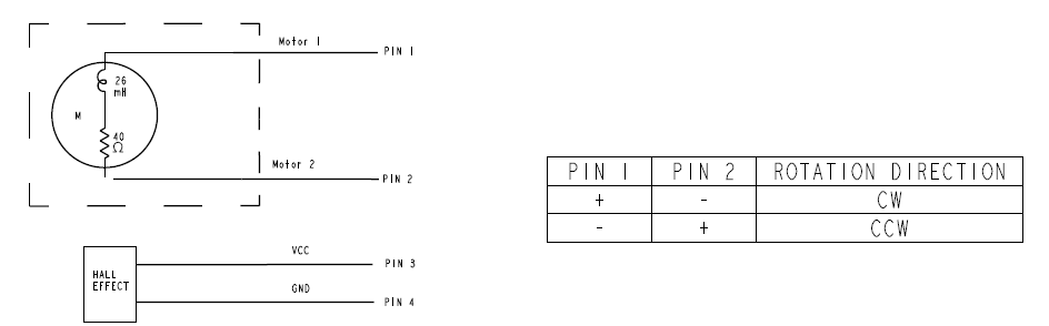 |
|---|
| 5-Way Valve Schematic and Signals |
 |
|---|
| Parallel / Series Mode and Radiator Bypass Position vs Output Angle |
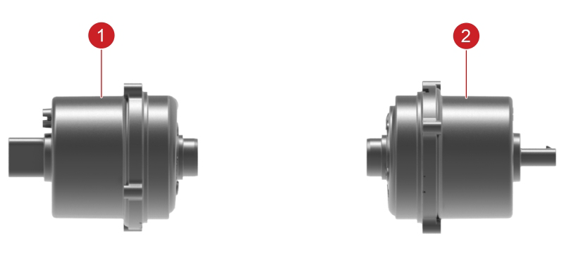
Coolant Pumpslink
 |
|---|
| 1. Battery coolant pump (left side of superbottle) 2. Powertrain coolant pump (right side of superbottle) |
Model 3 vehicles have 2 coolant pumps, one for the HV Battery and one for the powertrain.
In series mode, both the battery pump and powertrain pump work together to push coolant through the HV Battery and powertrain components.
In parallel mode:
-
The battery pump pushes coolant through the HV Battery based on temperature requests from the HV Battery Management System (BMS).
-
The single powertrain pump pushes coolant through the powertrain components to maintain them at the optimum temperature based on the temperature requests from each component.
Both coolant pumps are identical brushless centrifugal pumps designed to run between 9 and 16VDC. They are 3-phase pumps that consume up to 15A each when running a maximum duty cycle. The pumps do not have a built-in controller / driver and instead rely on a controller chip in the Vehicle Controller (VC) Front to drive the 3 phases of the pumps.
Both pumps are integrated into the superbottle, and are serviceable items.
Note
See Coolant Pump Details for additional information.
Coolant Pump Detailslink
 |
|---|
| Coolant Pump Connector Diagram |
Table 3. Coolant Pump Connector Signals
| Connector Pin | Function |
|---|---|
| 1 | Phase 1 |
| 2 | Phase 2 |
| 3 | Phase 3 |
| 4 | Shield |
Chiller and Electronic Expansion Valve (EXV)link
 |
|---|
| 1. Chiller 2. EXV Stepper Motor 3. Electronic Expansion Valve (EXV ) |
Table 4. Stepper Motor Pin Layout, 24,3 ±1.9 Ohm
| Pin Number | Pin Name |
|---|---|
| 1A | YN |
| 2C | XN |
| 3B | YP |
| 4D | XP |
The coolant chiller is used for active cooling of the HV Battery and can also support cooling the drive unit (motor, gearbox, and inverter), and power electronics. The coolant chiller is a refrigerant-to-coolant heat exchanger mounted on the superbottle.
The EXV controls the flow of refrigerant into the chiller, and is composed of only an electronic stepper motor controlled moving valve needle. The Vehicle Controller (VC) Front sends a ±12V sine wave to the stepper motor that moves the EXV to control the flow of refrigerant into the chiller.
The EXV is welded to the chiller, so they are serviced only as an assembly.
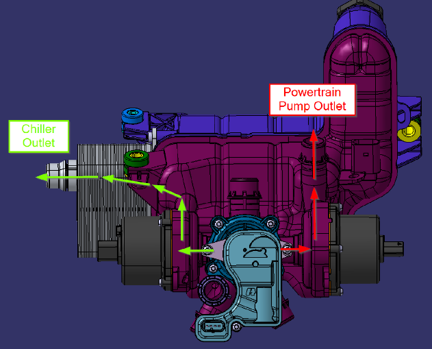
Coolant Temperature Sensorslink
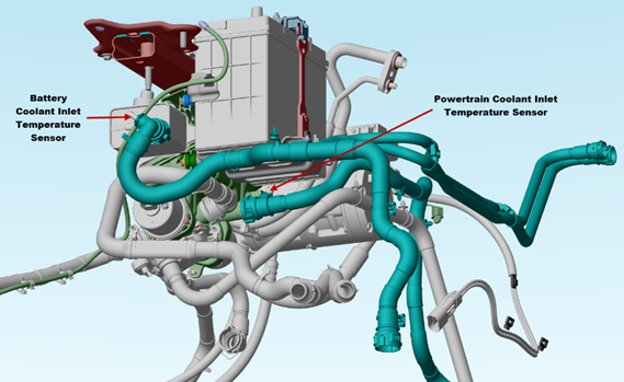 |
|---|
| 1. Battery Coolant Inlet Temperature Sensor 2. Powertrain Coolant Inlet Temperature Sensor |
There are two coolant temperature sensors:
- The battery coolant inlet sensor is located in the coolant hose at the chiller outlet, and provides the HV Battery inlet coolant temperature to the Vehicle Controller (VC) Front.
- The powertrain inlet sensor is located in the coolant hose at the powertrain pump outlet, and provides powertrain inlet coolant temperature to the Vehicle Controller (VC) Front.
These coolant temperature sensors are the same Negative Temperature Coefficient (NTC) sensor and are serviceable items.
Note
See Coolant Temperature Sensor Resistance section for additional information.
Coolant Temperature Sensor Resistancelink
Table 5. Coolant Temperature Sensor Resistance
| TEMP [°C] | Rnom [kOhms] | Tol [%] |
|---|---|---|
| -40 | 204.7 | 4.16 |
| -20 | 71.02 | 3.02 |
| -10 | 43.67 | 2.50 |
| 0 | 27.70 | 2.06 |
| 10 | 18.07 | 1.67 |
| 25 | 10.00 | 1.00 |
| 40 | 5.811 | 1.55 |
| 50 | 4.147 | 1.91 |
| 60 | 3.011 | 2.26 |
| 70 | 2.224 | 2.57 |
| 85 | 1.451 | 3.04 |
| 100 | 0.9753 | 3.46 |
| 120 | 0.5993 | 3.89 |
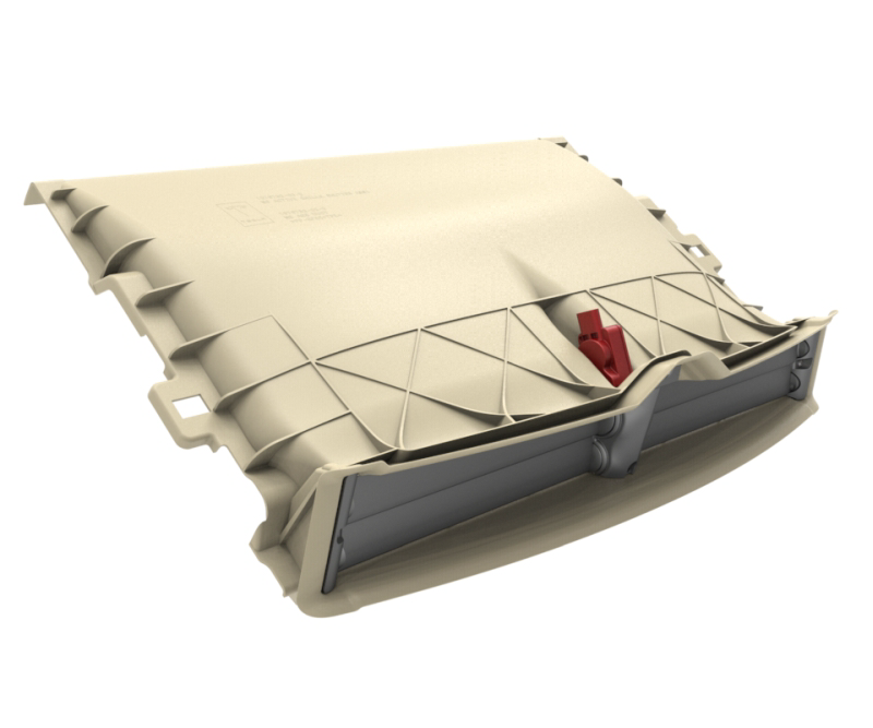
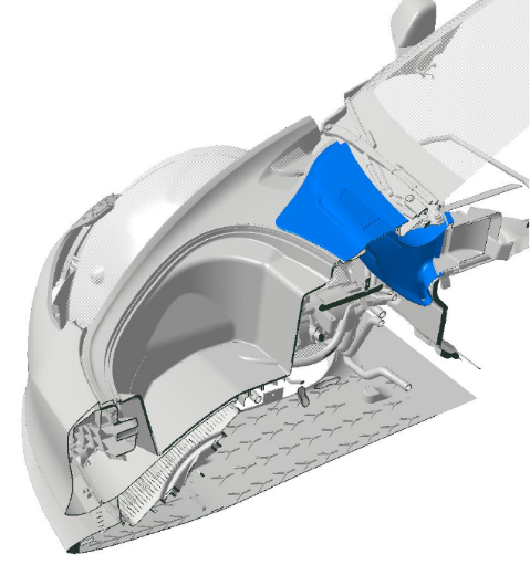
Active Shutterslink
 |
|---|
Note
The shutter actuator is shown in red.
The Model 3 has an active shutter assembly that controls the flow of ambient air to the cooling module, which includes the radiator and condenser. The system is designed to keep airflow at the minimum amount necessary for cooling. Also, minimizing the airflow can be used to reduce the time for components to reach normal operating temperature. The shutter assembly is visible from the front of the vehicle.
The active shutters are motor actuated from a single actuator and the motor is controlled via the Vehicle Controller (VC) Front, using feedback from the following sensors:
- Coolant temperature sensors
- Refrigerant temperature sensors
- Refrigerant pressure sensors
- Ambient air temperature sensor
- Vehicle speed sensor
The active shutters also minimize the vehicle’s aerodynamic drag when cooling demands are low, to reduce vehicle power requirements and increase range. The active shutters close when the vehicle is not in drive mode, but open if required when cooling the charging system during charge mode, or running the cabin HVAC in support mode.
| Ambient Air Temperature | When Driving | When Charging |
|---|---|---|
| Cold | The active shutters are closed to maximize the HV Battery warming. Aerodynamic drag is reduced to extend the vehicle driving range. | The active shutters are closed to maximize the HV Battery warming. |
| Normal | The active shutters open if the powertrain or HV Battery need to be cooled. The active shutters also open if the cabin A/C is turned ON, to provide airflow to the condenser. | The active shutters open if the HV Battery and / or charger needs to be cooled. |
| Hot | The active shutters open as the powertrain or HV Battery need to be cooled. The active shutters also open if the cabin A/C is turned ON, or for active HV Battery cooling (battery coolant chiller ON) during aggressive high speed driving. | The active shutters open if the HV Battery and / or charger needs to be cooled. The active shutters also open if the cabin A/C is turned ON, or for active HV Battery cooling (battery coolant chiller ON) during fastcharging / supercharging. |
Cabin Heating, Ventilation, Air Conditioning (HVAC) Systemlink
 |
|---|
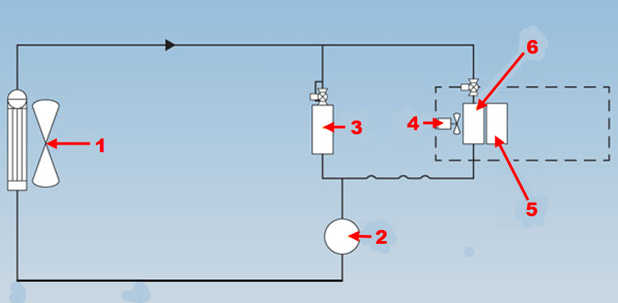
Air Conditioning (A/C) Refrigerant Cyclelink
The A/C system extracts heat from inside the vehicle and transfers it to the outside atmosphere.
The Model 3 A/C system includes an evaporator in the HVAC case, a compressor, a condenser (with integrated receiver/dryer), a battery coolant chiller, a Thermal Expansion Valve (TXV) on the evaporator, and an Electronic Expansion Valve (EXV) on the chiller. All components are connected by refrigerant lines. The refrigerant lines contain high pressure and low pressure charge ports, including high and low side refrigerant pressure and temperature sensors.
In addition to providing conditioned air inside the vehicle, the A/C system uses additional refrigerant lines to direct condensed refrigerant to the EXV on the battery coolant chiller assembly. This system controls the temperature of the HV Battery and the powertrain components.
An electric solenoid valve integrated into the evaporator TXV shuts off refrigerant flow to the evaporator when there’s no cabin HVAC demand or if the chiller demand exceeds cabin demand.
The refrigerant system is a sealed, closed-loop system filled with R-134a (North America) or R-1234yf (EMEA and APAC) refrigerant as the heat transfer medium.
A non-conductive Polyolefin Ester Oil (POE) with ND-11 specifications is added to the refrigerant to lubricate the internal components of the compressor. This oil is supplied in the compressor during manufacture. Whenever the system is discharged and / or components are replaced, refrigerant and oil must be replaced in an equivalent weight to what was removed.
Note
See the Coolant Specifications and Capacities section for refrigerant and oil information.
 |
|---|
| 1. Condenser and fan 2. A/C compressor 3. Coolant chiller and EXV assembly 4. HVAC blower motor 5. PTC cabin heater 6. Evaporator |
| A/C Refrigerant System |
The electric A/C compressor pumps refrigerant through the system, in a repetitive cycle which continues while the A/C system is operating.
- The electric A/C compressor receives the low pressure, low temperature gas from the evaporator and/or battery coolant chiller and compresses it into high pressure, high temperature vapor.
- The high pressure, high temperature vapor enters the condenser and fan assembly, which cools the vapor by transferring the heat from the refrigerant to the ambient air.
- The cooler vapor travels through the condenser, where it condenses into liquid refrigerant. As the liquid passes through a mesh filter and into the receiver/dryer inside the condenser, any moisture in the liquid refrigerant is removed by desiccant granules. If the moisture is not removed, it can freeze and prevent normal A/C operation.
- The liquid refrigerant is then transferred to the TXV or the EXV which reduces the refrigerant pressure by expanding the high pressure cool liquid to a low pressure atomized spray. The TXV regulates the flow of liquid refrigerant into the evaporator, and the EXV regulates the flow of liquid refrigerant into battery coolant chiller.
- The low pressure refrigerant spray enters the evaporator and the battery coolant chiller where it absorbs heat from the surrounding area, which causes the refrigerant to boil and then vaporize. The boiling and vaporizing of the refrigerant produces the cooling effect inside the vehicle.
- Finally, the vaporized refrigerant is drawn back into the compressor and pressurized again as described in Step 1.
Refrigerant Slimline Sealslink
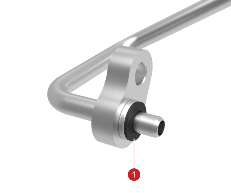 |
|---|
| 1. Slimline seal |
All A/C line connections use Slimline style seals, which are designed for one-time use. If the connection is opened, the Slimline seal must be replaced. The Model 3 uses four different sizes of Slimline seals through the A/C system.
Note
See the Slimline Seal Lookup Table section for additional information.
Slimline Seal Lookup Tablelink
Table 6. Slimline Seal Lookup Table
| Nominal Size | QPV | Locations Used |
|---|---|---|
| ⅜" | 3 | TXV (AC line side)EXV InletCondensor Outlet |
| ½" | 3 | TXV (HVAC side)Compressor OutletCondensor Inlet |
| ⅝" | 1 | TXV (HVAC side) |
| ¾" | 3 | TXV (AC line side)EXV OutletCompressor Inlet |
Cabin Temperature Sensorslink
In-Cabin Temperature Sensor
 |
|---|
The in-cabin temperature sensor is single printed circuit board (PCB) unit, where three thermistors are wired to the same PCB. Each thermistor has the same Resistance / Temperature (RT) curves, but they have different reaction times. For example, the fast reacting thermistor is used to quickly detect changes in cabin temperature, where the two slower reacting thermistors are used to determine cabin soak temperatures over extended periods of time. The lateral direction of HVAC airflow is limited to prevent air from being directed at the back of the screen and artificially heating/cooling the sensor.
The sensor is located under the instrument panel screen. Remove the lower screen bracket cover to access the sensor. The sensor is connected directly to the Vehicle Controller (VC) Right.
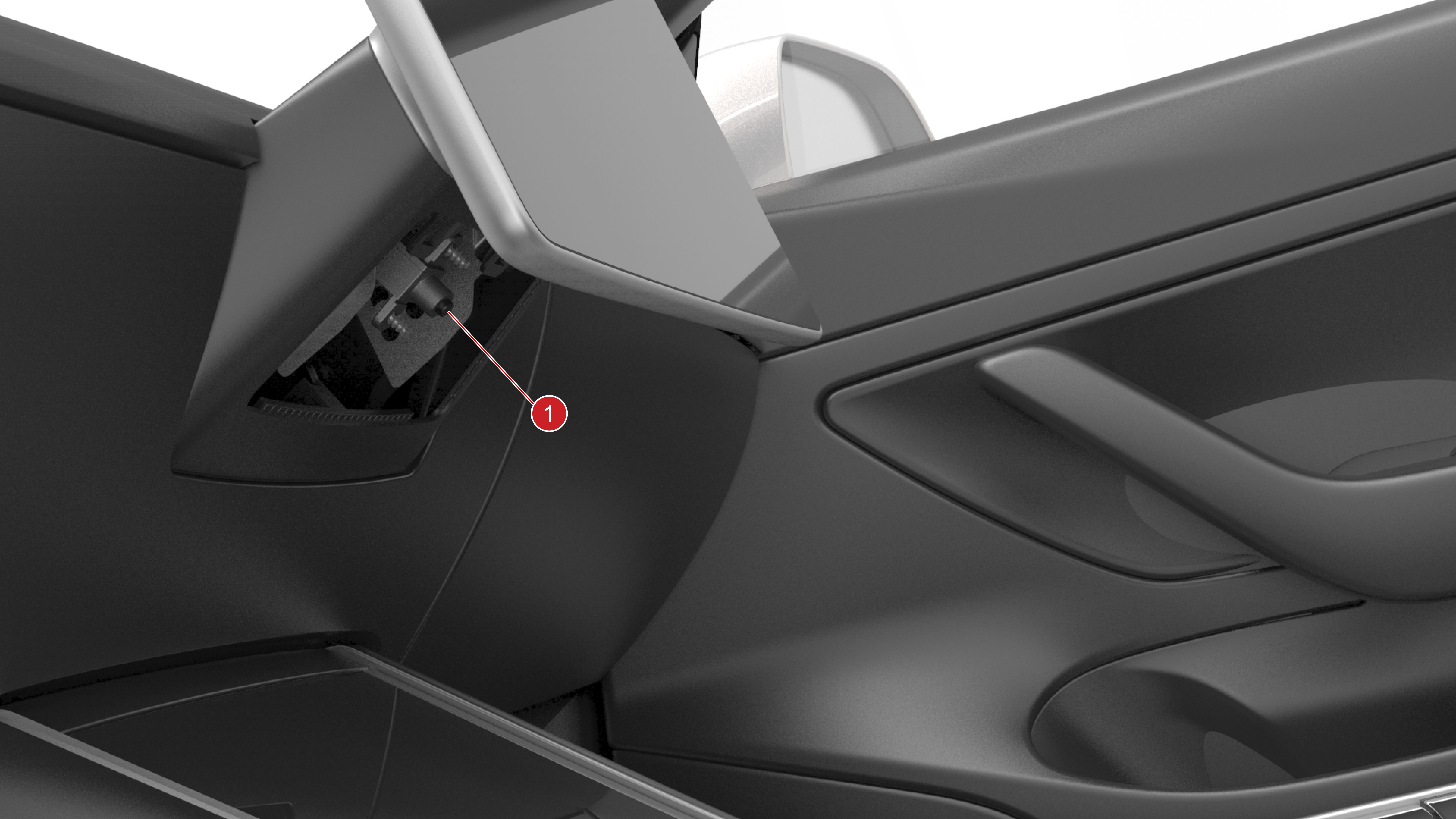
Windshield HVAC sensor assembly (Windshield temperature, humidity, solar load)
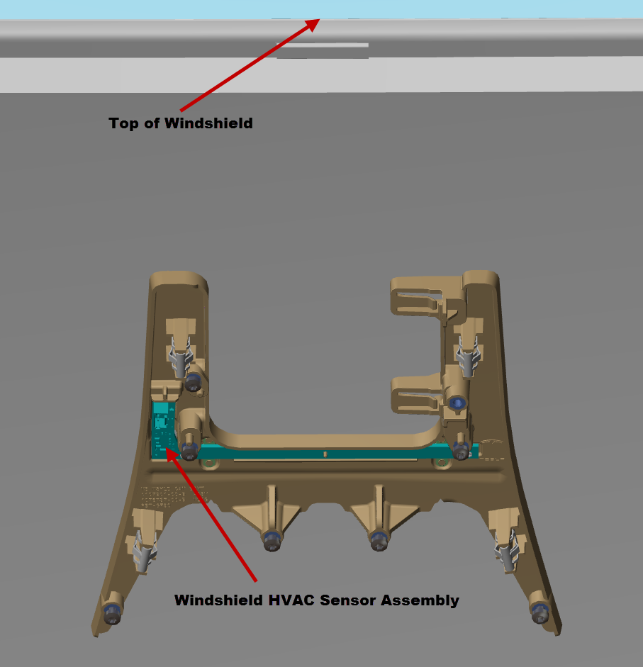 |
|---|
The windshield HVAC sensor assembly includes the windshield temperature sensor, humidity sensor, and solar load sensor. All the sensors are contained on one circuit board that is mounted to the windshield surrounding the rear view mirror. The sensors are connected directly to the Vehicle Controller (VC) Right. The VC Right uses the solar load information to estimate the heating effect on the vehicle from sunlight. It uses this input to maintain the desired cabin temperature as the solar load varies.
The VC Right also uses the humidity data from the humidity sensor for windshield fogging detection. If conditions for windshield fogging are detected, the VC Right attempts to reduce fogging by forcing fresh air, turning on partial defrost mode, and turning on the air conditioning evaporator.
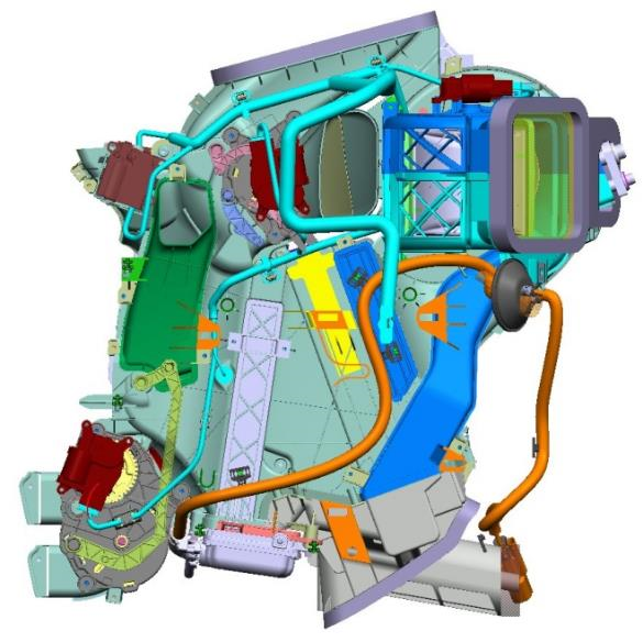
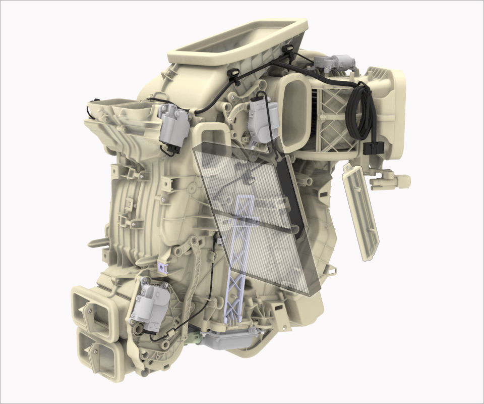
HVAC Caselink
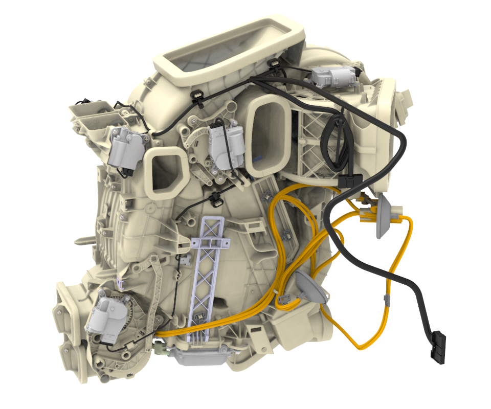 |
|---|
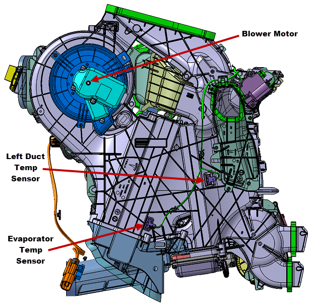
The HVAC case is located under the instrument panel and contains the following components:
- Blower motor
- Cabin filter (2-piece)
- Evaporator
- Positive Temperature Coefficient (PTC) cabin heater
- Actuators (Lower Mode, Upper Mode, Left Bleed, Right Bleed, Inlet Actuators)
- Sensors (Evaporator Temperature Sensor, Left and Right Duct Temperature Sensors)
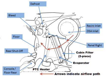
The HVAC system controls the temperature, humidity, flow volume, distribution, and quality of air within the Model 3 to achieve and maintain the conditions requested by the driver.
- In Fresh air mode, Outside Air (OSA) enters through the openings at the base of the windshield on the right hand side of the vehicle.
- In Recirculation (Recirc) air mode, the cabin air enters the HVAC case through the Recirc Inlet located above the glove box. The Inlet Actuator controls the position of the Fresh / Recirc air door allowing full Fresh, full Recirc, or a blend of both Fresh and Recirc air into the HVAC case.
 |
|---|
| HVAC Air Inlet |
Air is drawn into the HVAC case by the integral blower motor located under the center of the instrument panel. The air is then circulated as follows:
- The air is forced into the HVAC unit through the two-piece cabin filter.
- The air then goes through the evaporator, which then cools and dehumidifies the air.
- The air then goes into the Positive Temperature Coefficient (PTC) cabin heater.
- After the air has been cooled, dehumidified, and heated as necessary, it passes into the main plenum, from which is distributed.
From the plenum, the air is distributed through five primary outlets:
- Front Defrost outlet
-
Front Panel outlet
- This outlet is controlled by a single door, but is also complimented with left and right bleed outlets, which are separate from the front panel outlet. The bleed outlets are independently controlled by- actuators. -
Front Floor outlet
- Rear Console outlet
- Rear Floor outlet
Note
Rear air selection is accomplished with a single door to select between console and floor.
Airflow through the rear outlets can be shut off, while airflow through the front outlets is controlled. The mode control is performed through operation of electric actuators:
- Upper Mode Actuator, which also controls the Defrost and Front Panel
- Lower Mode Actuator
- Left Bleed Actuator
- Right Bleed Actuator
All actuators are motor controlled and have linear potentiometer output based on HVAC door position. The actuator motors operate on 12+ VDC, with an internal potentiometer which uses 5 VDC reference and 0 VDC to 5 VDC potentiometer feedback.
Note
See the HVAC Case Actuator Travel and Voltage Details section for additional information.
 |
|---|
| HVAC Case - Right Hand Side |
 |
|---|
| HVAC Case Air Distribution |
 |
|---|
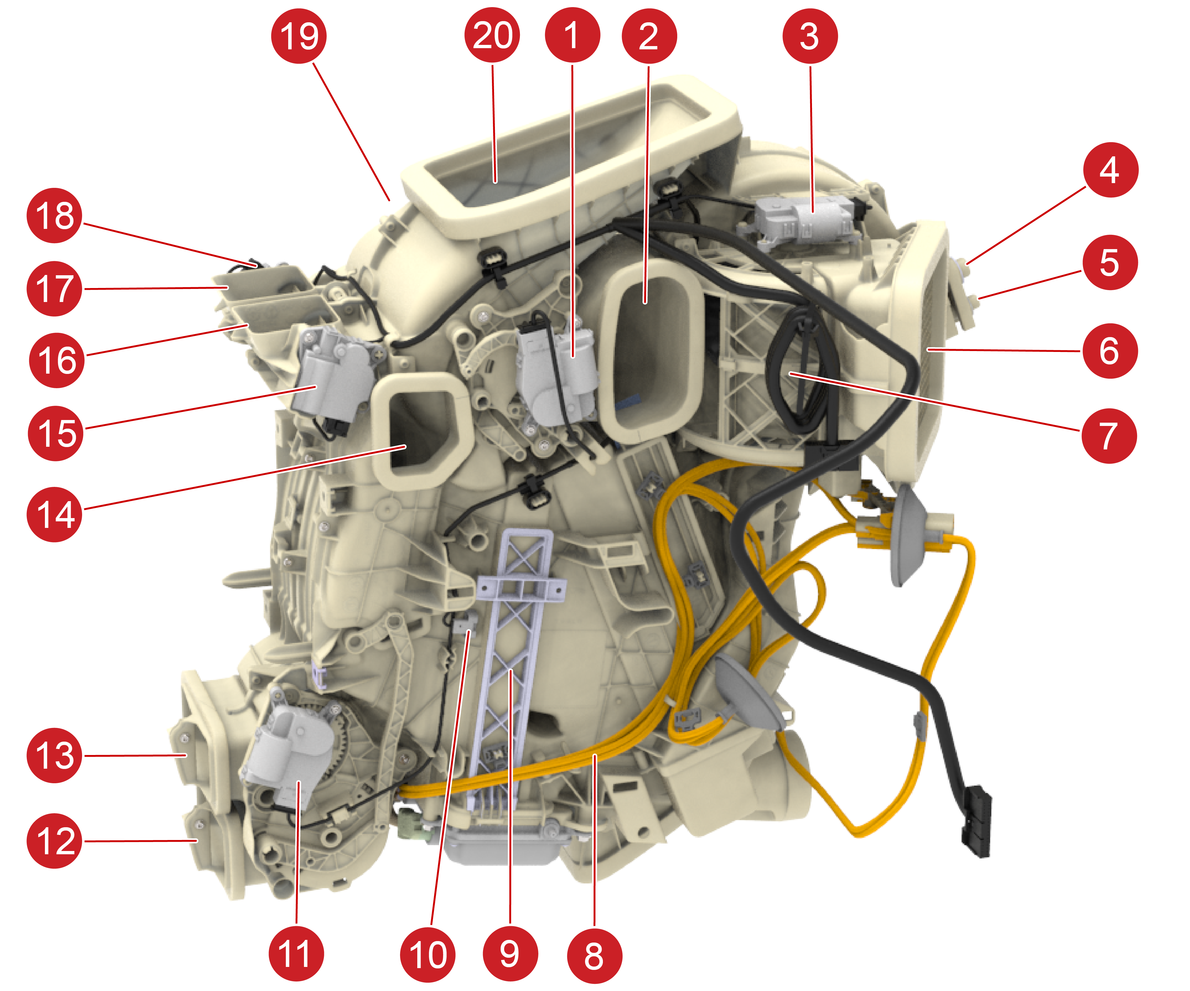
| 1. Mode - Upper 2. Panel Right 3. Inlet 4. Suction 5. Injection 6. OSA Inlet 7. Recirc Inlet 8. PTC Cabin Heater High Voltage (HV cable) 9. PTC Cabin Heater Cut-Away 10. Right Duct Temperature Sensor 11. Mode - Lowe 12. Floor Rear 13. Console (Rear) 14. Floor Front 15. Bleed Right 16. Bleed Right 17. Bleed Left 18. Bleed Left 19. Panel Left (not in view) 20. Defrost |
| HVAC Case Actuator Locations |
 |
|---|
| HVAC Case - Left Hand Side |
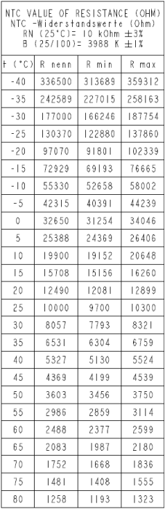
HVAC Duct Temperature Sensor Resistancelink
 |
|---|
| HVAC Duct |
Temperature Sensor Resistance
HVAC Case Actuator Travel and Voltage Detailslink
Table 7. Upper Mode Actuator and Lower Mode Actuator - Feedback Voltage
| Voltage | Actuator Travel | |||
|---|---|---|---|---|
| Mode | Upper Mode (V) | Lower Mode (V | Upper Mode (%) | Lower Mode (%) |
| Panel (1st row only) | 2.5 | 4.76 | 50% | 100% |
| Panel (1st row only) | 2.5 | 0.3 | 50% | 0% |
| Defrost | 4.8 | 4.76 | 100% | 100% |
| Defrost | 4.8 | 0.3 | 100% | 0% |
| Floor (1st and 2nd Row) | 1.43 | 2.98 | 25% | 60% |
| Floor (1st and 2nd row) + Defrost | 4.8 | 2.98 | 100% | 60% |
| Panel (1st row and 2nd row) | 2.5 | 1.4 | 50% | 25% |
| Panel (1st row only) + Defrost | 3.7 | 0.3 | 75% | 0% |
| Panel (1st row only) + Floor (1st and 2nd) | 2.5 | 2.98 | 50% | 60% |
| Panel (1st row only) + Floor (1st and 2nd row) + Defrost | 3.7 | 2.98 | 75% | 60% |
Table 8. Intake Actuator - Feedback Voltage
| Actuator Travel | Voltage |
|---|---|
| Intake (Full fresh 0%) | 1.8V |
| Intake (Recirc 100%) | 3.1V |
Table 9. Left and Right Bleed Actuator – Feedback Voltage
| Application | Shut Off | Full Open |
|---|---|---|
| Left Bleed Actuator | 0.7V | 4.3V |
| Right Bleed Actuator | 4.4V | 0.8V |
Table 10. Left and Right Panel Vane Actuator
| Application | Actuator Position | Voltage Feedback (reference) |
|---|---|---|
| Left Panel Actuator | Full Right | 0.631V |
| Full Left | 2.781V | |
| Right Panel Actuator | Full Right | 2.725V |
| Full Left | 0.793 |
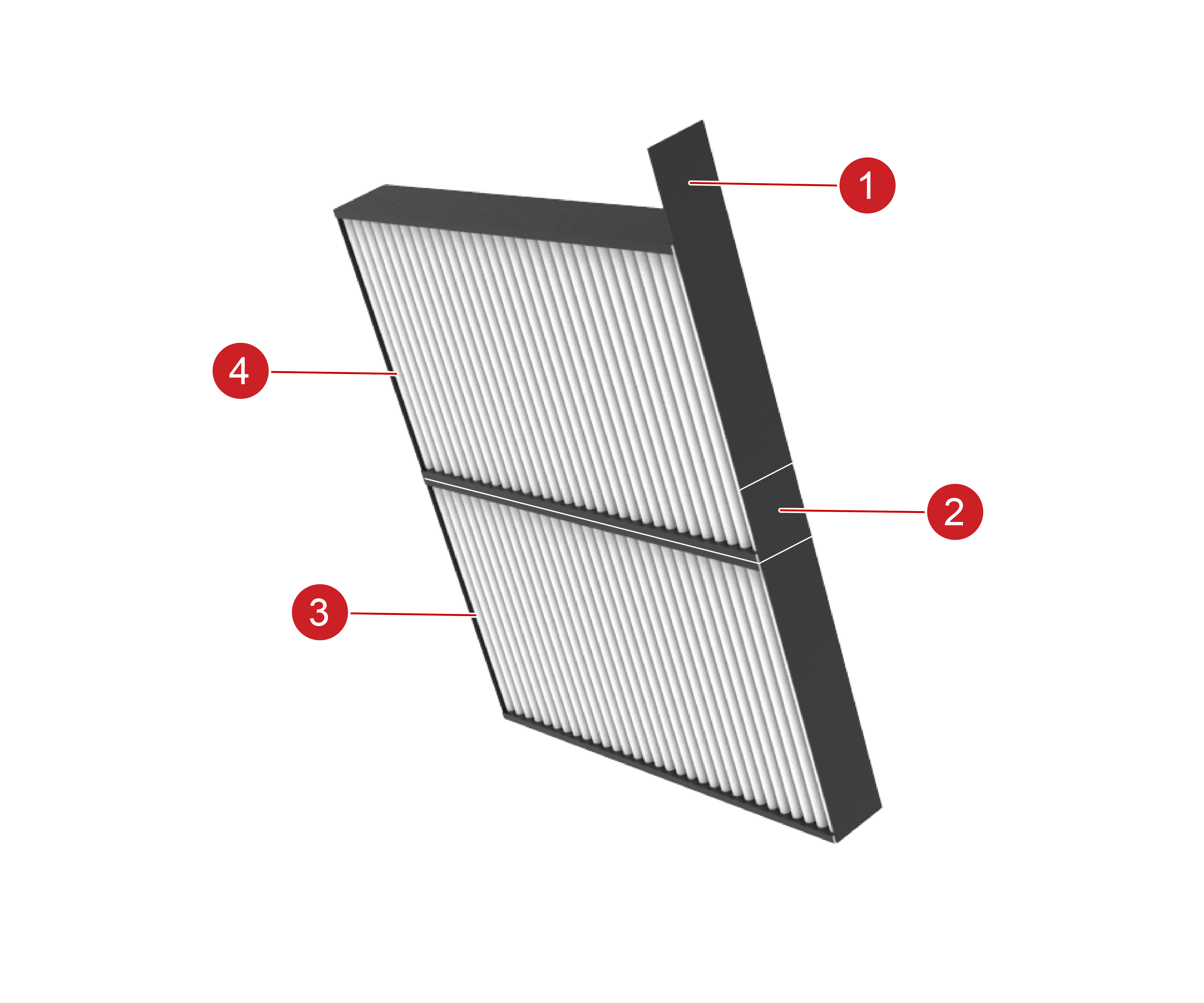
Cabin Filterslink
 |
|---|
 |
|---|
| 1. Removal Pull Tab 2. Removal Pull Tab 3. FIlter A 4. Filter B |
The Model 3 has two tandem cabin air filters located in the HVAC case.The air filters are identical combination (gas / particle) media filters. Both air filters can be accessed by removing a cover on the right side of the HVAC case and using the pull tabs to slide the air filters out of the HVAC case. Filter B is removed first from the opening at the top of the HVAC case, followed by Filter A. Installation is the reverse of the removal procedure making sure both pull tabs are folded down over Filter B making them accessible for future filter removal.
Evaporatorlink
 |
|---|
| 1. Evaporator Low Pressure Outlet 2. Evaporator High Pressure Inlet |
The evaporator is integrated into the HVAC case and cannot be removed from the HVAC case, which is located under the dash.
High pressure, low temperature refrigerant changes from liquid to vapor at it enters the evaporator, and absorbs large quantities of heat as it changes state. As the air passing through the evaporator cools, moisture in the air condenses on the evaporator surface, drying the air that is delivered to the interior of the Model 3.
Excess moisture from the evaporator collects in the bottom of the HVAC case and drains through a port located at the lowest portion of the HVAC case. A hose is attached to the port, and this hose exits through the bulkhead, allowing the condensed water to drain outside the vehicle.
The inlet and outlet pipes of the evaporator are routed through the firewall, providing a fixing point for the evaporator TXV. A foam seal surrounding the TXV provides an air and water seal at the opening in the firewall.
Evaporator Outlet Temperature Sensor Resistancelink
 |
|---|
| Evaporator Outlet Temperature Sensor Resistance |
HVAC Blower Assemblylink
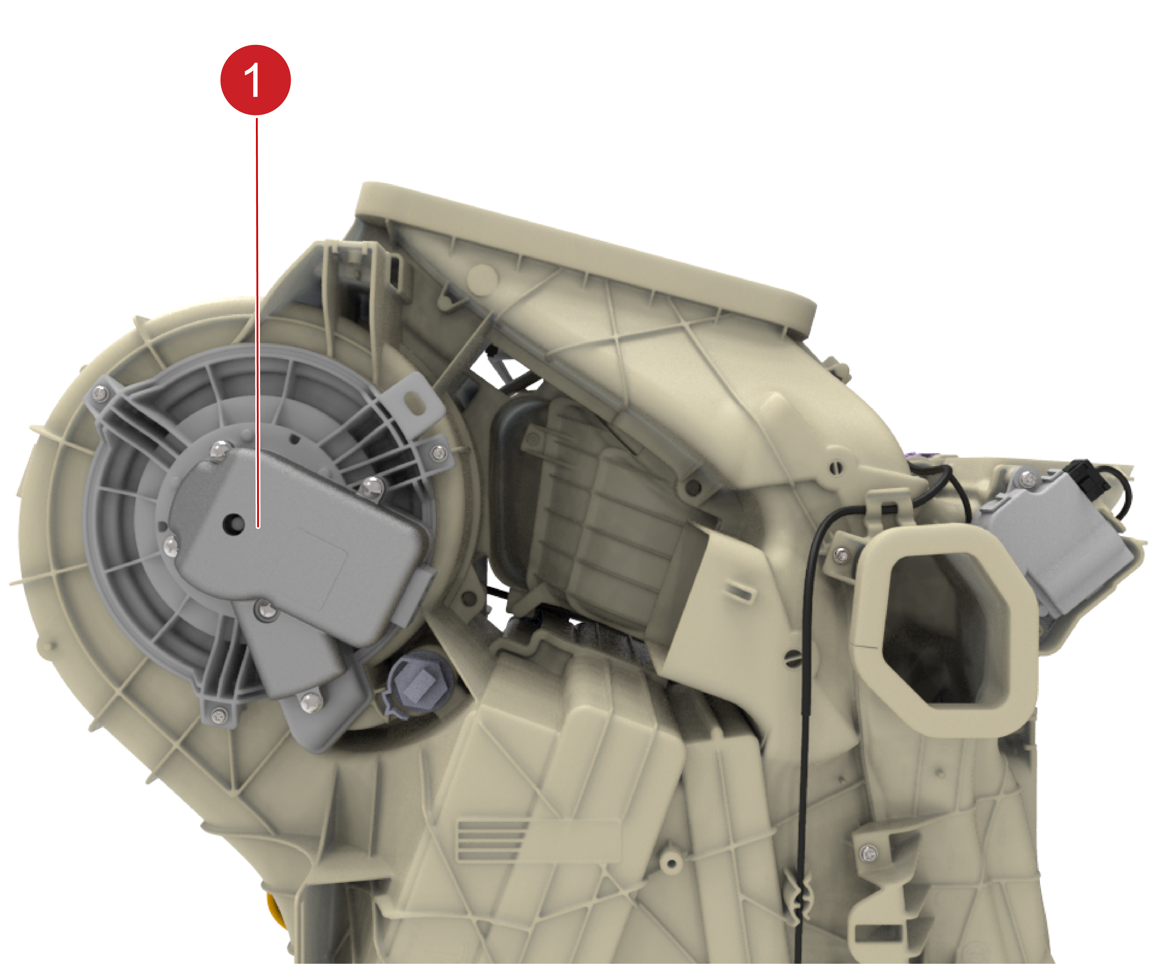 |
|---|
| 1. Blower Motor |
The HVAC case blower motor is a maintenance free, 3-phase BrushLess AC (BLAC) motor. The motor speed is controlled by the Vehicle Controller (VC) Left, which varies the AC voltage (12V battery) to each of the 3-phases in the motor. Maximum motor operating current is 34A and the motor bearings are lubricated for life. The motor is permanently attached to the fan scroll, creating a blower assembly, which is serviceable from the HVAC case.
Note
See HVAC Blower Motor Connector Details section for additional information.
HVAC Blower Motor Connector Detailslink
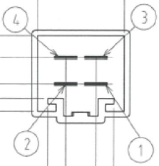 |
|---|
| HVAC Blower Motor Connector Diagram |
Table 11. HVAC Blower Motor Connector Signals
| Pin | Function |
|---|---|
| 1 | Phase 1 Power |
| 2 | Phase 2 Power |
| 3 | Phase Ground |
| 4 | Phase 3 Power |
PTC Cabin Heaterlink
 |
|---|
| 1. PTC Cabin Heater 2. Cut-Away Access Panel |
The PTC cabin heater is a high voltage device using ceramic heating stones as resistors. The electrical resistance of the stones increases as their temperature rises, providing a mechanism to prevent overheating. The heater consists of a heating matrix made up of heating stones / rods, a conductive plate, aluminum fins, and a controller in a housing.
The controller is mounted to the matrix and supplies the high voltage power to six heating stones / rods. The controller uses six sets of Insulated Gate Bipolar Transistor (IGBT) circuits to switch the DC power. A pulse width modulated circuit from the integrated controller provides variable power to regulate the amount of heat generated. Maximum heater output is ~7 kW at maximum airflow.
The PTC cabin heater is on the 500K Vehicle Bus and commanded by the Vehicle Controller (VC) right.
PTC cabin heater replacement requires the access panel to be cut away from the HVAC case. Refer to the Service Manual for replacement details. Replacement PTC cabin heaters should come with a service cover and cover fasteners to capture the replacement heater after installation.
Note
See the PTC Cabin Heater Connector section for additional information.
PTC Cabin Heater Connectorlink
 |
|---|
| Low Voltage Connector Pinout |
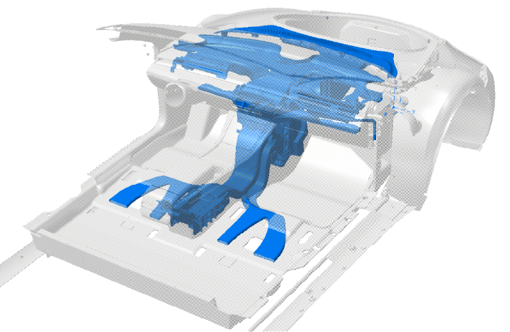
Cabin Air Distributionlink
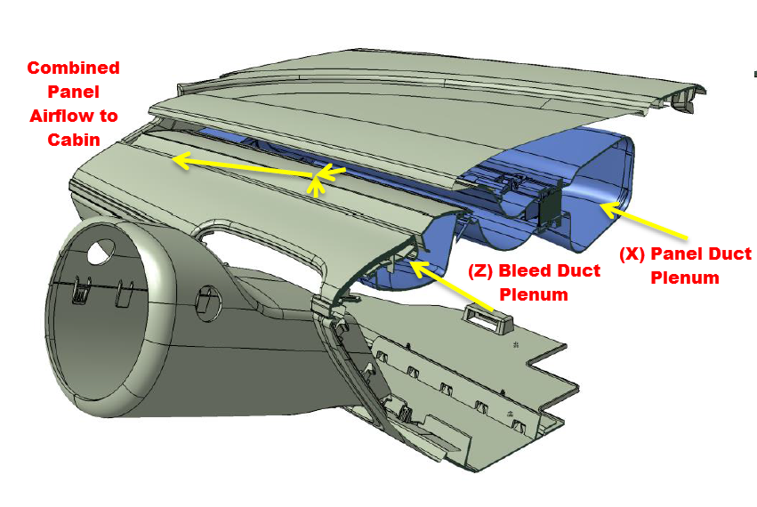
The conditioned air exits the HVAC case through the right / left Panel Ducts and right / left Bleed Ducts. The right and left Panel Ducts feed the Panel Duct Plenum, which is located in the instrument panel. The right and left Bleed Ducts feed the Bleed Duct Plenum, which is also located in the instrument panel. The Panel Duct Plenum provides airflow in the (X) direction, while the Bleed Duct Plenum provide airflow in the (Z) direction. Both the (X) and (Z) airflows meet outside the instrument panel to provide a combined panel airflow to the cabin.
 |
|---|
| Instrument Panel Ducts |
The airflow from the Panel Duct in the (X) direction is mostly constant, while the airflow from the Bleed Duct in the (Z) direction can be varied to provide a wide range of airflow that can be directed at the cabin occupants from their waist to their upper head.
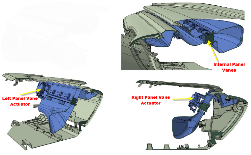
Driver and passenger side-to-side airflow adjustment is provided by panel vanes and actuators hidden inside the left side and the right side of the instrument panel.
 |
|---|
| Instrument Panel Duct Actuators |
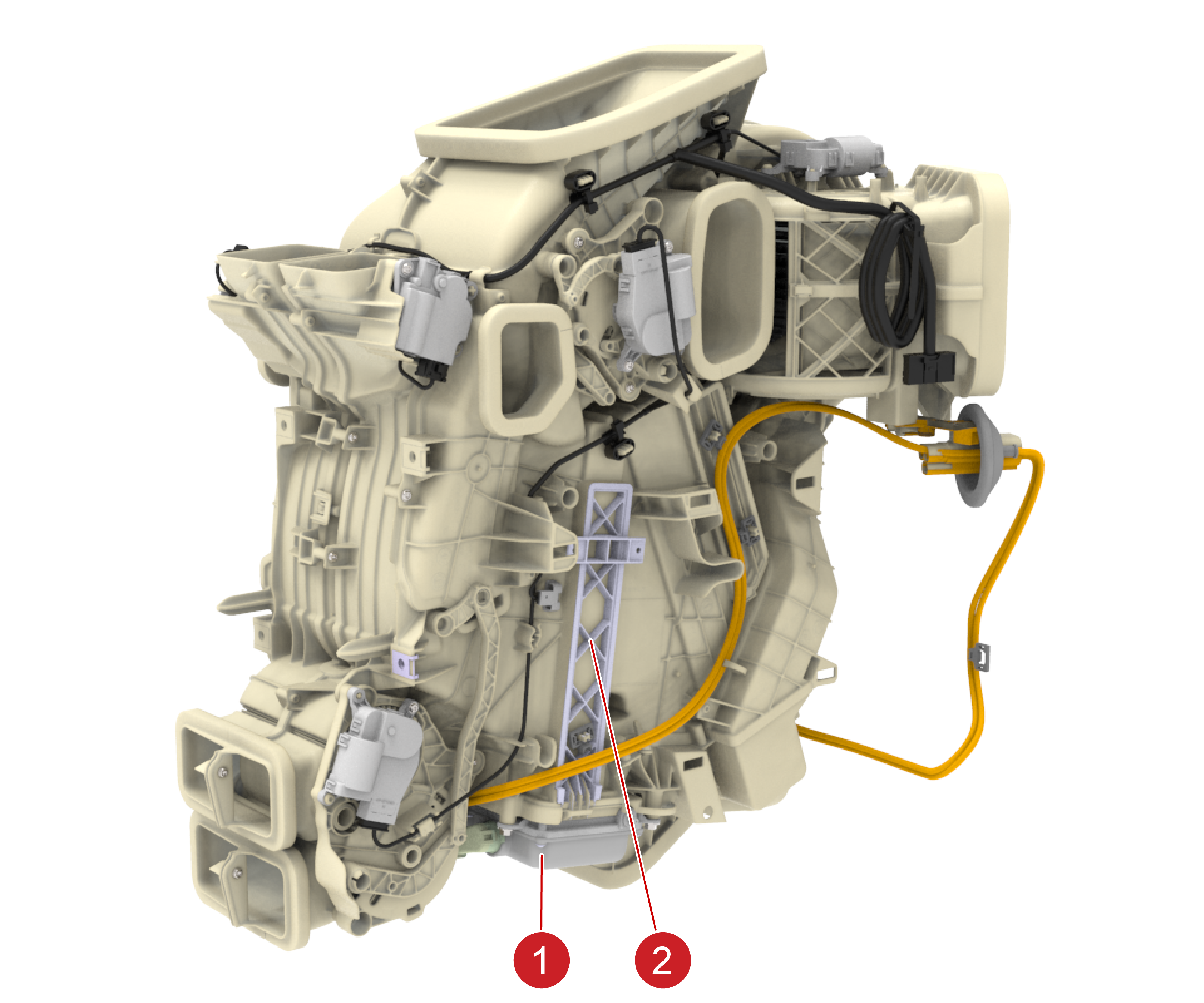
A/C Compressorlink
 |
|---|
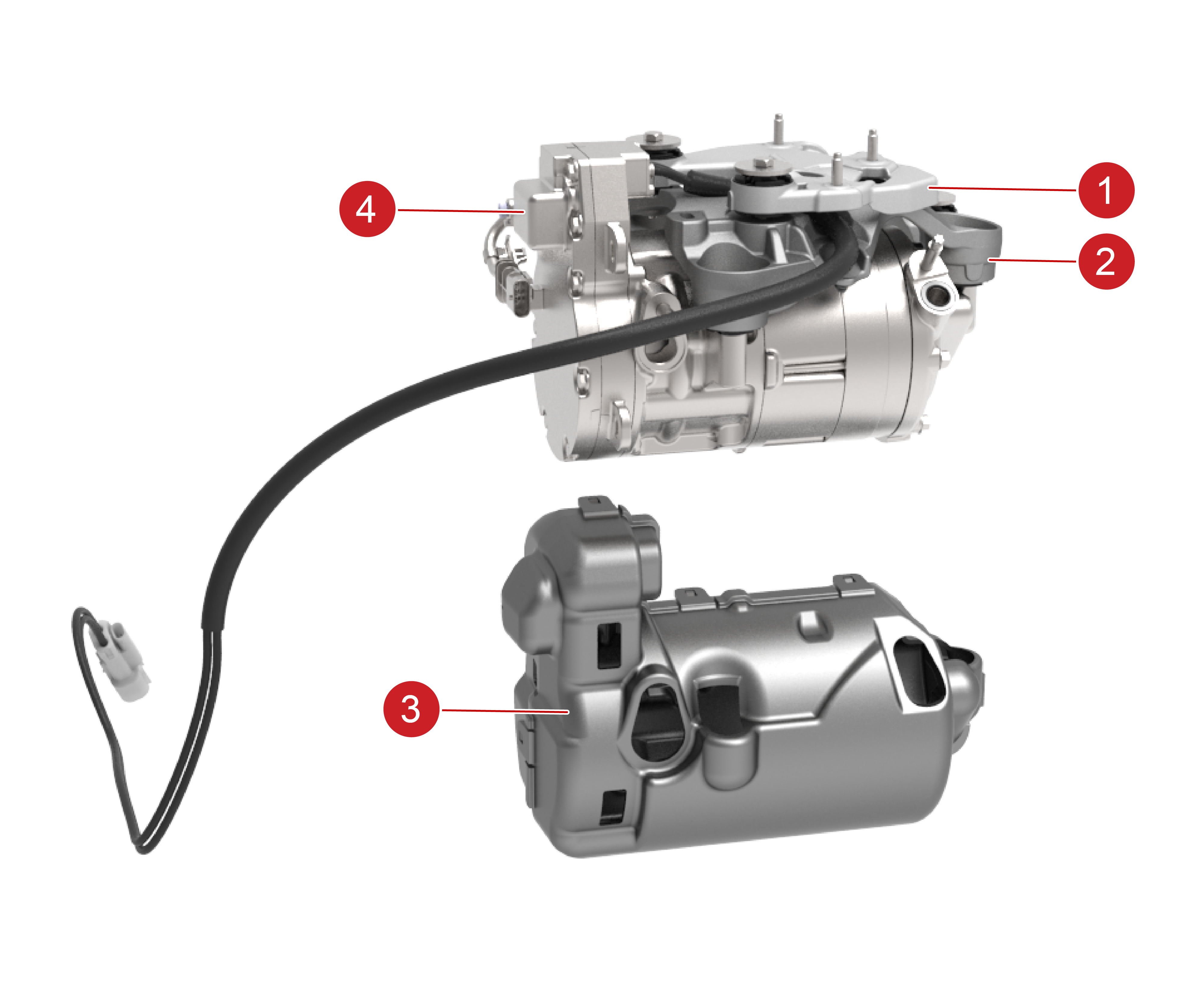
| 1. Upper Bracket 2. Lower Bracket 3. Compressor NVH Cover 4. Air Conditioning Compressor |
The A/C compressor is mounted under the hood on the strut tower brace (thermal beam) using upper and lower brackets. The brackets have rubber mounts to the compressor and the thermal beam to reduce noise, vibration, and harshness (NVH). To further reduce NVH, the compressor is equipped with an NVH cover.
The compressor is a high voltage (HV) electric Direct Current (DC) scroll type pump with a maximum rotational speed of 11,000 rpm. The Model 3 compressor has high capacity to provide better cabin cooling and fast supercharging.
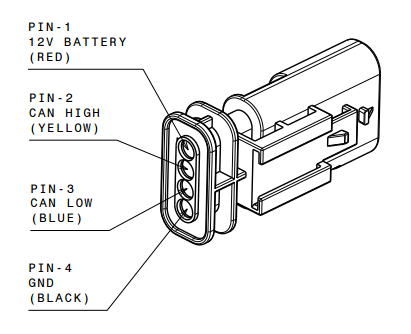
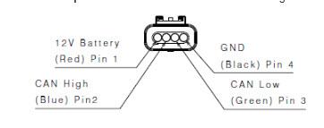
The compressor has two connectors, one for low voltage and one for high voltage. Communication with the Vehicle Controller (VC) Front is via 500K CAN bus. The low voltage connector is a four-pin connector. The signal / wires used are 12V Power, Ground, CAN (+), and CAN (-).
 |
|---|
| A/C Compressor 12V Connector |
The compressor operates in any normal range of HV Battery State-of-Charge (SOC). The compressor inverter converts the CAN signal from the VC Front into a motor drive speed. The compressor’s internal 12V power supply is generated from the HV input. The low voltage harness connections to the vehicle are used only for communication. If HV is not present at the compressor, there is a no communication response.
HV to the compressor is supplied directly from the HV junction located under the second row seat Ancillary Bay. The compressor HV fuse is also located under the second row seat Ancillary Bay. The compressor High Voltage InterLock (HVIL) connection is built into the HV connector at the HV junction.
Note
The compressor contains non-conductive POE lubricating oil meeting ND-11 specifications. The compressor must be kept upright at all times to retain this oil in the sump.
Warning
ND-11 refrigerant oil is the only approved compressor oil for a Model 3 A/C compressor. Any oil that is not designated ND-11 might affect the compressor bearing life, and might also affect the dielectric strength of the motor, potentially causing HV isolation issues, voiding the compressor warranty.
A/C Condenserlink
 |
|---|
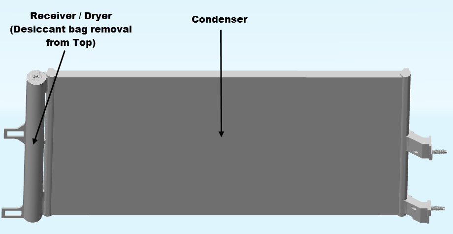
Condenser
The Model 3 has a single A/C condenser. The refrigerant enters the condenser as gas refrigerant and exits the single condenser as sub-cooled refrigerant.
Heat is transferred from the refrigerant to the air flowing through the condenser. The airflow may be caused by vehicle movement or by the operation of the condenser fan.
Receiver Dryer
The receiver dryer’s main function is to remove moisture and contaminants from the refrigerant, but it also acts as a temporary reservoir for liquid refrigerant. This reservoir of refrigerant is used to accommodate changes in heat load at the evaporator. Any moisture in the refrigerant is removed as it passes through a desiccant bag in the receiver dryer. The refrigerant is then passed to either the TXV on the evaporator or the EXV on the battery coolant chiller.
Without the receiver dryer, moisture in the A/C system may form ice in the TXV or EXV, restricting the flow of refrigerant in the system. The desiccant bag and the desiccant filter are housed in the receiver dryer located in the tank on the left end of the condenser. To simplify desiccant bag replacement, the desiccant bag and filter can be removed from the top of the vehicle.
Note
The desiccant bag in the receiver dryer is a serviceable item and must be replaced whenever the system has been open to ambient air for an extended time or when an A/C system leak is repaired.
The desiccant bag also contains a fluorescent leak dye pellet which dissolves when it comes in contact with refrigerant. The dye is then dispersed throughout the refrigerant system when the A/C compressor is operating. The leak dye helps locate the source of refrigerant leaks and is the only refrigerant dye approved for the Model 3.
Condenser Fanlink
 |
|---|
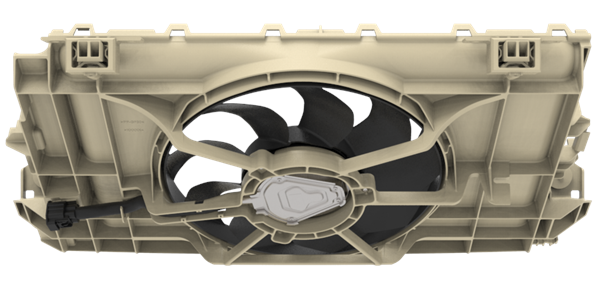
If refrigerant cooling or radiator coolant cooling is requested when the vehicle is stationary or traveling at low speeds, the fan mounted on the condenser is activated to increase the airflow through the condenser and radiator. The additional airflow increases the heat transfer from the condenser and radiator to the air.
The Model 3 uses a single condenser fan assembly, made up of the fan motor, the fan, and the fan shroud. The fan motor is a maintenance-free, 3-phase BrushLess AC (BLAC) motor, and it's speed is controlled by the Vehicle Controller (VC) Front controller, which varies the AC voltage (12V battery) to each of the 3-phases in the motor.
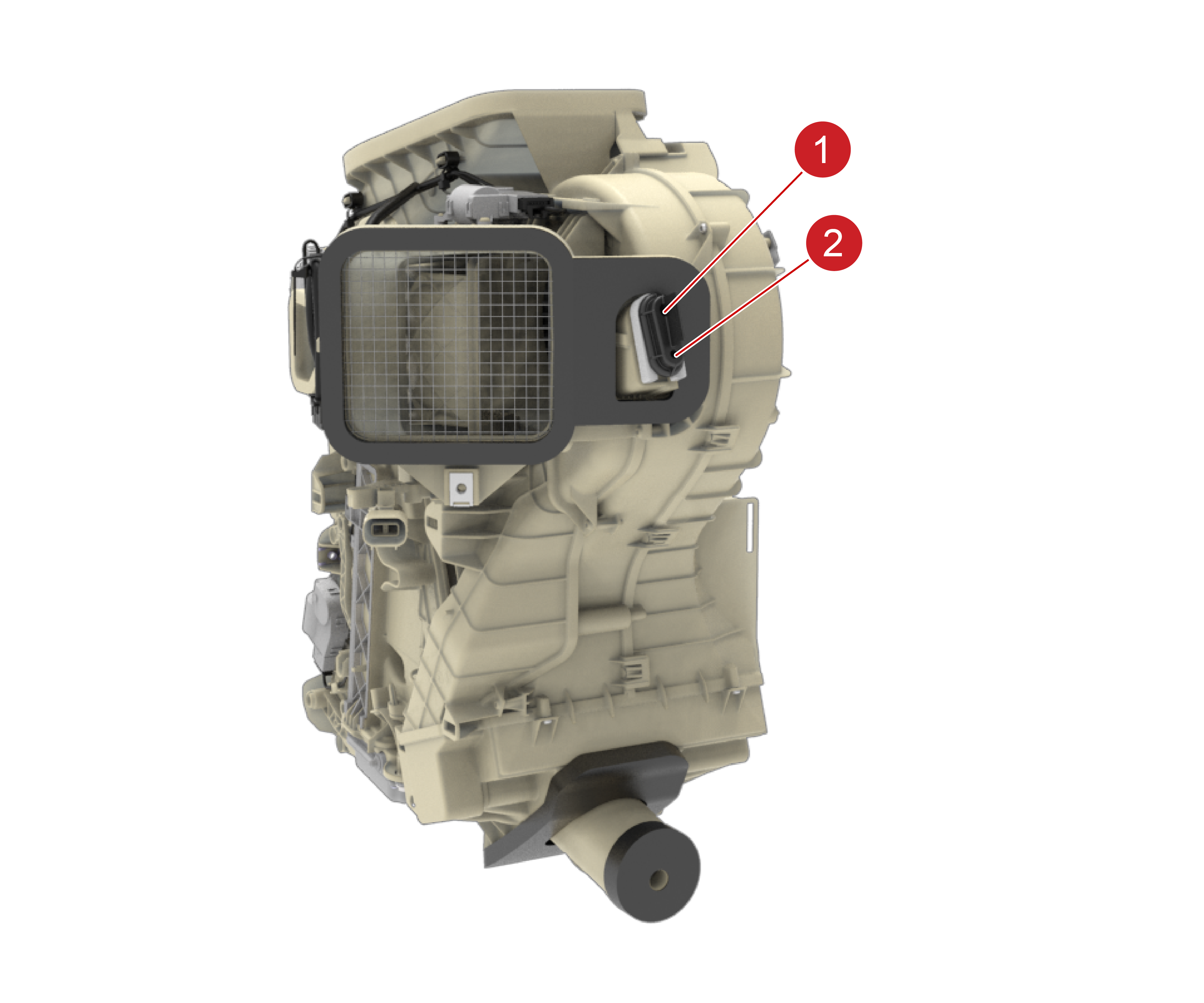
Refrigerant Temperature and Pressure Sensorslink
 |
|---|
| 1. Refrigerant Suction Sensor 2. Refrigerant Discharge Sensor |
There are two sensors to measure the temperature and pressure of the refrigerant:
- The suction sensor is located on the low pressure line coming from the chiller, and it measures the temperature and pressure of refrigerant on the low pressure side of the system.
- The discharge sensor is located in the high pressure line at the compressor outlet, and it measures the temperature and pressure of refrigerant on the high pressure side of the system.
Both sensors communicate directly to the Vehicle Controller (VC) Front, and are used to provide system response to control the compressor, condenser fan speed, and the EXV position. Both sensors use the same electrical connector and mechanical interface to the A/C line. Despite these mechanical similarities, the pressure transducer calibrations are unique to the sensor and therefore the sensors are NOT interchangeable.
Warning
There are no Schrader valves under the refrigerant sensors. Refrigerant must be removed from the system before removing any refrigerant sensor.
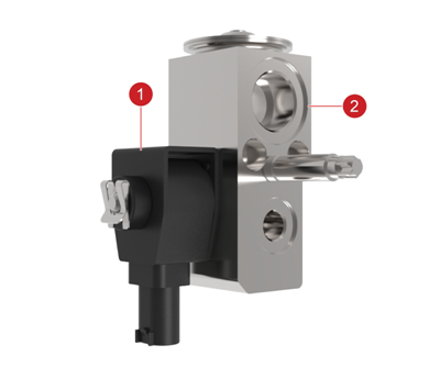
Thermal Expansion Valve (TXV)link
 |
|---|
| 1. TXV Solenoid valve 2. TXV Thermal valve |
| Model 3 Thermal Expansion Valve (TXV) |
The TXV is attached to the HVAC evaporator. The TXV is composed of two parts, a solenoid valve and a thermal valve:
-
The solenoid valve diverts refrigerant to prioritize cooling either the HV Battery chiller or the cabin air flow.
The Model 3 solenoid valve is normally open, and the Vehicle Controller (VC) Front sends 12V to close the solenoid valve when chiller demand takes priority over cabin cooling. By comparison, the Model S and Model X solenoid valve is normally closed and the Vehicle Controller (VC) opens the solenoid valve when chiller demand takes priority over cabin cooling.
-
The thermal valve regulates the quantity of refrigerant flow into the evaporator in accordance with the heat transfer required by the air passing through the evaporator. The valve closes at low outlet temperatures and opens at high temperatures to allow more refrigerant to flow through the TXV and into the evaporator.
The thermal valve senses refrigerant temperature and pressure at the TXV inlet and outlet, and it opens and closes based on the difference in temperature. The valve also uses a tunable spring at the bottom of the valve housing. The spring ensures that all liquid refrigerant vaporizes before exiting the evaporator.
Refrigerant Lineslink
Aluminum and rubber refrigerant line assemblies connect system components. Seals between the connections ensure a secure seal. To maintain similar rate of flow through the system, the diameter of the refrigerant lines varies to suit the low pressure / low temperature and the high pressure / high temperature sections. Larger diameter lines are used on the low pressure / low temperature section and smaller diameter lines are used on the high pressure / high temperature section.
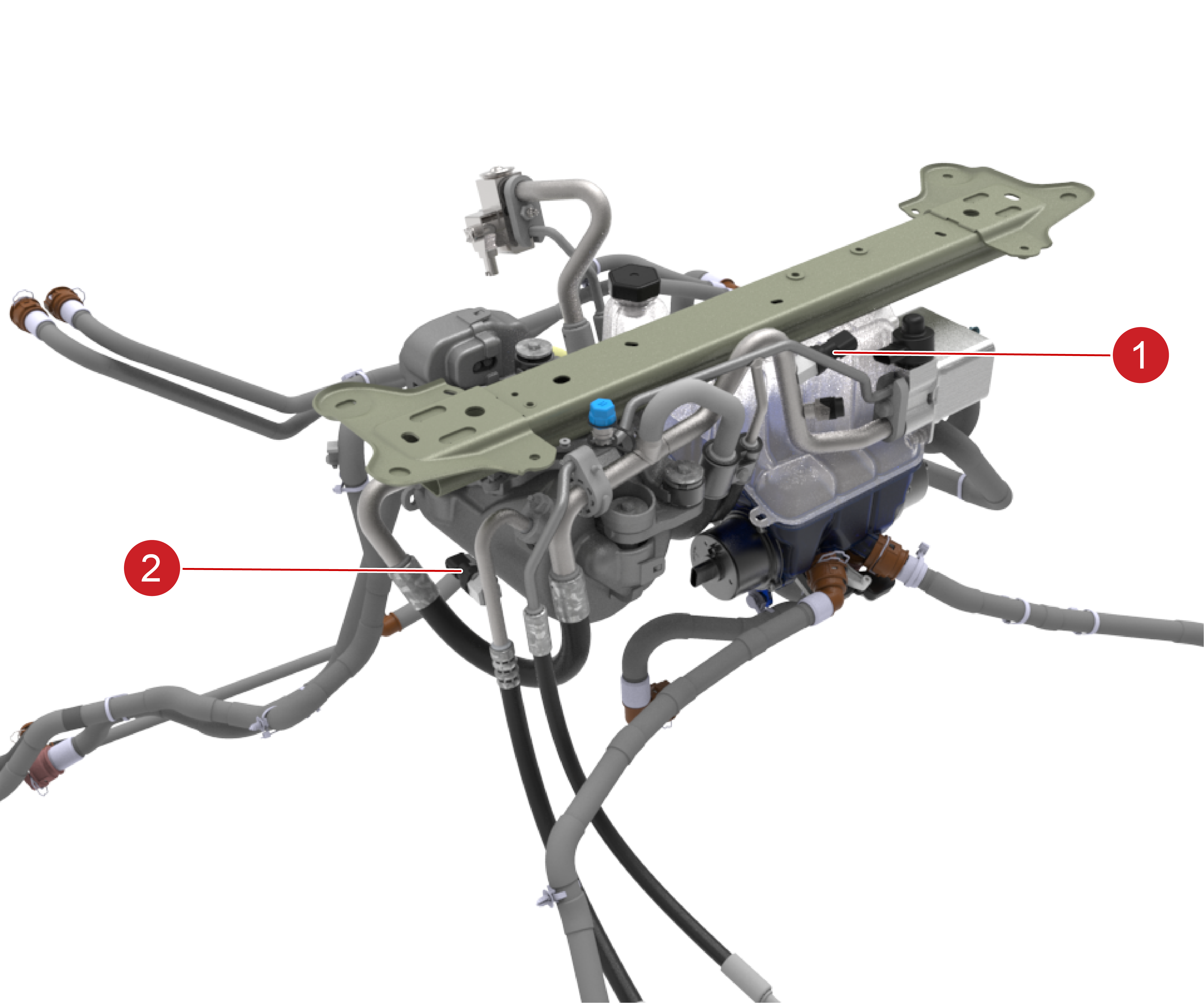
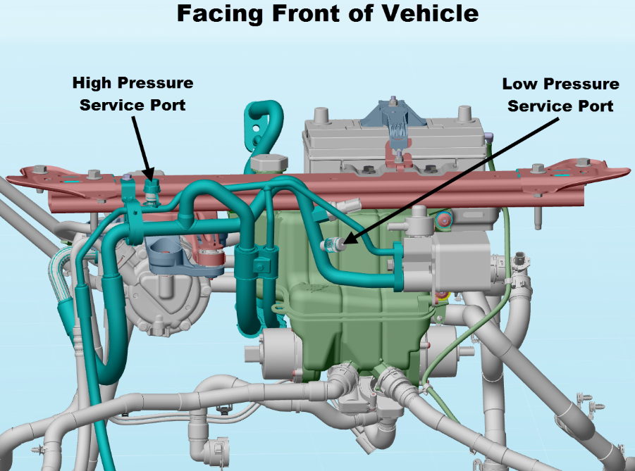
Refrigerant Service Portslink
 |
|---|
The high and low pressure refrigerant service ports are an integral part of the refrigerant lines, and are located under the hood. The high pressure service port is on the line between the condenser outlet and evaporator TXV inlet. The low pressure service port is on the line between the evaporator TXV outlet and the compressor inlet.
Schrader valves in the service ports on the refrigerant lines provide connection points for equipment used to charge / evacuate the system for servicing purposes. The connections are standard couplers for R134a or R1234yf refrigerant. Each refrigerant type requires a unique port size and associated coupler. Both service ports are fitted with a screw-on cap to prevent refrigerant from leaking through the valves and to prevent dirt from entering the service port.
Warning
Servicing must only be carried out by personnel familiar with both the vehicle system and the charging and testing equipment. All operations must be carried out in a well-ventilated area away from open flame and heat sources. R1234yf and R134a are considered hazardous liquids and can cause serious injury if handled incorrectly.
Suitable protective clothing, consisting of face and eye protection, heat-proof gloves, rubber boots, and apron or waterproof overalls must be worn when carrying out operations on the air conditioning system.
Caution
Keep the charge ports capped at all times to prevent contamination.
Note
Always locate and repair the source of a refrigerant leak before recharging the system. tom of the valve housing. The spring ensures that all liquid refrigerant vaporizes before exiting the evaporator.