Rear Doors (Falcon doors)link
Last updated: September 18, 2024
Overviewlink
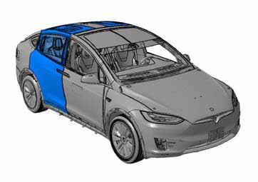
The 2021+ Model X second row passenger door has a unique style that can articulate on two axes of movement to allow the greatest level of ingress and egress. Each rear door consists of an upper and lower section whose movement is each powered by two electromechanical struts, meaning that there are four struts per door and a total of eight struts per vehicle.
 |
|---|
| Rear doors when closed - front view |
 |
|---|
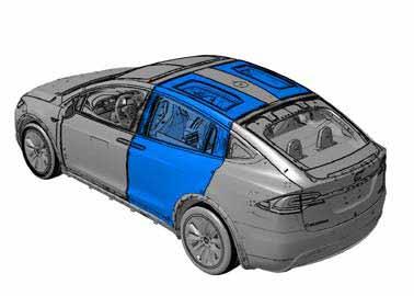
| Rear doors when closed - rear view |
Besides the ultrasonic sensor controller, the two doors are mirror images of each other in terms of parts and operation. This document uses the left hand (LH) door (which includes the ultrasonic sensor controller) for all examples. The right hand (RH) side behaves the same.
 |
|---|
| Rear doors when closed - bottom view |
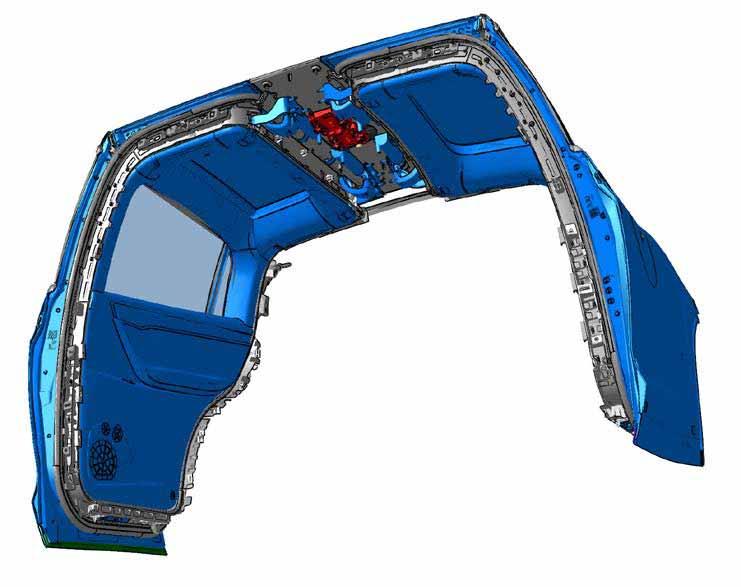
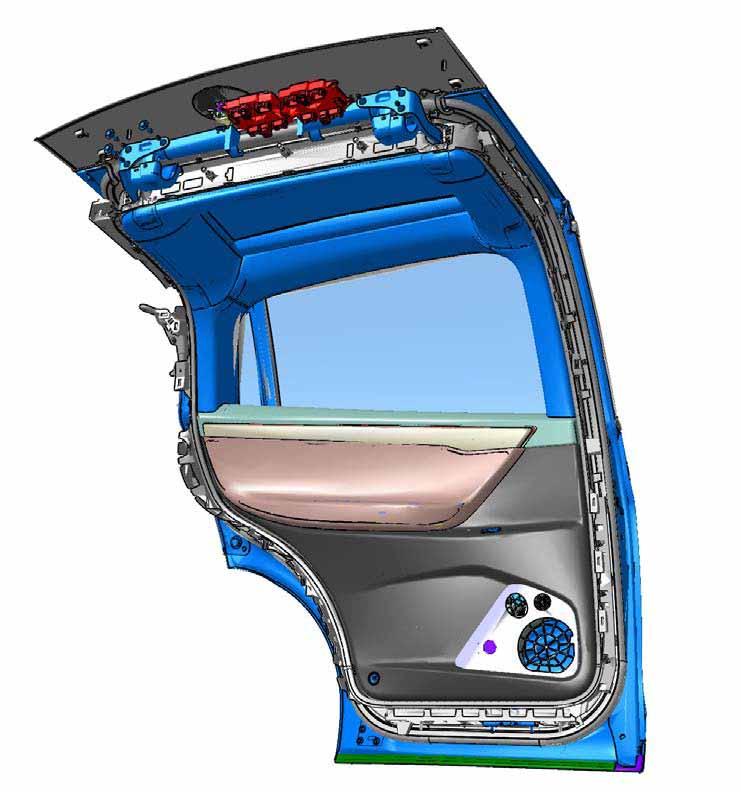
The figure below shows the entire LH rear door as seen from inside the vehicle. The trim pieces shown cover all joints and mask the operation of the door. Most pinch zones are removed, leaving a sleek and stylish door design.
 |
|---|
| LH rear door - interior view |
Componentslink
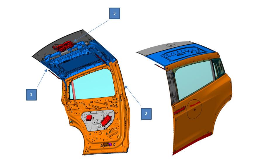
The main functional portions of the doors can be separated into two major sections as shown below. The upper door moves independently of the lower door, and extra electrical hardware is used for sensing and control. Other minor components are mentioned at the end of this section.
 |
|---|
| 1. Upper (primary) door 2. Lower (secondary) door 3. Electrical hardware |
Upper Doorlink
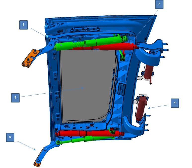
The upper door attaches to the body of 2021+ Model X at the center spine via hinges. Inside the spine are two large springs for each door (four springs in total). Each upper door is driven by two electromechanical struts, one mounted in the front and one in the rear. Each upper door strut is attached to the center spine and to the upper door, providing movement for the upper door. The upper doors have a fixed glass panel which becomes the roof when the door is closed. The upper door glass is not movable and is attached to the upper door structure.
 |
|---|
| 1. Lower secondary door struts (green) 2. Upper primary door struts (red) 3. Upper fixed glass 4. Springs 5. Attachment point to lower door |
Power Strutslink
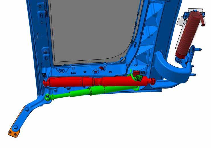
The power struts are very similar to the liftgate struts. Each strut can extend and retract. When extended, they push out and pivot the corresponding body piece around a fixed hinge. The upper door is hinged near the spring against the body spine. The lower door is hinged from the upper door.
The electromechanical struts are controlled and powered by the rear door electromechanical controllers. Each strut receives its electrical power from its respective rear door electromechanical controller. There are a total of four struts in each door. Two primary struts (front and rear) attach to the roof of 2021+ Model X and to the upper door, to move the upper portion of the door. The two secondary struts (front and rear) attach to the upper door and the lower door, to move the lower portion of the door.
Each strut includes an electrical motor, which turns a threaded internal screw against a stationary internally threaded nut to achieve movement. Two hall-effect sensors per strut act as a relative encoder and allow the controller to control the door's position and speed.
Note
Relative encoders lose their ability to report position when 12V power is lost. Therefore, whenever the rear door electromechanical controllers lose power or the struts are disconnected from the module, a calibration procedure must be performed via the vehicle touchscreen or via the B-pillar switch in order to reset to a known position. See Door calibration section for more information.
 |
|---|
| Rear door struts |
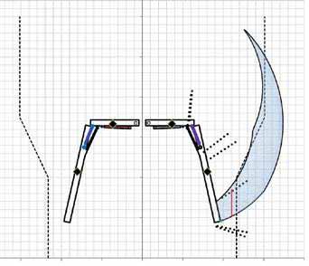
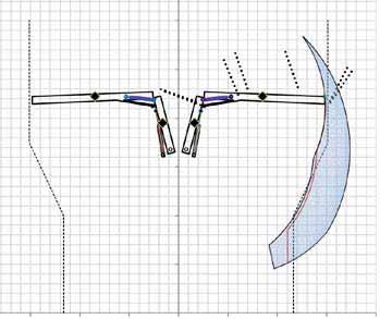
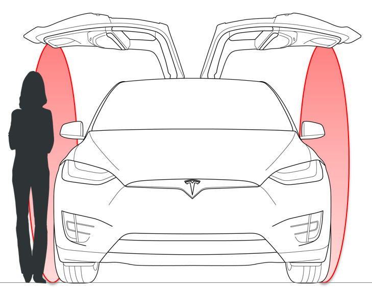
The independent operation of any of the struts allows for a wide range of possibilities for opening and closing profiles. The area of possible openings is shown below. The end tip of the door can be anywhere within the blue area.
 |
|---|
| Doors in closed position |
These opening and closing profiles are subject to change in the firmware. In general, two profiles are most commonly used:
- The most narrow profile, or left side of the blue area, is used whenever the controls want the most conservative opening to avoid contact. The upper door opens first while the lower door remains almost vertical. After the upper door fully opens, the lower door opens as much as the free space next to the vehicle allows.
- The most wide profile, or right side of the blue area, is used whenever the controls want the fastest opening. Both the upper and lower door open at the same time. This is only possible when there is enough space next to the vehicle.
 |
|---|
| Doors in almost fully open position following the most narrow opening profile (left side of the blue area) |
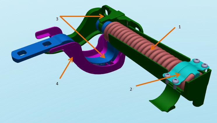
Springslink
Four torsion springs (two per door, shown below) are installed into the center spine of the vehicle near the hinges for the upper doors. The torsion springs provide assistance or resistance during movement of the door, depending on their location. This provides torque to help open the door.
 |
|---|
| 1. Spring 2. Spring hold-down bracket 3. Hinge 4. Hinge cover |
Each door has two springs, one in the front and one in the rear. The springs are installed while the upper door is fully open without the strut installed. In this position, the springs can be dropped into place and are not tensioned. They are held in place with a bracket.
Warning
- When working on and around the springs, take caution to prevent injury. The springs are under a significant load when the upper door is in its closed position.
- If the lower door and/or the struts are removed, be careful of the movement of the door due to the spring force.
- Ensure that the opposite rear door is closed before removing a rear door strut. The spring provides very little resistance when the upper door is fully open.
- When the struts are disconnected and the upper door is under spring tension, the door can over-extend and might contact the opposite upper door if it is open.
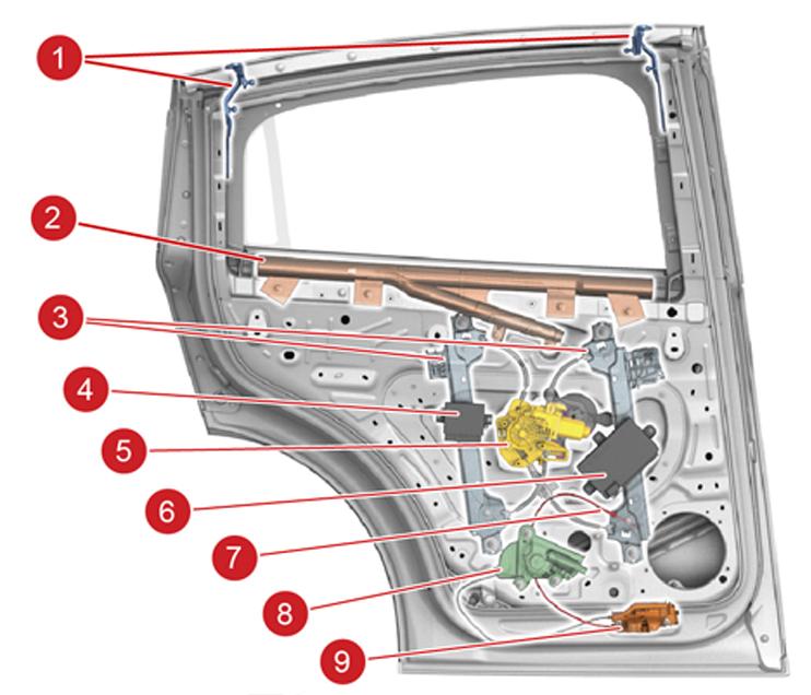
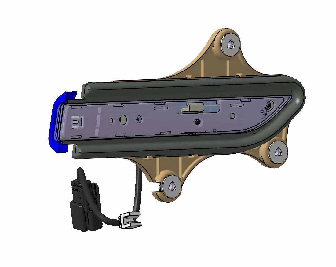
Lower Doorlink
While the actuators for the rear doors are mostly located in the upper door, most of the electronic components are located in the lower door.
 |
|---|
| 1. Attachment point from upper door 2. Airbag 3. Window track 4. Ultrasonic electronic control unit (ECU) 5. Window motor 6. Rear door controller 7. Manual pull cable to release latch and open door 8. Latch motor 9. Latch |
 |
|---|
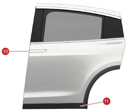
| 10. External door handle 11. Rear door cladding assembly |
Door Handlelink
The door handles on the rear doors operate the same as the front door handles. When the plastic bezel is pressed, the internal switch is engaged. Specific door handle information can be found in the Powered Front Doors Theory of Operation section.
 |
|---|
| Rear door handle - interior view |
Airbaglink
An airbag is located under the trim on the bottom sill of the window which operates in crash scenarios. For specific safety system operations, refer to the section in the Theory of Operation
Door Latchlink
The latch on the rear door is a cinching latch. This means that the door will be pulled closed by cinching motor.
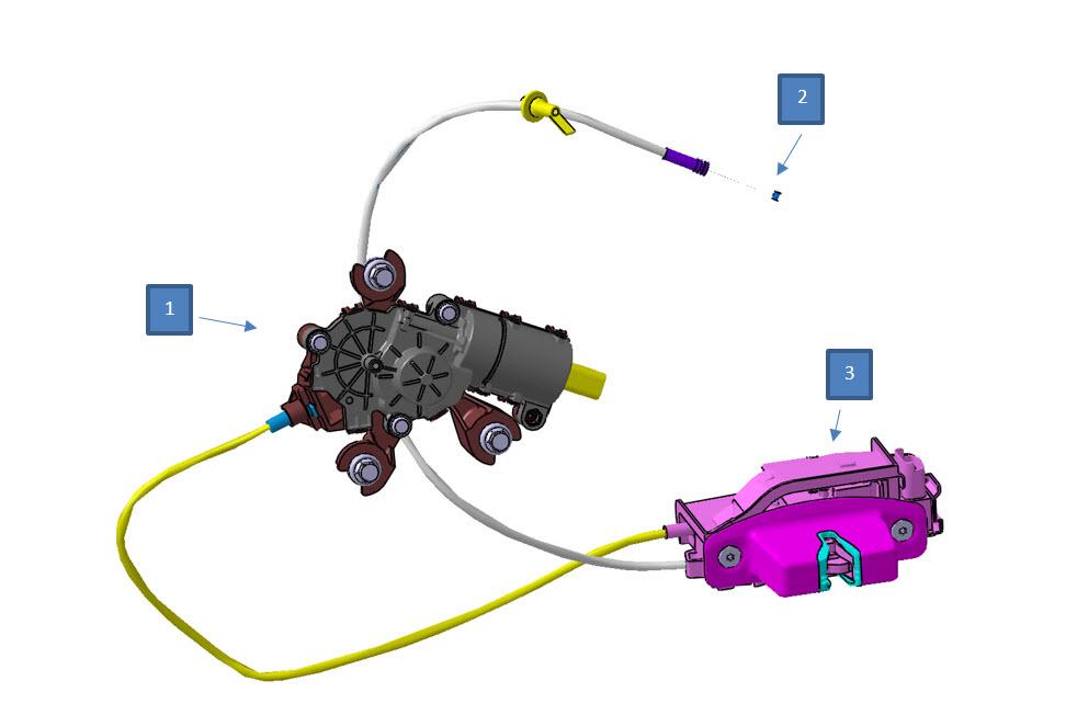 |
|---|
| 1. Latch motor 2. Manual pull cable latch release 3. Latch mechanism |
There is a single latch for each rear door, which connects with a striker on the bottom of the door sill. The striker and latch have minor adjustment capabilities with their mounting bolts for proper alignment of the doors and body.
The manual pull cable is routed behind the speaker on the door. The latch state and commands are determined via the rear door controller for that particular door.
Controllers and Sensorslink
In order to control the rear doors and to process the signals from the various sensors in the rear doors, 2021+ Model X uses multiple controllers. The below figure shows the location of the controllers and sensors in both the upper and the lower door. This section will describe the different controllers that are necessary to control the rear doors and to avoid obstacles.
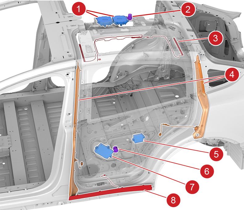 |
|---|
| 1. Rear door electromechanical controllers (1 per door, 2 total) 2. Spine ultrasonic sensor (1 total) 3. Falcon door inductive pinch sensor (Note: inductive pinch sensor is not present on 2021+ Model X) 4. Lower door pinch strips (2 per door, 4 total) 5. Ultrasonic ECU (1 total, in LH door) 6. Door ultrasonic sensor (1 per door, 2 total) 7. Rear door controller (1 per door, 2 total) 8. Rear door cladding assembly with capacitive sensor (1 per door, 2 total) (Note: capacitive sensor is not present on 2021+ Model X) |
Body Controller Falcon Driver / Passenger (BCFALCD / BCFALCP)link
There are two rear door electromechanical controllers, both mounted on the center spine inside the vehicle. The forward module controls the left rear door. The rear module controls the right rear door. Each module receives input on its respective side for switches, relative encoders, and door controllers. Both modules communicate on the sensor controller area network (CAN) bus as well as the body CAN bus. Each module has 12V power input and distributes current to the struts to control opening of its respective upper and lower door. The passenger side module receives a ground input to identify it as being on the passenger side of the vehicle.
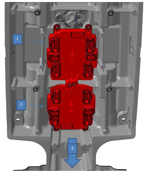 |
|---|
| 1. RH rear door electromechanical controller 2. LH rear door electromechanical controller 3. Front of vehicle |
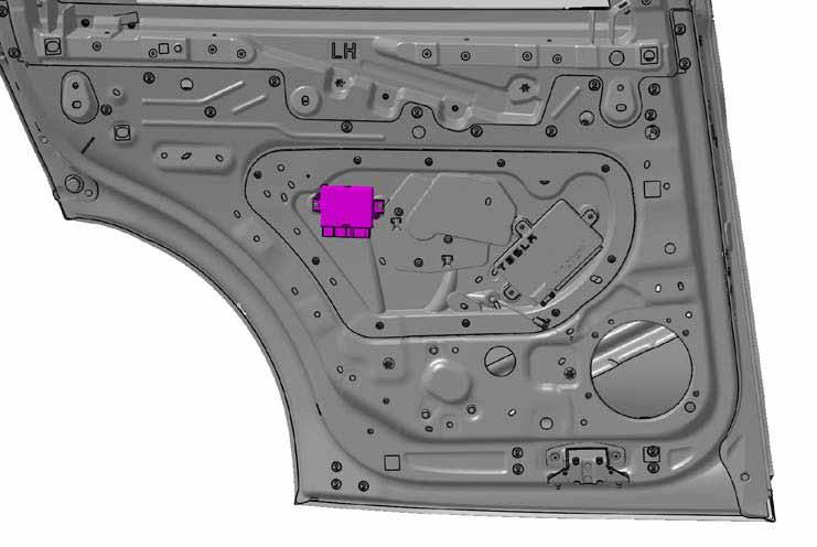
Body Controller Rear Driver / Passenger Module (BCRDM / BCRPM)link
Each door has its own door controller. The primary function of this controller is to communicate with and control the windows, door handles, switches, and latch operations. It outputs on CAN via the body bus. Housed internally to the controller is an inertia measurement unit (IMU), which works as an accelerometer for bump detection. This part is integrated into the printed circuit board (PCB) of the body controller and is replaced as a unit. More information can be found in the Reactive sensors section of this document.
 |
|---|
| Body Controller Rear Module location |
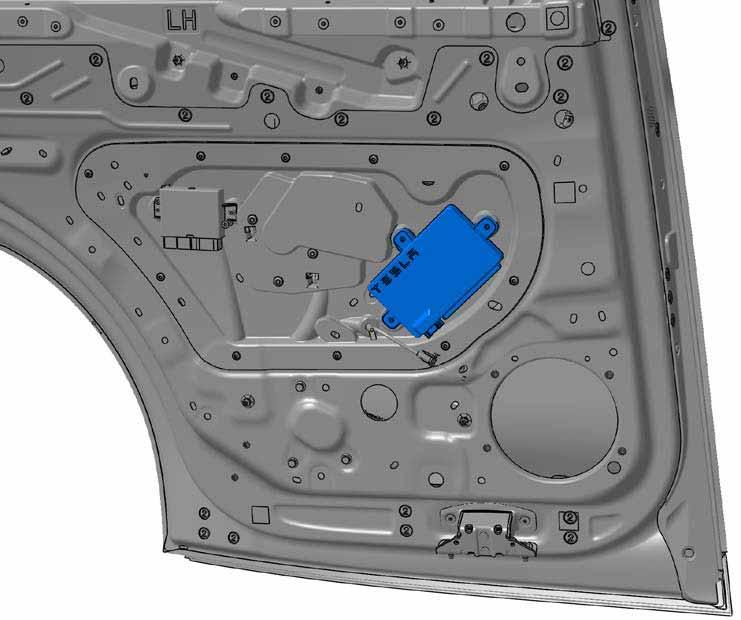
Ultrasonic Sensor ECU (SNSUS)link
2021+ Model X has one ultrasonic electronic control unit (ECU), which has dedicated control and communication with the five ultrasonic sensors which monitor the rear door surroundings.
This ECU is mounted in the left hand (LH) door and receives data from the five ultrasonic sensors installed in the two rear doors and the center spine. This data is then output to a dedicated sensor CAN bus to the rear door Falcon door controllers (BCFALCD / BCFALDP).
 |
|---|
| Ultrasonic Sensor ECU location |
Ultrasonic Sensorslink
The ultrasonic sensors provide proactive sensing for the rear doors by preventing them from colliding with adjacent vehicles or objects, ceilings, low-hanging objects above the vehicle, or closing onto a person or object.
The ultrasonic sensors work nearly identically to park assist sensors in the front and rear fascias. Each sensor emits a high frequency signal in the ultrasonic spectrum, and calculates distance based on the time it takes for the signal to bounce back on an obstacle.
2021+ Model X uses five ultrasonic sensors to continuously scan surroundings of the rear doors:
- Spine (roof)
- Left-hand (LH) door outward
- LH door inward
- Right-hand (RH) door outward
- RH door inward
Spine (Roof) Ultrasonic Sensorlink
The spine ultrasonic sensor measures the distance towards the ceiling or any overhead objects.
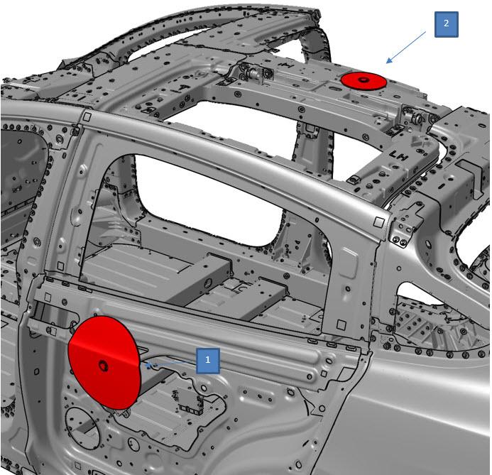 |
|---|
| 1. Lower door ultrasonic sensor (1 each door, 2 total) 2. Upper spine ultrasonic sensor (1 total) |
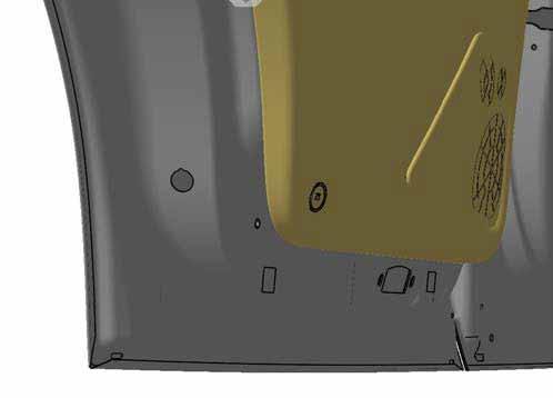
Door Outward Ultrasonic Sensorslink
The outward ultrasonic sensors in each of the rear doors measures the distance from any object to the left and right of the vehicle.
The lower door sensors are mounted differently than the upper (spine) sensor. Each lower door sensor is glued onto the inner side of the outer door panel with an adhesive patch. In addition, the sensor is supported by a tripod style sensor holder which is also glued to the inner side of the outer door panel with adhesive patches. This way, the sensor is not visible from outside the vehicle.
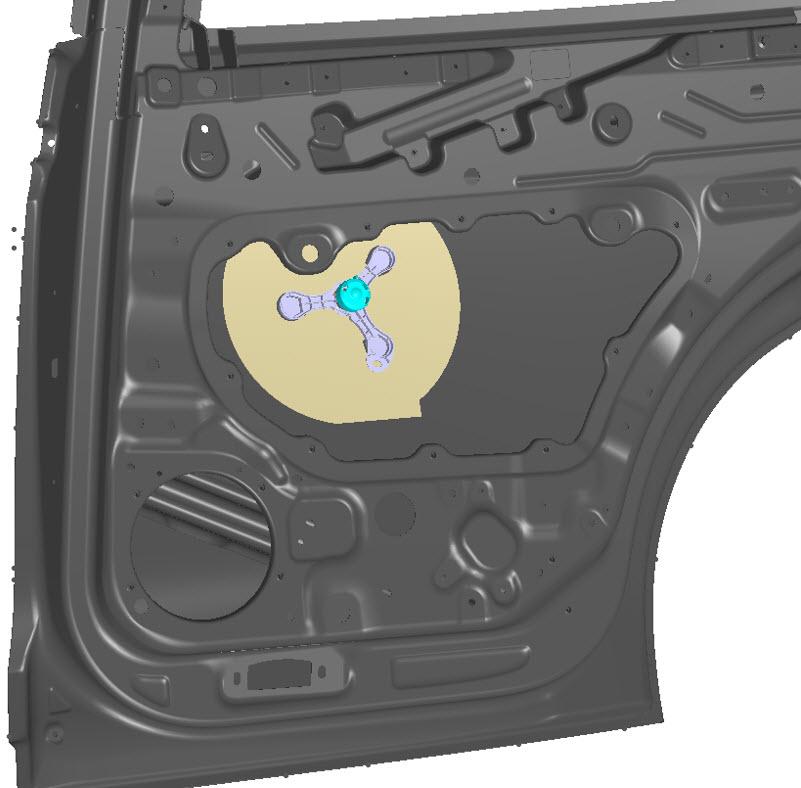 |
|---|
| Outward Ultrasonic Sensor location |
Door Inward Ultrasonic Sensorslink
The inward-facing ultrasonic sensors are located behind the speaker grill and are meant to protect an open rear door from closing onto a person or object.
 |
|---|
| Inward Ultrasonic Sensor location |
Pinch stripslink
Pinch strip sensors can provide reliable obstacle detection, but only once the object is in contact with the pinch strip. This can reduce damage due to contact with an object, but cannot prevent contact since something must be already physically touching the sensor in order for a signal to be sent.
Each door contains a front and rear anti-pinch strip on the lower door, to detect an object when closing. The anti-pinch system comprises two wires encased in a rubber seal, running along the front and rear edges of the lower door. If any obstacle contacts the front or rear edge while the door is closing, the pressure against the two wires inside the seal causes the wires to make contact. This closes an electrical circuit and sends a signal to the corresponding falcon controller, which commands the rear door to stop movement and in some cases to reverse direction a small amount. Specific behavior upon detection is covered in the "Monitoring and Intervention" section of this document. The stronger an object would be pinched by the door, the lower the resistance would be as the contact surface between the two copper wires would be higher, allowing for a higher current to flow.
Ultrasonic Sensor Operationlink
The ultrasonic sensors in the rear door are almost identical to the park assist sensors found on the fascia. The main difference is that they are glued onto the outer door skin, whereas a traditional park assist sensor is not in contact with any body panels. This configuration therefore requires a slightly different detection algorithm.
The steps below explain the high level detection method of 2021+ Model X ultrasonic sensors in the rear doors.
- Sensor sends a series of ultrasonic pulses into the door through the adhesive patch.
- The entire door panel and sensor begin vibrating together at ultrasonic frequencies.
- The entire door panel acts as the sensor surface.
- The sensor drives the system at what is called the resonant period, which is monitored by other electronics and adjusted for maximum efficiency.
- Pulses from the sensor stop after 300ms.
- Energy dissipates from the door panel and the vibration slows.
- Reverb Time is the amount of time it takes for the door and sensor system to come to a stop after starting the pulse.
- Reverb time dictates the minimum distance that can be measured by the sensor that is the point it starts listening for return pulses.
- Sensor listens for return pulse of sound at the resonance period bouncing off an object and returning to entire door surface.
- Timing and strength of the return signal determines distance and magnitude measurements.
- Reflection signal strength (magnitude) returned depends on multiple variable including the density of the material, temperature, and angle to the object.
Note
The resonant period indicates the physical properties (stiffness and damping) of the door and sensor system and changes in this value can indicate problems with the sensor, adhesive coupling, or door panel.
Multiple damping mechanisms like foam pads and butyl patches surround the sensor to reduce signal noise caused by vibrations in the door metal. Specific stiffness and damping are critical to proper operation of the sensor. It is particularly critical that the sensor is correctly adhered to the door skin for the detection to work through the door. The sensor constantly measures fundamental properties that can indicate issues. The sensor holders include a spring to help hold the sensor against the door skin that must be installed properly to maintain adhesion over the life of the vehicle. Always follow the latest installation and repair procedures when working on the ultrasonic sensor.
Specifications:
- Resolution distance measurement: < 2 cm
- Minimum measureable distance: < 30 cm
- Maximum measureable distance: 255 cm
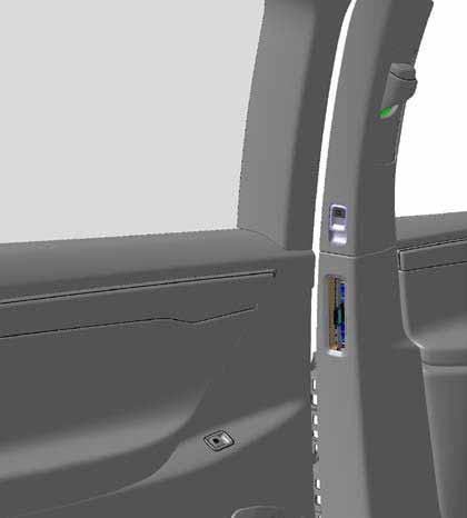
Control Switcheslink
There are two switches for the rear door: the B-pillar switch and the door-mounted (shut face) switch. The B-pillar switch can be pressed in different directions for opening and closing, similar to a power window switch. The door-mounted switch is located on the circular red light on the rearward edge of the door trim when the door is open; that switch is only a single press option.
 |
|---|
| B-pillar switch location |
 |
|---|
| Door-mounted switch location |
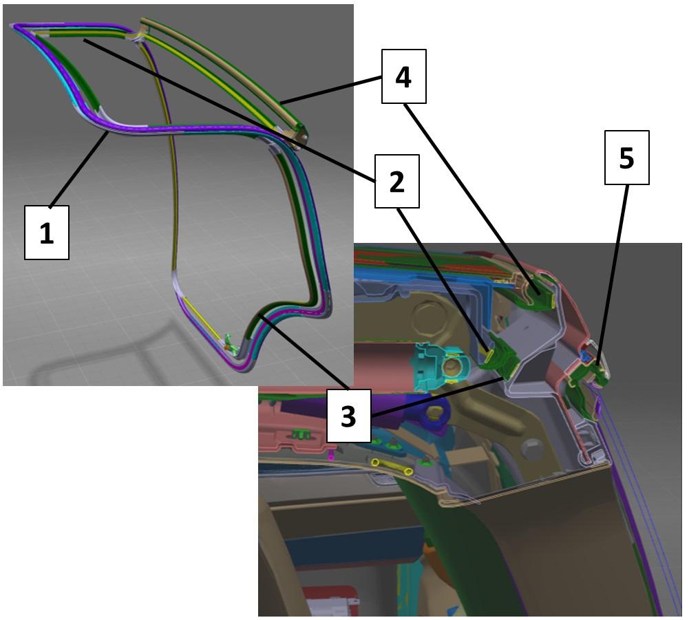
Sealslink
There are several seals on the rear doors.
- Primary seal: Encompasses the entire opening and is primarily to seal out water when the door is closed.
- Upper and lower noise, vibration, and harshness (NVH) seal: Reduce NVH through each respective opening when the door is closed and help to prevent water ingress.
- Upper whisker seal: Prevents debris and water from getting between the upper and lower door when the door is closed. The whisker seal is the first stage of water ingress prevention. It is intended to prevent water from going past the upper/lower door interface.
 |
|---|
| 1. Primary seal 2. Upper NVH seal 3. Lower NVH seal 4. Upper cantrail seal 5. Bright window seal |
The upper cantrail seal pushes water away when the door opens and keeps the gap between upper and lower door dry. Proper seal positioning is critical to achieving overall system performance for the rear door.
Note
Not shown are standard belt seals and moving glass seals for sealing the moving glass inside the lower door. These are fairly standard and behave similar to other vehicles, such as the Model S.
Electrical Diagramslink
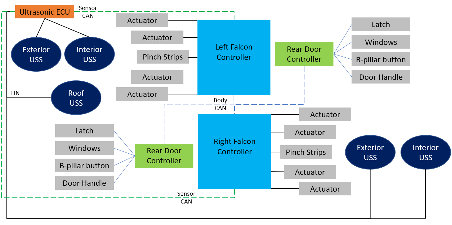
The electrical layout below outlines the key component's tasks and communication paths between the various electronic control units (ECUs) for control of the rear doors.
 |
|---|
The Falcon door controllers provide the main power to the struts and are the overall most critical component for reading information. Two controller area network (CAN) buses are used for the controls. A sensor CAN bus is used only for high speed communication between the Ultrasonic ECU, the Falcon controllers, and the VCLEFT / VCRIGHT controllers. The Falcon controllers need this information to know exactly when to stop and start the struts and therefore control the door position.
Further wiring details can be found in the circuit diagram, available on the service website.
Rear Door Electromechanical Controllerslink
 |
|---|
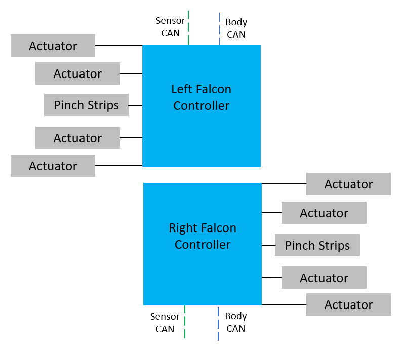
The rear door electromechanical controller distributes power to the eight struts to move the door. Various wires are used for sending power as well as reading the encoder of each strut to determine position. Two main CAN connections are also made for high speed communications to other sensors and modules.
Sensor CAN Buslink
 |
|---|
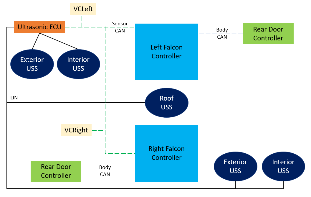
The ultrasonic ECU communicates with each of the five ultrasonic sensors on a local interconnect network (LIN) bus. The raw data from those is filtered down and analyzed in the ultrasonic ECU before transmitting only distance measurement data to the sensor CAN bus.
Door Functionslink
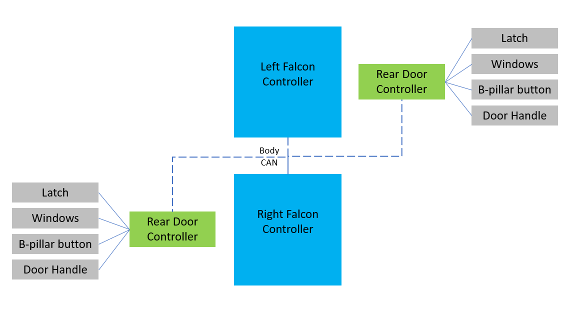
The rear door controllers perform vital functions for each rear door, transmitting messages to the rear door electromechanical controllers via the body CAN bus. The windows, latches, B-pillar switch, door-mounted switch, door handles, and latch communicate via analog inputs to the rear door controllers. Requests for "open", "close", and more are transmitted via CAN to the rear door electromechanical controllers. Latch cinching and opening is controlled by the rear door electromechanical controllers.
 |
|---|
Operationlink
All control-related aspects of the door are subject to change at any time due to firmware revisions; therefore, never assume that the door will behave a certain way.
Openinglink
The opening process of the door can be separated into four stages. This assumes that the door is starting in the fully closed and latched position. Behaviors may be slightly different in other conditions.
User Interactionlink
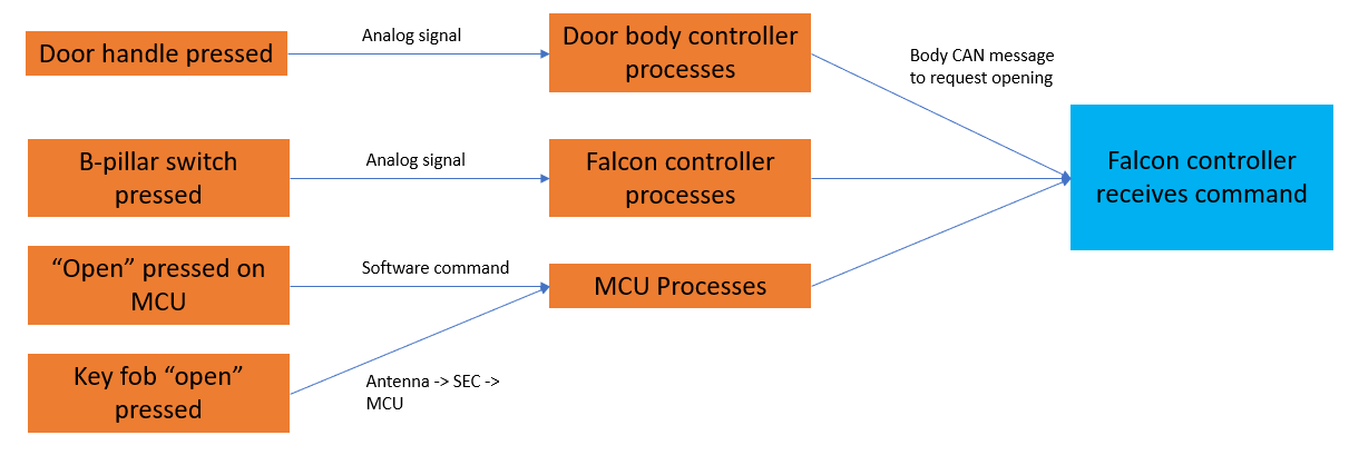
The user can command the rear door to open in multiple ways:
- Press the exterior door handle.
- Pull the interior switch on the B-pillar.
- Touch the "door open" button on the touchscreen.
- Press the rear door button on the key.
Each of these actuations is processed by a controller to recognize the request. The corresponding controller area network (CAN) message is then sent on the body CAN bus. Once the message is sent on CAN, the next stage of opening begins.
 |
|---|
Prerequisites and Initial Conditionslink
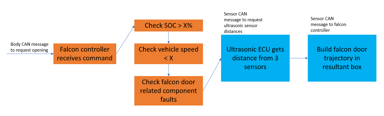
Once the door controller receives the request and knows that the door should be opened, it does a large amount of initial computing to check that it is safe to open the door and determine how the door should be opened. For the former, many different inputs are used to ensure that conditions are stable and safe for opening.
Once the controller determines that the door is safe to open, the rear door electromechanical controller requests the coordinates from the ultrasonic electronic control unit (ECU) for an immediate map of the surroundings of the vehicle. Once the ultrasonic ECU receives the request, the door and spine ultrasonic sensors build an initial map (box) of space within the surroundings. The two dimensions are sent via the sensor CAN bus to the rear door electromechanical controller, where the initial opening trajectory of the door is calculated to fit within that box.
 |
|---|
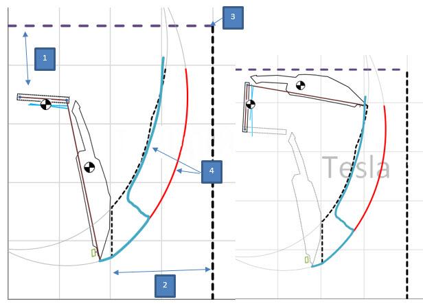 |
|---|
| 1. Initial Y distance obtained from spine ultrasonic sensor 2. Initial X distance obtained from door ultrasonic sensor 3. Imaginary box drawn in software to determine limits of travel 4. Sample trajectories shown of the door's edge in various scenarios to fit inside the box |
If the box is too small, the door maps a trajectory to open to the maximum position possible, then stops to avoid collision. All calculations are done before any movement of the door occurs. Once one rear door has opened, the spine ultrasonic sensor cannot be used to get an accurate ceiling height due to interference; therefore, if the other door is opened, the rear door electromechanical controller uses the last stored value for environmental height.
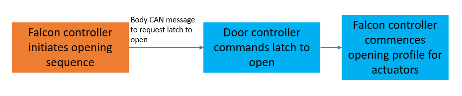
Actuation and Movementlink
The actual operation and movement of the door is fairly straightforward. After the path has been established, and assuming no changes occur, opening begins by unlatching the door. The path in degrees for primary and secondary door angles is mapped. The struts are controlled by % duty cycle to match this path.
 |
|---|
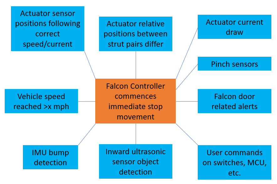
Monitoring and Interventionlink
The most critical part of the control scheme is to be as safe as possible. The modules monitor many sensors to ensure that the opening is occurring as planned. The diagram below indicates the various conditions being monitored and the behaviors that result when certain conditions are triggered.
 |
|---|
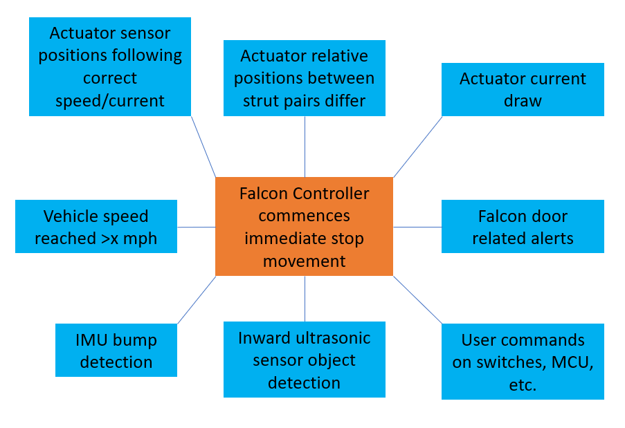
As seen above, conditions are constantly being analyzed during movement and any of them could cause the door to stop movement or alter its path. Ultrasonic sensors can detect objects without physical contact during opening and stop the door before contact occurs. In the special case of ultrasonic sensors seeing an object, the trajectory also changes in real time to account for the new environment. This may be useful in some cases to avoid a low object on the side like a box. The inertia measurement unit (IMU) in the door controller can also detect bumps via an acceleration change. Nearly all of these cases can also be manually overridden by holding the B-pillar button, which overrides the obstacle detections and drives the struts in the most narrow possible path. If the motion was paused for some reason, another user request will continue the motion to open the door.
Closinglink
The closing operation of the door follows the same structure and many of the same guidelines as opening. The information in the following sections are valid for any opening height.
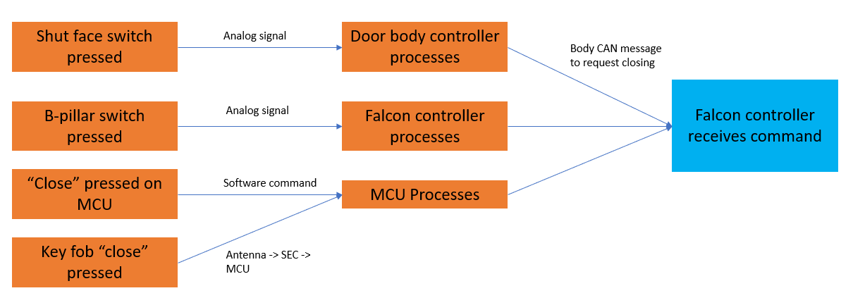
User Interactionlink
The user can command the rear door to open in multiple ways:
- Press the exterior door handle.
- Pull the interior switch on the B-pillar.
- Touch the "door close" button on the touchscreen.
- Touch the "close all" button on the touchscreen.
- Press the rear door button on the key.
- Press the top button on the key to close all closures.
Each of these actuations is processed by a controller to recognize the request. The corresponding CAN message is then sent on the body CAN bus.
 |
|---|
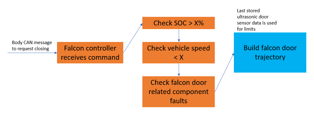
Prerequisites and Initial Conditionslink
Similar conditions also apply for the rear doors to close. However, ultrasonic sensor data is not needed and the last stored position data for the environment is used to determine the closing profile.
 |
|---|
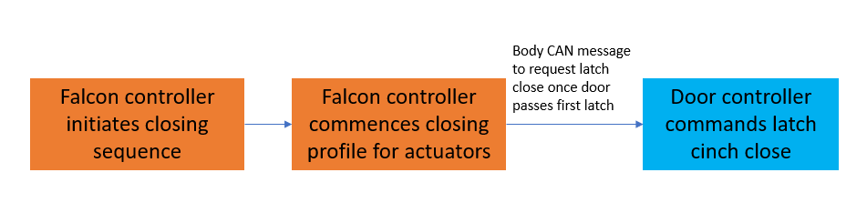
Actuation and Movementlink
The closing movement is identical to the opening, with the latch cinching and closing as the last step.
 |
|---|
Monitoring and Interventionlink
The closing path is the highest priority concern, since that is when pinch is most likely. The door needs to be used with discretion as mostly reactive sensors are available on closing. The sensors that will stop movement are:
- Current sensing in the struts
- Inertia measurement unit (IMU) in the lower door controller
- Inward facing ultrasonic sensor
The rear door does not take into account the position of the front door. The rear doors operate independently of the front doors because there is no interference zone or chance of contact between the front door and rear door regardless of the positions of the doors.
 |
|---|
Door Calibrationlink
The power struts used in 2021+ Model X rear doors use a relative encoder for feedback control, which can only detect movement of the door and not absolute position along its travel. In order to drive the door safely, the electromechanical controller must store a zero position in its memory and count position change from that point. The zero point for the strut is defined as the closed and fully latched position of the door. The door will automatically update the zero point calibration after every latch closed to account for encoder drift and missed counts in normal operation. The door should never need manual calibration in everyday use, but there are some service situations where the door may need to be manually calibrated. The touchscreen and a vehicle alert will indicate any time the ECU needs to recalibrate:
Situations such as:
- 12V power loss or component replacement of the rear door electromechanical controller always requires recalibration.
- In these cases, the memory of the zero position may be out of date since the controller would not have been able to count encoder movement when powered off.
- The latch is closed with the door reading a position far outside of the last latch position.
- The previous zero position is erased and when unlatched, the door will need to be calibrated.
- The two struts on a single door section are mismatched by more than 5 degrees, indicating a possible issue with encoder measurements.
- Calibration will zero both struts to the same point to resume normal door behavior.
- This can occur when a strut is replaced and the positions mismatches due to backlash of the new strut.
- Persistent calibration loss can indicate disconnected struts or missing encoder counts.
When the vehicle recognizes that it needs a calibration on one or both doors, it will show a pop-up on the touchscreen. The user can press-and-hold the "calibrate" button on the pop-up to calibrate the door. The rear door will close slowly until it fully latches. Alternatively, the B-pillar switch can be used to perform the same action.
Warning
The Falcon control unit will override all obstacle detection during the calibration procedure, so preforming the procedure should only be done in a clear area. It is also important not touch the door during calibration, or to latch the latch manually.