Structural High Voltage Battery Software Managementlink
Last updated: December 11, 2024
Overviewlink
The High Voltage (HV) battery is made of thousands of lithium-ion cells to store energy and provide power to the powertrain and the low voltage system.
A battery cell does not have an ON/OFF button; it is always ON when connected to a load. Therefore, the HV battery has embedded hardware to manage and control this power in an efficient and safe way. These devices are controlled by extensive software systems to cover situations involving drive, charge, standby, support, and fault states to mitigate unexpected situations.
The ECUs in the High Voltage Controller (HVC) communicate on the vehicle CAN bus or Etherloop to transmit and receive important signals from the power conversion system (PCS), drive inverters, external charging equipment, pedal monitor, gateway, body controls, etc., to allow proper power limits and vehicle behavior.
Battery Stateslink
The BMS and other Electronic Control Units (ECUs) in the high voltage controller (HVC) control the battery behavior and typically operate in one of 6 states. The Support and Conditioning are combined in the list below. The BMS receives state request information from the vehicle body control system which tells the BMS whether to enable High Voltage (HV) for drive, support, and charge. Charge requires some extra signals from the car computer. The different BMS states listed below are transmitted on CAN under "BMS_state" signal:
- Drive
- Charge
- Support or Conditioning
- Standby
- Fault
Note
All key on/off signals are controlled through CAN, with no hardware signals used in this system's design.
Drivelink
In drive state, HVC allows the powertrain to pull maximum discharge and regenerative/charge power specified for the HV battery according to conditions (cell array temperature, state of charge, brick voltages and more).
For the HVC to transition to drive state, the following conditions must be met:
- Key and driver present
- Pack-contactors - closed
- Proximity is not engaged (no charge equipment connected to the vehicle)
- Enter state - vehicle body controllers requests drive
- Exit state - drive request absent
Chargelink
The Charge state is enabled when vehicle is connected to an external charging and conditions are met for the HV battery to charge. The external charge power can be from one of many AC charging sources, such as a Universal Mobile Connector (UMC) or Wall Connector. This state monitors temperature and voltage to determine end of charge.
The HVC makes the final call on whether the vehicle can charge. The power conversion system (PCS) is subordinate to the HVC. The HVC takes input from the touchscreen (UI), charge port, and vehicle body controllers in determining when it should enter Charge.
To enter the Charge state, the charge port indicates to the HVC that a cable is connected, and charge power is available. Next, the BMS confirms that HV battery is able to charge, UI charge termination target and the vehicle state of charge (SOC) to decide whether it needs to charge. If charging is required and possible, the BMS requests charge to be enabled from the vehicle body controllers. Lastly, vehicle body controllers confirm the UI request for enabling / disabling Charge and the vehicle state. If both are correct, the vehicle body controllers enable Charge.
The BMS enters the Charge state after the charge port ECU and EVSE have agreed on both sides and starts the charging sequence.
Charge and Fast Charge are combined into one state. The different behaviors are handled by the charge state machine. It is a separate substate machine that only runs when the main state machine is in the Charge state. The HVC close fast charge contactors when relevant.
- Pack-contactors - Closed
- Enter state - BMS sends charge request
- Exit state - BMS terminates charge request
Support or Conditioninglink
Conditioning is activated for supporting the low voltage system along with keeping the low voltage battery charged.
This is done through the power conversion system (PCS). During charge and drive states (pack-contactors closed), the PCS charges the low voltage battery. However, the low voltage battery might require support (aka, charging power) at any time (for instance, during a FW update or when vehicle is parked for long period of times)
Hence, the Support state which is specifically intended to charge the low voltage battery when the pack-contactors would normally be open.
Low and mid voltage battery management is handled by the vehicle body controllers and low voltage battery vehicle controller (VCFRONT). The vehicle body controllers will command the HVC to close pack-contactors for support.
- Pack-contactors - closed
- Enter state - vehicle body controllers send Support request while monitoring the low voltage battery
- Exit state- vehicle body controllers terminate the Support signal, or another state such as Drive or Charge is activated
Standbylink
The Standby state is active when the HV battery is not needed but vehicle is not asleep. The pack-contactors open so the HV battery is isolated from the vehicle and no high voltage is present. Most components are powered via the low or mid voltage battery in Standby mode. Only the high voltage controller (HVC) is directly connected to the high voltage and could still operate without the low voltage battery (as seen in the Energy Reserve Supply section, the low voltage battery is needed to power up the HVC and the energy reserve supply).
- Pack-contactors - open
- Enter state - No other state signals are present
- Exit state - Another state signal becomes active
Faultlink
The High Voltage Controller (HVC) ECU can detect a condition with the HV battery internal vitals and act for vehicle safety and HV battery preservation.
If the condition is detected while pack-contactors are closed, the system responds to limit or stop current operation. There are different levels of alerts which lead to different responses from the system:
- Level 1: The condition requires the system to limit power
- The HVC sets a power limit (could be either limitation on voltage or current) for another powertrain component to not exceed.
- Level 2: The condition requires the system to gracefully stop current from flowing and the vehicle receiving power
- The HVC will send an alert requiring all components to stop drawing power.
- The HVC will then open the pack-contactors once the current is low enough
Note
The pack-contactors cannot be opened under load, as this could result in heat dissipation that could damage other components.
- Level 3: The condition requires the system to immediately stop current flow.
- The HVC sends an analog signal to the pyro-disconnect that causes the HV loop to open, even under load.
Once the system is in Fault state, alerts will be broadcast over CAN to let the gateway know what self-detected error is preventing the vehicle from entering other states. The contactors are opened during this state.
- Pack-contactors - open
- Enter state - Fault is detected and active
- Exit state - Fault clearing state for the specific fault clears the fault and allows state change
Power Limits and Predictionslink
The HV battery capability at any given state can be a limiting factor for the performance of the powertrain, when charging or driving. The HVC sets limits and calculates the power available for the powertrain to protect the cells. The HVC sets limits for the cells to not exceed predefined current and voltage limits.
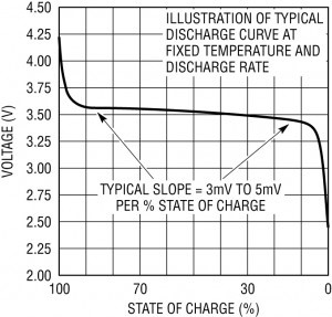
Cell Voltage Limitslink
HV battery cells should operate within 2.5V to 4.2V to avoid irreversible damage. 100% SOC is at 4.2V and 0% SOC is at 2.9V open circuit voltage.
As seen below, the voltage of the cell is stable for most of the SOC band. There is a first sharp voltage decrease from 4.2V to 3.7V (nominal voltage) and then the voltage stays stable to low SOC.
 |
|---|
| Voltage vs. SOC for lithium ion chemistries |
The cells have an internal impedance, or resistance. That resistance causes the voltage across the cell to sag when pulling current from the cell and to increase when pushing current to the cell. The higher the current, the higher the cell voltage will change.
When close to 0% SOC, the voltage drops down quickly and it could be easy to exceed 2.5V, especially from the cell impedance which decreases cell voltage. This is why the HVC will lower discharge power limits when SOC decreases to avoid overshooting the floor voltage, which would damage the cell permanently.
On the other hand, when charging (or during regen), there is a sharp increase close to 100% SOC to 4.2V, and the HVC has to manage charge power limits to make sure the cell voltage does not exceed 4.2V (accounting for cell impedance which increases voltage when cells are charging).
To manage these limitations at high and low SOC, the HVC multiplies those numbers by the number of bricks and defines a high-side pack voltage limit not to exceed (during regen or charging) and a low-side limit not to drop below (during driving or other pack discharge). The drive inverters and chargers will regulate their power to not exceed the voltage limits set by the HVC.
Note
HV battery is unable to restrict power coming in or going out of the HV battery. Pack-contactors operate in a binary state, either fully open or fully closed, with no partial or intermediate positions. It is up to the powertrain (mostly drive inverters and charger) to regulate their power to respect bus voltage limits set by the HVC.
The HVC will lower the max bus voltage the powertrain when reaching high SOC (to avoid going over) and increase the min bus voltage when at low SOC (to avoid going under).
Note
LiFePO4 chemistry has an even flatter cell voltage versus SOC curve than lithium ion. This causes challenges for power limits and for estimating SOC and Calculated Amp-hour Capacity (CAC).
Current Limitslink
Fixed Current limits: The HVC sets some overall current limits (charge and discharge) to prevent accelerated degradation of the cells. The cells have a small internal resistance: the more current that flows through them, the more they will heat up.
Max discharge current is 1200A.
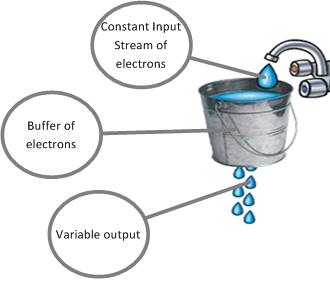
Duration Current limits: The HVC will also limit duration of high discharge currents to protect the system (bus bars, cell interconnects, etc.). This is called the "leaky bucket algorithm". It keeps track of the time when current stays above a certain value and will decrease the current limit after a certain time. It will allow higher current again once the discharge current has been below a threshold for a long enough time.
This algorithm operates like a leaky bucket for electrons continuously receiving a stream of electrons. A constant supply is necessary to keep the bucket filled. If the hole at the bottom (indicating high current) is too large, the bucket empties, requiring a reduction in the hole's size to maintain a proper electron level. The chart below illustrates a section of the algorithm, indicating the reduction in current over time.
 |
|---|
Power Predictionlink
Given all the different limits, the HVC calculates how much power the HV battery will be able to output or take at any given time. The algorithm is complex but considers state of charge (SOC), temperatures, balancing and aging of the bricks, and properties of the charge / discharge of the cells.
The HVC uses the voltage and current limits mentioned above and adds the cell electrochemical characteristics to deduct a max discharge power and min charge power. The following CAN signals are essential to find out what power the HVC was allowing at any given time, as it considers all limits mentioned above:
- BMS_minBusVoltage
- BMS_maxBusVoltage
- BMS_maxChargeCurrent
- BMS_maxRegenPower
- BMS_maxDischargeCurrent
- BMS_maxDischargePower
- BMS_powerLimitsState
Safety Systems to Prevent Cell Damagelink
The HVC will fault and open pack-contactors if the rest of the powertrain does not meet the limits set by the HVC.
The HVC will open contactors if any of the following exceeds the thresholds set by the HVC:
- Temperature
- Cell voltage (high and low)
- Current (charge or discharge)
The HVC sets limits for HV battery protection at the physical limits of the hardware/cells, and adjusts these limits based on nominal operating conditions to ensure safe operation.
For instance, the HVC implements the hardware over-current (HWOC) behavior, where it has a high fixed threshold which immediately triggers the pyro-disconnect. The HVC over-current behavior integrates I^2t spent outside its advertised limits.
Voltage Sense Harness Impedancelink
Cell voltages are key to the proper operation of the powertrain. On the HV battery, the system does not have the ability to measure the voltage of each cell. The system can only measure the voltage of a row of cells connected in parallel, also known as a brick.
Brick voltages are used by the HVC to calculate state of charge (SOC, which is used to calculate vehicle driving range), max discharge current, max charge current, HV battery temperature management, and more. Brick voltages are critical for proper vehicle operation. The HVC will request that charge or discharge stop if the brick voltages are, respectively, too high or too low.
Therefore, it is necessary to make sure that the harness between the bricks and battery monitoring board (BMB, where the voltage is converted into a digital number) is in good shape. To make sure, the HVC can perform a sanity check of individual connections between BMBs and bricks. This test is called a voltage sense harness (VSH) impedance test.
The test is simple. The HVC requests the BMBs to close their bleed field-effect transistors (FETs) across each brick, placing a small resistor across the brick. This creates a small load across the brick. The HVC calculates the voltage difference with and without the bleed resistor. If the voltage drop exceeds 150mV, indicating added resistance on the voltage sense harness (VSH) between the brick and the BMB, the HVC raises a high VSH impedance alert, stopping charge and support. In Drive, an alert for "Car May Not Restart" appears. After the drive, contactors open, making the vehicle unresponsive.
The HVC runs the VSH impedance test on all 110 bricks every 24 hours, or every time the HVC wakes up from sleep if the previous VSH impedance test was not complete.
If the VSH impedance test reveals high impedance, it means inaccurate voltage measurements are possible, so the HVC therefore prevents contactors from closing.
Prechargelink
The drive inverters embed big capacitors. Any capacitor is like a strong magnet for electrons or current. If empty and exposed to a current, it will suck in current at a high rate.
This is why the pack-contactors cannot close directly on the HV bus:
- The capacitors in the drive inverters would suck in huge amounts of current and cause several thousands of amps to rush through the contacts bar for the pack-contactors.
- This would cause arcing, potential failure of the pack-contactors, and damage to the powertrain from the high inrush current.
To avoid this issue, there is a precharge sequence that allows for gradual charging of those capacitors.
There is no precharge relay or resistor. The precharge uses the low-voltage battery and the power conversion system (PCS) to step up the voltage from the low-voltage battery to match the HV battery voltage. The PCS becomes a key component in closing pack-contactors.
- Step 1:
- The HVC sends the request to close pack-contactors to the dedicated processor handling contactor drive power ( high voltage processor (HVP) ).
- The high voltage processor (HVP) powers up the PCS via a dedicated hardware line.
- The high voltage processor (HVP) sends the precharge request to the PCS.
- The high voltage processor (HVP) sends a precharge voltage target to the PCS according to pack voltage (which the high voltage processor (HVP) is sensing directly).
- The high voltage processor (HVP) sends a DCDC PWM enable signal (hardware line) to the PCS.
- Steps 2 and 3:
- The PCS takes the low voltage input power from the low voltage battery and steps it up to the requested voltage sent by the high voltage processor (HVP) . Pack-contactors are still open. This causes the capacitors of the drive unit to charge up and the bus voltage to rise up to match the pack voltage.
- The PCS sends a signal to the high voltage processor (HVP) with the precharge status (FAILED, IDLE, PRECHARGING).
- Step 4:
- Once the high voltage processor (HVP) senses that the DC link voltage is close enough to the pack voltage, it closes the positive pack-contactor.
- Once the positive pack-contactor is closed, the HVC confirms voltage on each side to make sure it is actually closed. It will also confirm the coil current to make sure that enough current was consumed to close the pack-contactor.
- Step 5:
- From there, the HVC closes the negative switch and operates the same check as for the positive one, voltage and coil current.
- Before sending the green light to pull power from the HV battery, the HVC will confirm the common mode between DC link plus to chassis and DC link minus to chassis. If that is within expected range, the HVC will send the HVC the green light to draw power from the HV battery.
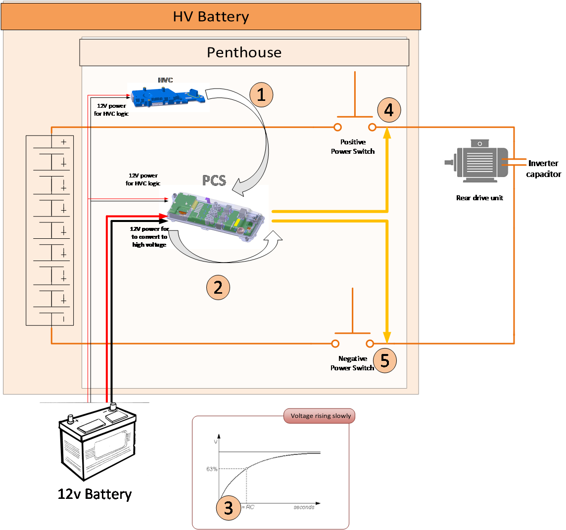 |
|---|
| Precharge sequence |
High Voltage Interlock Looplink
Overview of High Voltage Interlock Looplink
The High Voltage Interlock Loop (HVIL) is a system that ensures all HV connectors are connected before closing contactors. This prevents the HV battery from closing contactors when an HV connector is disconnected, which could expose someone to high voltage.
DC Link voltage is required to be below 60V one second after the HV connector was disconnected. This requirement is met using HVIL to trigger the drive inverters active discharge resistors to reduce the bus voltage when a HV connector is disconnected.
Tesla vehicles can implement two different types of HVIL :
- High Voltage Interlock Loop over Controller Area Network (HVIL over CAN)
- High Voltage Interlock Loop over Low Voltage (HVIL over LV)
This vehicle uses HVIL over LV.
High Voltage Interlock Loop Over Low Voltagelink
HVIL is an electric signal routing through most high voltage (HV) components and HV connectors in the vehicle. The HVC produces a constant 20mA current on the output of the HVIL loop which comes back into the HVC. If the HVC does not detect 20mA, it assumes the HVIL loop is open, suggesting a disconnected or insecurely connected HV connector. Some HV components have a 60ohms resistor between their HVIL input and output, and those components are called HVIL nodes.
High Voltage Interlock Loop Over Controller Area Networklink
HVIL over CAN is based on the same fundamental principles as HVIL over LV. However, certain high-voltage components are not directly connected to the HVIL electrical loop. Instead, these components are designed with the capability to self-detect their HVIL status, specifically whether their high-voltage connector is present. This status information is then transmitted to the high voltage controller via the CAN network.
Operationlink
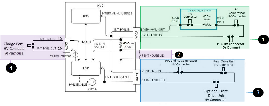
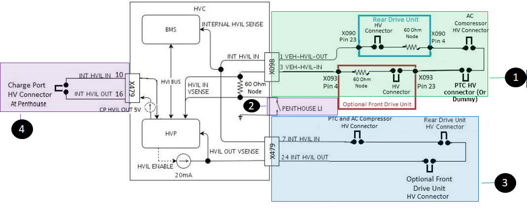
The HVIL system is configured into three sub-loops, each of which is powered by the same current source provided by the High Voltage Controller (HVC). Additionally, a separate loop is dedicated to the charge port, which operates independently of the three main sub-loops.
- HVIL Internal to the Ancillary Bay (referred to as 'Internal loop'): Starts from HVC low voltage connector to FDU connector in the ancillary bay, to the RDU in the ancillary bay, to the cabin heater and compressor connector in the ancillary bay, and back to the HVC low voltage connector.
- HVIL for vehicle powertrain (referred to as 'Vehicle loop'): Starts from HVC, to the HVC vehicle interface connector, to RDU, to compressor, to FDU, and back to the HVC via the vehicle interface connector, to the HVC. There, it will find a 60 ohms resistor before going closing loop to chassis ground via a fastener to the enclosure. That bolt needs to be removed to remove the ancillary bay cover which will open the HVIL loop.
- HVIL for Ancillary Bay Lid (referred to as 'Ancillary bay cover loop'): HVCs with part number revision "-H" and later have an additional input that allows the BMS to know if the HVIL loop is broken at the ancillary bay lid. The BMS measures the voltage across the 60 ohm resistor on the HVIL internally to the HVC. If it reads 1.2V, indicating 20mA flowing through it, the loop preceding that point is fine. However, if the HVIL output voltage stands at 9V (indicating an open state), then the problem likely lies solely with the ancillary bay LID.
- CPIL for charge port connector: Starts from HVC low voltage connector to the charge port connector in the ancillary bay, and back to the HVC low voltage connector.
The HVIL system consists of two loops: one for the internal ancillary bay (drive unit connector and ANC connector) that leads into a vehicle loop which includes all other high-voltage connections and the 2 drive inverter nodes and the charge port loop which is a separate electrical circuit.If the ancillary bay CPIL is broken, it does not affect the state of the vehicle portion of the loop. The chart below provides an overview of the CPIL sub-loops.
 |
|---|
| 1. Vehicle Loop 2. Ancillary Bay lid switch loop 3. Internal (or Ancillary Bay) loop 4. Charge port interlock loop (CPIL) |
| HVIL sub-loops (Battery Perspective) - RWD |
 |
|---|
| 1. Vehicle Loop 2. Ancillary Bay lid switch loop 3. Internal (or Ancillary Bay) loop 4. Charge port interlock loop (CPIL) |
| HVIL sub-loops (Battery Perspective) - AWD |
HVIL for Charge Port Connection to the HV Battery
The HVC has a separate sense circuit to confirm that the charge port is connected to the vehicle at the HV battery. It is called the charge port interlock loop (CPIL).
- If no charge port is connected, the system will allow contactors to close but will prevent fast charge and charge.
- CPIL starts from HVC low voltage connector, goes to the charge port connector in the ancillary bay, and then returns to the HVC low voltage connector.
System Detection Mechanism for HVIL Open
The HVC performs an HVIL check by enabling a 20 mA constant current source and measuring the HVIL input voltage with expected voltage of 20 mA * 60 ohms = 1.2V, with up to ± 10% tolerance.
If the input voltage is not within the expected bounds (see above), the HVC will open contactors if the vehicle is not in an active driving state.
The HVC firmware is able to make distinctions between HVIL failures from the three different loops. To distinguish between HVIL failures, the HVC uses the HVC HVIL input voltage that it receives via the High Voltage Internal (HVI) CAN bus. The HVC HVIL input sense is after the ancillary bay loop and before the vehicle loop. The HVC does not act on the voltage but sends the value over CAN to the HVP. With a healthy HVIL, the HVC should see the same voltage as HVIL output voltage (at the output of the current source) which is 0.02A * (60) Ohms or 1.2V regardless of vehicle configuration.
After the loop exits the HVC and has been around the vehicle loop, the HVC reconnects within itself, linking to a 60ohms resistor before grounding back to the HVC.
The HVC has sources of HVIL faults or indicates the source is unknown:
- Status indicating HVIL ancillary bay internal open circuit fault.: HVIL_STATUS_INTERNAL_OPEN_FAULT
- Status indicating HVIL Vehicle open circuit fault.:
HVIL_STATUS_VEHICLE_OPEN_FAULT
- Unlikely to be present because the loop is shorted
- Status indicating HVIL ancillary bay Lid circuit fault.: HVIL_STATUS_PENTHOUSE_LID_OPEN_FAULT -Unlikely to be present because the ancillary bay lid is shorted on the HVC PCBA board
- Status indicating HVIL number of nodes does not match expected value.: HVIL_STATUS_VEHICLE_NODE_FAULT
- Status indicating HVIL open circuit fault but unable to determine where exactly the fault is.: HVIL_STATUS_UNKNOWN_LOCATION_OPEN_FAULT
1. Ancillary Bay internal open circuit fault:
The ancillary bay HVIL (or internal HVIL) is used to confirm the integrity of the ancillary bay HV circuit. Historically, this loop confirms that the rear drive inverter, front drive inverter, and ancillary HV connectors are present and properly connected to the ancillary bay. If there is a break in internal HVIL, then the internal voltage will be 0V. The internal voltage reading is used to diagnose the ancillary bay HVIL breakage. The HVC measures the Internal HVIL voltage and sends it over CAN to HVC for processing. The internal HVIL voltage measured by the HVC has an expected voltage proportional to the number of HVIL nodes (1.2V for Model S and X (2021+), which have only one HVIL node - inside the HVC). If the internal HVIL voltage is not at the expected level during HVIL check, the HVC reports the HVIL fault as HVIL_STATUS_INTERNAL_.OPEN_FAULT.
2. Vehicle open circuit fault.
Vehicle HVIL fault is detected when one or more external HV components are not connected properly to the HV system. The Vehicle HVIL fault is detected by the HVC when measuring the HVIL output voltage.
- Fault when vehicle loop is open: Vehicle HVIL fault is asserted when HVIL voltage is close to open circuit voltage (9V) with broken vehicle HVIL. In this case, the HVC should report the HVIL status(HVIL_STATUS_VEHICLE) when output HVIL voltage is equal to 9V ± 10% tolerance.
- Fault when missing an HV node: The output HVIL voltage is also used to confirm the correct number of nodes. The output voltage is expected to be at 20 mA * (The number of external Nodes + 1). The +1 is for the added HVC node resistors on the board at the input end. For instance, for 3-node systems, the expected HVIL output voltage is 2.4V.
The Vehicle HVIL open issue is one of the most common HVIL issues in service, as it is the longest loop going through the entire vehicle.
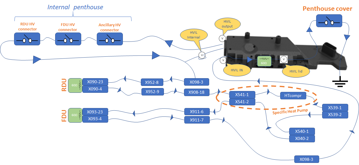
There are two flavors of HVIL vehicle loop: whether the vehicle is RWD, AWD, or equipped with heat pump system versus HV A/C compressor heater.
The HVIL vehicle loop is slightly different for the Model 3 equipped with PTC+HV A/C compressor compared to the Model Y Heat Pump System. The heat pump compressor of the Model Y has a dedicated HV harness from the front of the battery to the compressor. Therefore, there are 2 HV connectors, one at the front of the HV battery and one at the heat pump compressor.
Below, the two HV connectors for the heat pump compressor are labelled X540 (at front of battery) and HTcomp at Heat Pump Compressor.
 |
|---|
| HVIL vehicle loop for Model Y |
Note
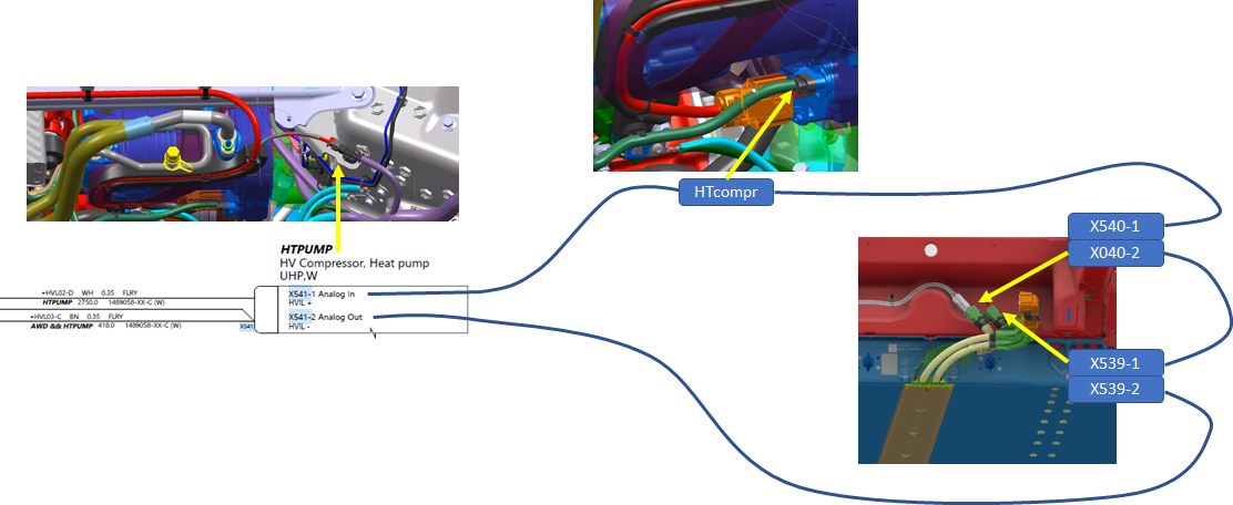
The connector labelled HTcompr, X539, and X540 are not included in the wiring diagram. The part not included in the diagram is represented below. It is the section of harness going from X541 to the Heat Pump Compressor, the front of the HV battery (x540) and the dummy plug on the PTC heater connector (X539).
 |
|---|
| MY HVIL section of harness not represented in wiring diagram |
This setup is different to the Model 3 whom the HV A/C compressor is included with the compressor unit, only one connector labelled X540 situated at the front of the HV battery. See below.
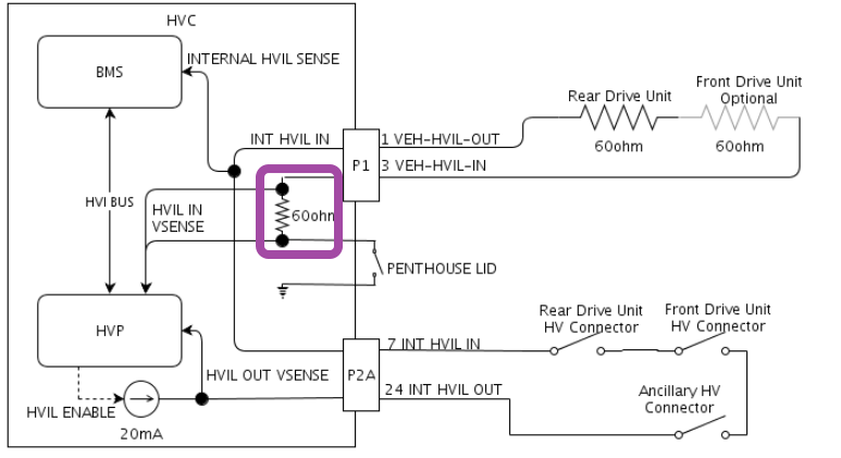
3. Ancillary Bay Lid open circuit fault.
This type of HVIL fault is unlikely on Model S and X (2021+) and is more relevant for Model 3 / Model Y where the ancillary bay cover can be removed without dropping the HV battery.
For Model 3 and Model Y, the ancillary bay cover or lid is equipped with an HVIL sense in order to command contactors to open if someone was to open the ancillary bay cover, because this could expose someone to high voltage.
The HVC is equipped with an HVIL voltage sense when the vehicle open loop comes back into the HVC and across the 60 ohm resistor before the loop goes through the ancillary bay lid.
To sense if the HVIL open is at the ancillary bay lid, the HVC measures the voltage across the resistor. If it measures 1.2Ohm, it means that there is 20mA going through it, meaning that the loop before that point is OK. But if the HVIL output voltage is 9V (meaning opened), then the issue can only be the ancillary bay lid.
 |
|---|
| Ancillary Bay HVIL lid sense |
4. Number of Nodes Does Not Match Expected Value.
This type of HVIL failure will be reported when the HVC measures an output voltage that is lower than the minimum tolerated HVIL output voltage in respect to the number of nodes (number of 60 ohms resistors) in the vehicle.
The output HVIL voltage is also used to confirm the correct number of nodes. The output Voltage is expected to be at 20 mA * [The number of external Nodes + 1] +1 is for the added HVC node resistors on the board on the input end.
For instance, for 2-node systems, the expected HVIL output voltage is 2.4V. If the HVIL output voltage was only 2V, the HVC would report the fault HVIL_STATUS_VEHICLE_NODE_FAULT.
5. Current source failure HVIL current source fault can be detected by measuring all three HVIL voltage senses. If all three voltage senses do not match the expected voltages, then the HVC reports the fault as CURRENT_SOURCE_FAULT.
Diagnostic of the High Voltage Interlock Looplink
See the Service Mode Plus section for more details on the HVIL panels and how they can help with HVIL diagnostic.
High Voltage Isolation from Chassislink
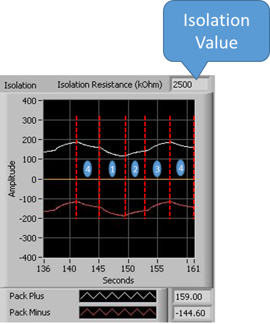
Isolation is the resistance between high voltage (+ or -) and the vehicle frame ground (chassis).
The high voltage electrical system is isolated from the vehicle. This means that there is no (or extremely little) electrical current carrying path between the vehicle and any high voltage conductor. To ensure that this isolation is always met, a monitor is installed in the battery, which periodically measures the resistance between the high voltage conductors and the chassis.
To run the test, the HVC employs two 10 Mohms resistors: one connecting the HV battery enclosure (chassis) to the HV battery positive, and another connecting the HV battery negative to chassis, allowing the high voltage 0V to be close to chassis potential. For example, consider two rubber bands, one attached to each end (HV battery+ and HV battery-) and anchored at the midpoint (0V). When the rubber bands are identical in strength (equal resistance), they keep the 0V position close to the center (chassis).
The HVC also has two resistors of 6 Mohms between chassis and HV battery- and between chassis and HV battery+. The resistors are in series with FET transistors that allow for connecting and disconnecting the resistor from the circuit. The isolation test resistors are located inside of the pack-contactors.
The measurement of isolation from the HVC test has several steps:
- The HVC closes the positive FET transistor and brings the 6 Mohms resistor in parallel to the 10 Mohms resistor between chassis and HV battery+. The resistance is now 3.75 Mohms. The rubber band on that side now has less resistance, and it causes HV battery+ to come closer to the chassis, which pushes HV battery- away from it. The HVC holds this for 4 seconds to give time for HV battery+ and HV battery- to move down.
- The HVC opens the positive FET for 4 seconds, which causes HV battery+ and HV battery- to come back up to a middle level.
- The HVC closes the negative FET transistor and brings the 6 Mohms resistor in parallel to the 10Mohms resistor between chassis and HV battery-. The resistance is now 3.75Mohms. The rubber band on that side is now weaker (less resistance), and it causes HV battery- to come closer to the chassis, which pushes HV battery+ away from it. The HVC holds this for 4 seconds to give time for HV battery+ and HV battery- to move up.
- Then, The HVC opens the negative FET for 4 seconds, which causes HV battery+ and HV battery- to come back up to a middle level.
The HVC measures the voltage on position high and low and deducts the resistance between chassis and the HV battery. The cycle can then start again from step 1.
 |
|---|
In the event of an isolation issue, additional resistance runs parallel to the 10 Mohms and 6 Mohms resistors. The more the isolation degrades, the lower this resistance becomes. That resistance will cause the 10 Mohms and the 6 Mohms resistors to be obsolete, as all the current will pass through the new resistance caused by the isolation degradation. This will cause HV battery+ and HV battery- to not move as expected: the rubber band is weakened, and the HV battery voltage is pulled significantly on the other side. The HVC would detect HV battery voltages at unexpected positions, leading to low isolation readings. If isolation falls below 500 Ohm/Volt or 192 Kohms at 385V, the HVC will report an alert, notifying the customer of a potential issue.
Forced External Isolation Measurementlink
Isolation resistors are before pack-contactors. This means that the system is unable to measure isolation after pack-contactors (or outside the HV battery) if the pack-contactors are opened. If the HVC detects low isolation with pack-contactors closed, and it restores when they're open, the HVC won't know if external isolation is restored when closing pack-contactors again. Therefore, the HVC will need to run a forced external isolation measurement (FEIM) that will allow it to get an isolation measurement without closing pack-contactors.
With a PCS, the DC link voltage can be increased independently using the step-up DCDC, which converts low voltage battery power to high voltage (350+ V). To perform FEIM, the HVC asks the PCS to precharge the bus to pack voltage, and then takes an isolation measurement when the DC link voltage is near pack voltage.
Consequence for vehicle behavior of an isolation alert:
- If the vehicle is in Standby, Support, or Charge mode, the failure is reported as a fault. The vehicle opens contactors or keeps them open. Charge or Support will stop.
- If the vehicle is in Drive, the failure is reported as a warning, but does not open the contactors to prevent a loss of drive. The vehicle will not be able to restart if the isolation problem is still present. If the HVC detects low isolation during a drive, it will raise an internal flag and perform a forced external isolation measurement when closing the contactors again. If isolation is not restored, contactors will not close. As a result, the vehicle will not be drivable, and it could become unresponsive as the low voltage battery degrades.
Conditions that can cause low isolation from high voltage to chassis:
- Physical condition of the insulation material
- Contamination (dust, bolts, etc.)
- Moisture (water ingress, internal coolant leak, etc.)
Battery Capacity and Range Calculationslink
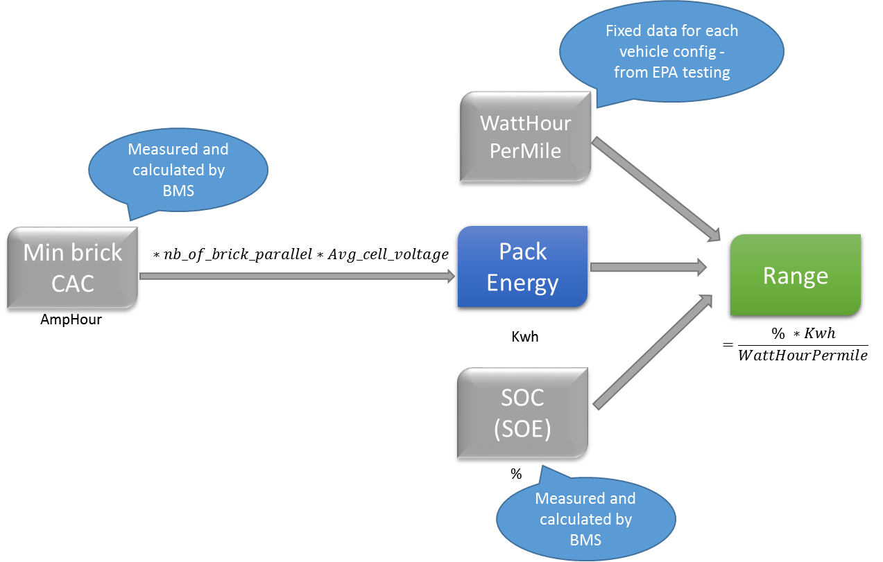
The range of the vehicle, typically displayed in miles or kilometers, is a function of many parameters in the vehicle to provide the most accurate assessment of range remaining. This is to prevent the customer from running out of charge prematurely. The voltage of the HV battery is directly correlated to the state of charge (SOC) of the vehicle. This is indicated by a bar on the touchscreen (UI). However, the capacity of the HV battery changes over time, which means 100% SOC will always be 100% but the range can change based on the battery capacity. The capacity is tracked by the HVC in a value called calculated amp-hour capacity (CAC).
Range Estimationlink
The range calculation can be shown using the flowchart below.
 |
|---|
Starting from left to right, the first important number that comes into the equation is CAC. This number can be viewed in logs and is constantly changing from high voltage battery management system calculations to update the value to reflect energy capabilities in the HV battery.
Note
This value is the Ah capacity for a single brick. All bricks have their capacities calculated, but the minimum brick is used for the range calculation, as it is the brick that will limit the HV battery capacity.
To get the full capacity of the entire battery, the value will need to be multiplied by the average brick voltage to determine the kWh value.
Note
Temperature affects the full HV battery energy, with a cold HV battery having reduced energy capacity compared to a warmer one.
The full HV battery energy is multiplied by the state of charge (SOC) of the HV battery. Therefore 50% SOC means .5 (or half) of the full HV battery energy.
The energy is then divided by a fixed watt-hour per mile value, which is pre-programmed into the HV battery based on the vehicle's rated range and configuration settings. This is the average efficiency found during EPA drive cycle testing (or equivalent regional standard). The final number will appear in units of distance, and this is what is displayed on the touchscreen.
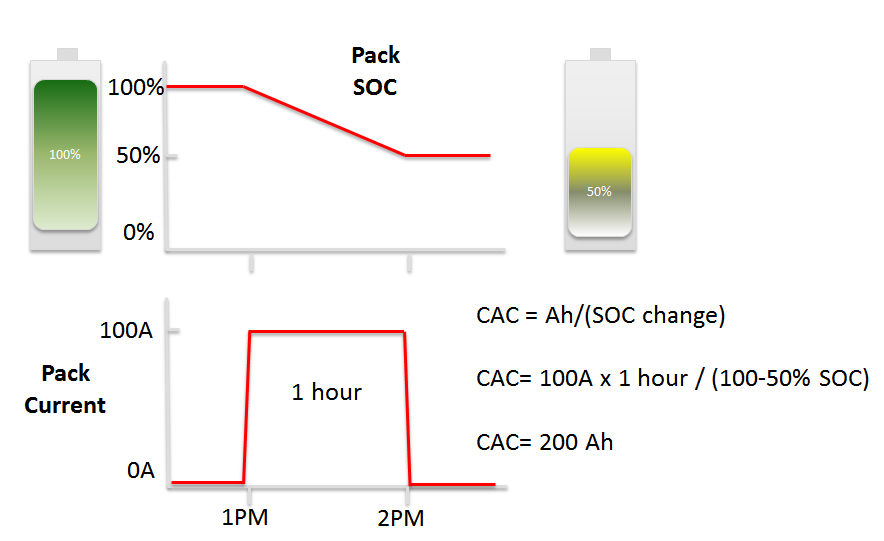
Capacity Specificationslink
The capacity of the HV battery has a direct correlation to the final range displayed to the customer. Calculated amp-hour capacity (CAC) is calculated by the high voltage battery management system by monitoring voltage change as well as current leaving and entering the HV battery. The simplified CAC calculation is indicated in the diagram below:
 |
|---|
The shunt is used to count amp-hours over a certain amount of time. That value and the delta state of charge (SOC) for that amp-hour amount are used to determine CAC. This calculation is done whenever there is a drive or charge cycle. However, values are only stored when the calculation is deemed accurate. There are many complex parameters that factor into the accuracy of that number, and the HVC decides when the number is accurate enough to update CAC. One of these parameters is rest time before and after the drive/charge cycle.
If the SOC is flat for a long time before and after the drive, it will result in the most accurate voltage/SOC measurement, which makes the CAC calculation accurate. Therefore, if a driver has constantly charged and drove without ever letting the vehicle rest at a fixed SOC, the CAC algorithm would not update during that time.
Brick balancinglink
Note
The capacity of a HV battery is limited by the brick with the lowest capacity.
When that brick is charging, it will gain voltage faster than other bricks. The high voltage battery management system will stop charge when any brick reaches its ceiling voltage (~4.2V). If one brick has a significantly lower capacity than others, the HV battery will be limited by that brick, which will get to 4.2V faster than the others. The brick with the lowest capacity is referred to as: min CAC.
Another limitation could come from bricks being imbalanced, or some bricks having a voltage higher/lower than others. This limits HV battery charging because a brick with higher voltage reaches the ceiling voltage early. It also applies during discharge when a brick with the lowest voltage hits the floor voltage earlier. This would cause the high voltage battery management system to open contactors due to low power.
To mitigate this imbalance, battery monitoring boards (BMBs) have some bleed resistors that can be placed and removed in parallel of each brick via a field-effect transistor (FET) relay. The BMB can put that resistor across the brick with the highest voltage, which would slightly discharge that brick and bring it back to the level of the other bricks. The BMB closes an FET which puts that resistor across the brick. The HVC will order BMB to put that bleed resistor across the brick with the highest voltage when Delta V is greater than 5mv and MinBrickV greater than 4.0v (~85% SOC) and HVC State is STANDBY.
Note
BMBs can also perform brick balancing when the HVC is asleep.
Diagnosticslink
System Health Monitoringlink
The HV battery is the source of power to the entire powertrain. The HV battery includes many subsystems from which any issue or unexpected behavior can affect other parts of the powertrain. These other ECUs in the powertrain will then trigger their own alerts in addition to the BMS ones. This situation leads to many alerts being reported by the vehicle which can make the diagnostic challenging. For instance, if contactor power was to be interrupted while in Drive, contactors would open, inverters and compressor would report erratic high voltage values and BMS would report loss of low voltage input power.
The Battery Management System (BMS) of the HV battery will trigger alerts when specific events are detected based on all the sensors in the HV battery and the data coming from other ECUs via CAN bus. Those alerts can have different impact on the vehicle behavior. From information only (alert only visible in logs or in Service Mode) or immediately firing the pyro-disconnect to cut the high voltage loop inside the HV battery. Information about these alerts can be found in Toolbox or Service Mode.
If a fault condition is detected while pack-contactors are closed, the system responds to limit or stop current operation. There are various levels of alerts, which lead to different responses from the system. For the HV battery ECUs (BMS, HVBMS, HVP, and/or HVBATT), the impact on the vehicle increases with the severity of the conditions causing an alert to set. The following table describes the different levels of alerts, from least to most impactful:
| Alert Level | Description |
|---|---|
| No Impact | The alert is not visible to the customer and only displayed in logs or service mode UI for information. |
| Reduced Max SOC | The vehicle can be driven and charged, but only up to a certain State of Charge (SOC). The HV battery cannot charge to 100% SOC. |
| Reduced Power or Limp Mode | The system limits power to prevent damage. The HVC sets a power limit for other powertrain components. |
| End Drive and No Restart | The current drive is not affected, but the vehicle may not be able to enter drive mode again. |
| Graceful Power Off | The system stops current flow and sends an alert to components to stop drawing power. The pack-contactors are opened when the current is low enough. |
| Immediate Shut Down | The system immediately stops current flow and opens the HV loop, even under load. Alerts are broadcast to the gateway, and contactors are opened. |
Diagnostic Strategylink
Different diagnostic tools are available to simplify getting to the initial issue that led to many ECUs reporting unexpected behavior and alerts; like Toolbox Articles and Service Mode Plus.
Service Mode Plus Diagnostic Panelslink
Service Mode Plus provides immediate visual identification of the health of specific vehicle subsystems. For the High Voltage system, three key panels are available:
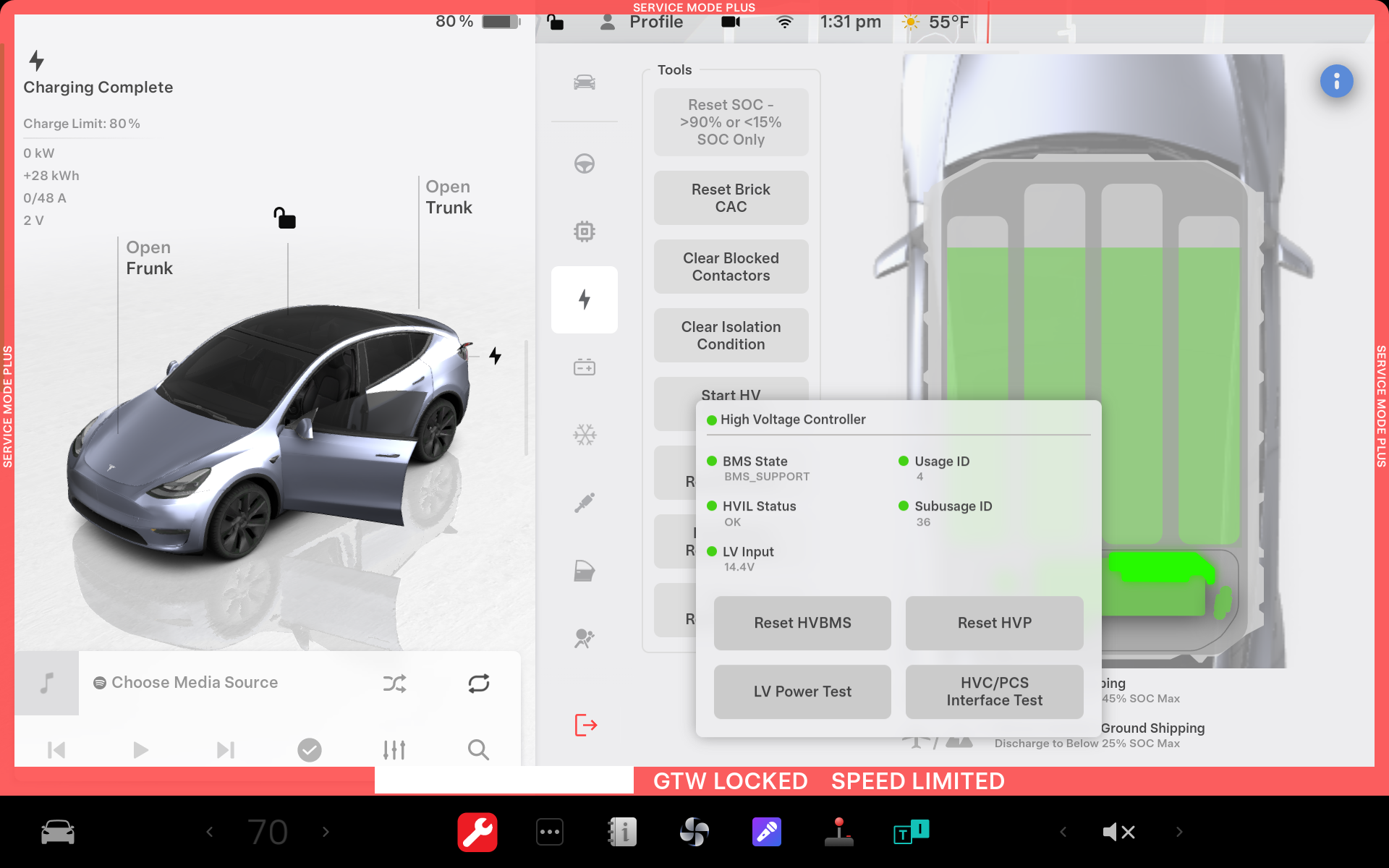
High Voltage Panellink
This panel displays the state of the high voltage distribution from the HV battery to the powertrain, including:
- HV battery status: operation mode, state of charge, HVIL status, and pyro disconnect status
- Pack contactors: state and temporary open button
- DC link: operational state of drive units, PCS, and HV A/C compressor
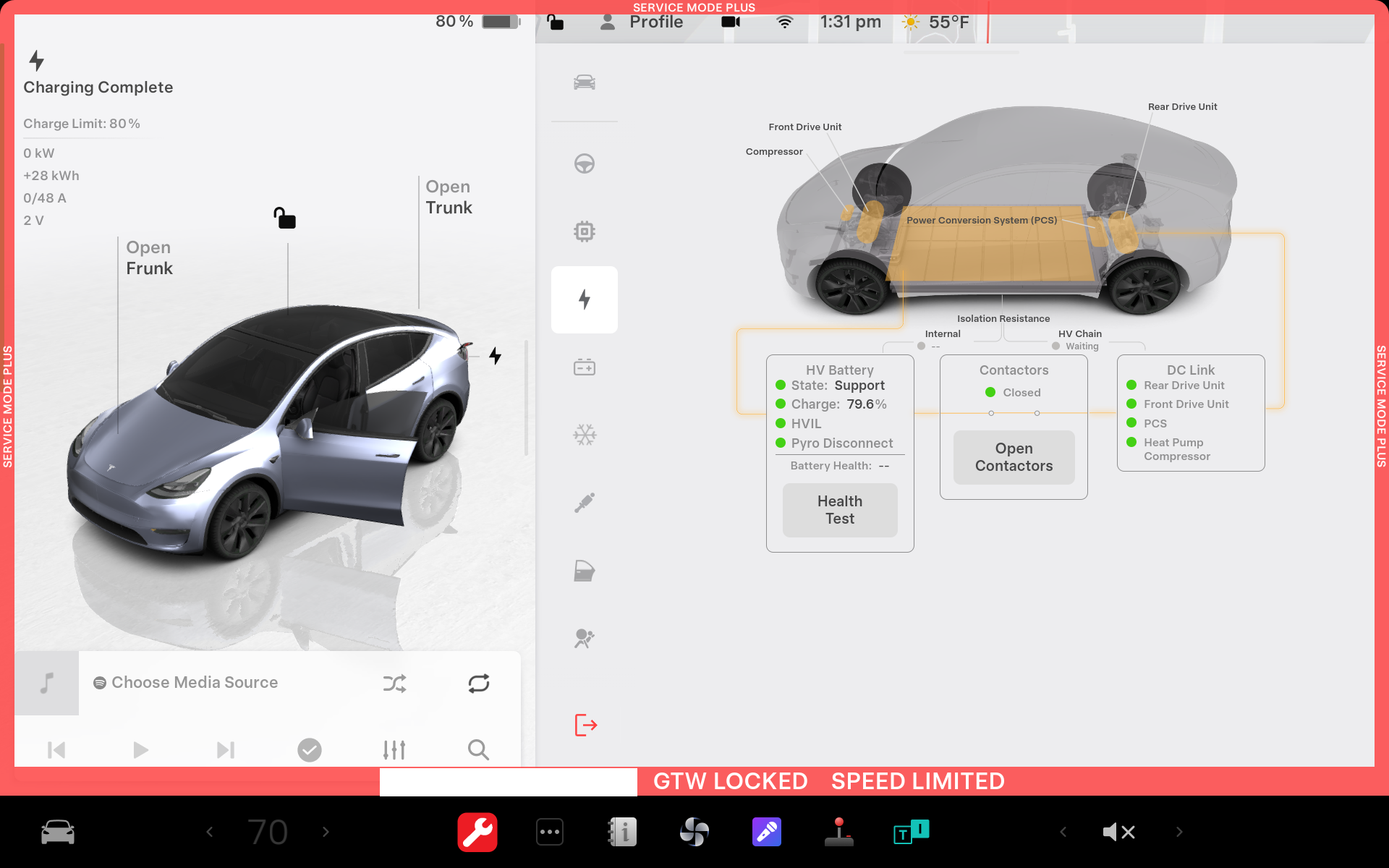 |
|---|
| High Voltage Service Panel |
HV Battery and HV Devices Panellink
This panel shows all connected and serviceable HV battery components, color-coded for easy issue identification. For example, when the main HV battery is selected, the panel displays key metrics, including:
- Min and max temperatures
- Min and max brick voltages
- Min and max Calculated Amp Hour Capacity (CAC)
- Pack voltage
- State of Health (SOH) status.
The panel displays vitals information for the following HV battery components:
- HVC
- PCS
- Contactors
- Fast Charge contactors
- Pyro-disconnect
- Shunts
 |
|---|
| HV Battery and HV devices service Panel |
HVIL Panellink
The overhead view representation of the vehicle displays all the HVIL over LV voltages available on the VEH CAN bus. The displays shows:
- HVIL output voltage
- HVIL intermediate voltage (after passing through the internal loop)
- Ancillary lid voltage and HVIL input voltage (final return to the HVC, sensed through a 60 Ohm resistor)
- Common mode voltage from all inverters (single for RWD and two for Dual Motor configurations)
- A button to force HVIL ON, useful for troubleshooting faulted HVIL conditions when the HVC turns off the HVIL power source.
- This feature allows for detailed analysis of HVIL states and voltages, even when the HVC would normally cut off the HVIL constant current source.
The overhead view representation of the vehicle displays the HVIL state of all the nodes reporting HVIL over CAN. The display shows:
This panel is most effective when an HVIL issue is currently present on the vehicle. However, it can still be useful even if the issue is not currently present, as it allows for:
- Monitoring voltages
- Checking HVIL node states
- Attempting to reproduce the issue while:
- Charging
- Driving (with someone else operating the vehicle)
The HVIL panel displays the HVIL status. In nominal mode, the panel shows that the contactors and HVIL status are closed, indicating normal operation.
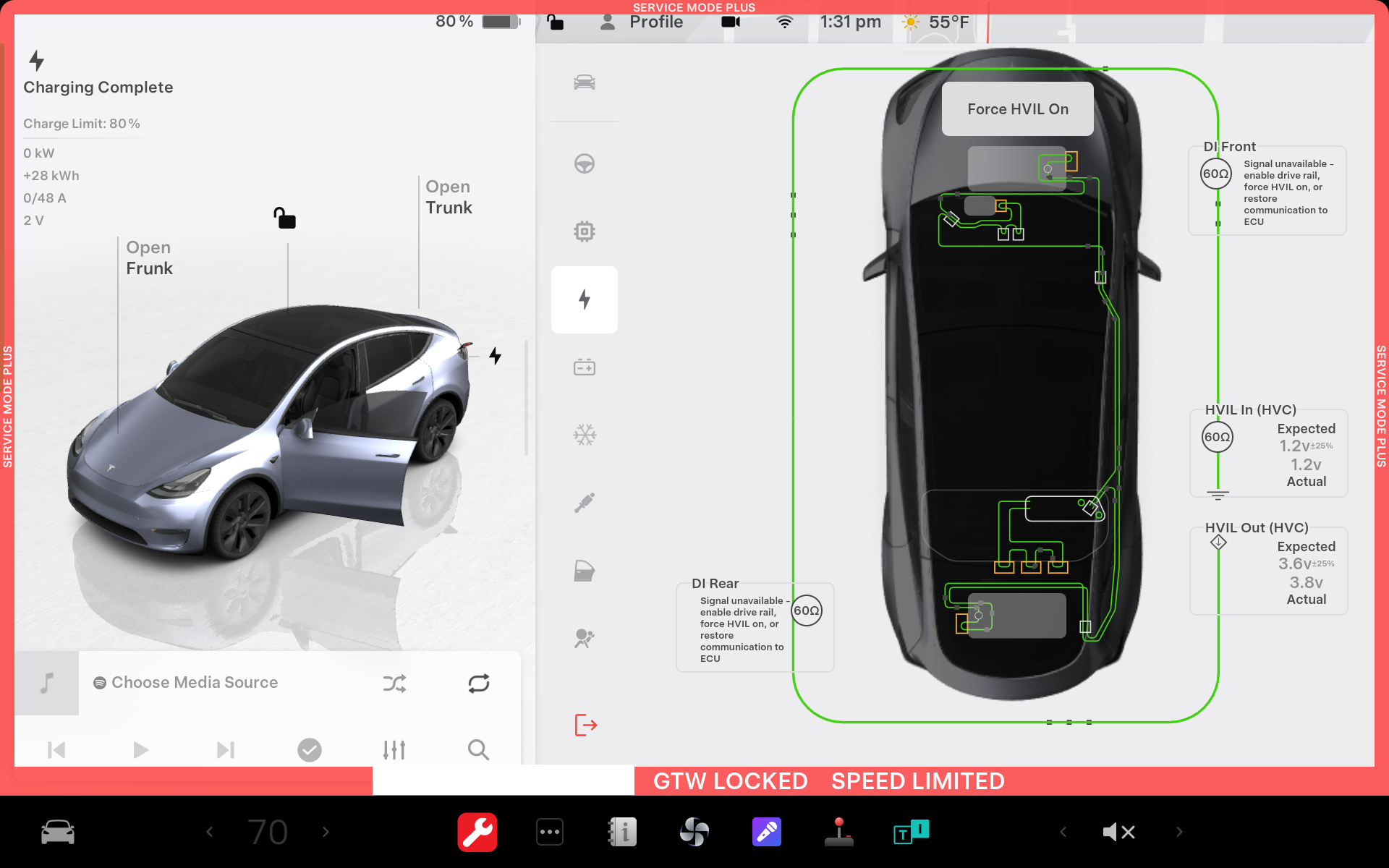 |
|---|
| HVIL over LV Service Panel |
The screenshots below show different HVIL failure modes and the associated visual of the HVIL panel.
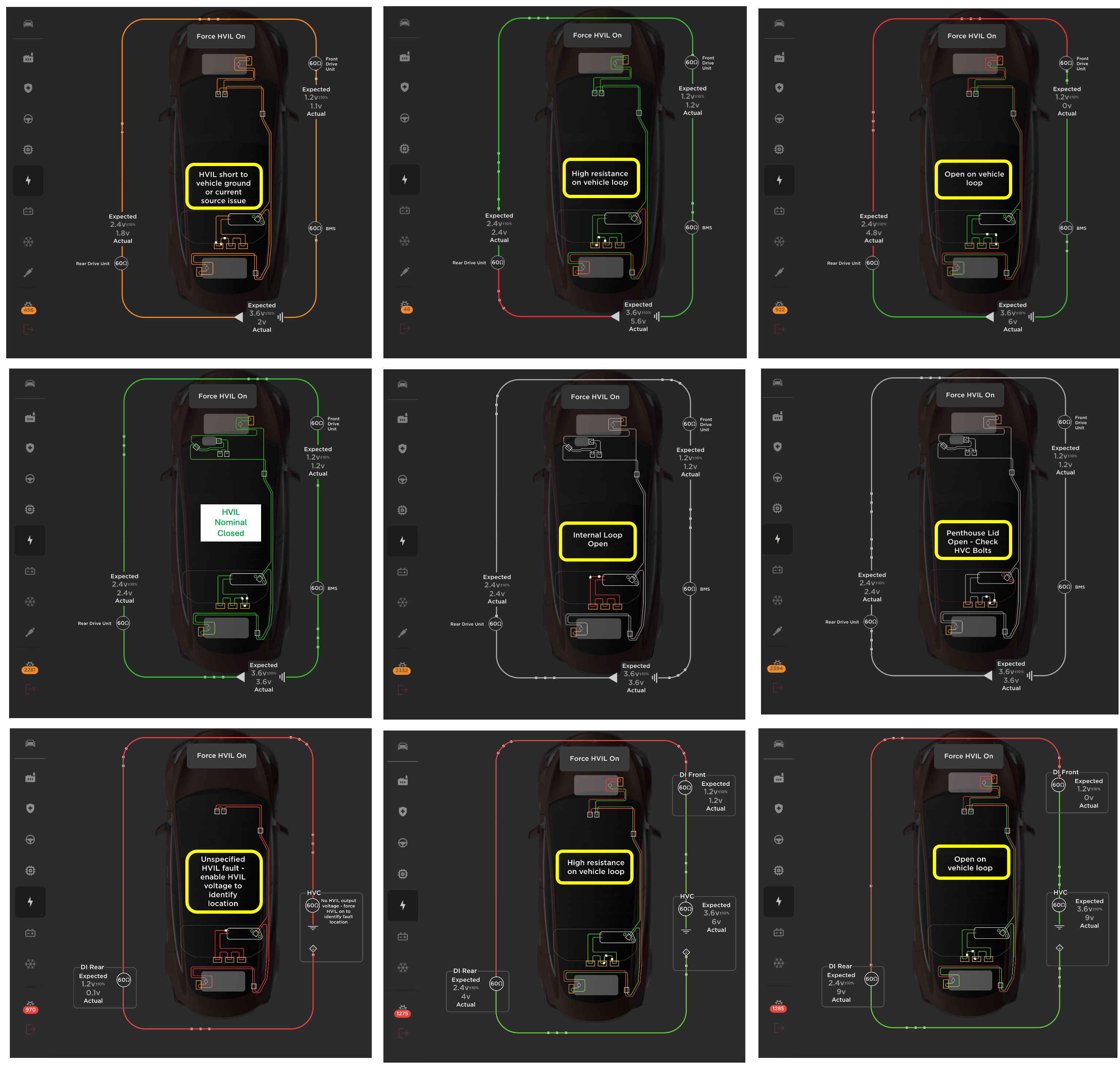 |
|---|
| The HVIL over LV Service Panel and Examples of HVIL Failures |
Repairlink
HV Battery and HV Devices Repair Routineslink
The HV Battery and HV Devices panel in Service Mode Plus provides access to the following repair routines:
- Reset SOH test
- Clear blocked contactors
- Clear isolation condition
- Start HV battery discharge using waste heat mode
- Replacement procedures for:
- Shunt
- HVC
- HV battery
Note
The replacement procedures for shunt, HVC, and the battery pack are also available in the HV procedure panel.
HV Procedures Panellink
The HV Procedures panel provides access to repair routines to be performed when replacing the following components:
- HVC
- HV shunt
- HV battery
- Drive unit
- Drive inverter
Important
Before powering down the vehicle and removing any of these components, it is required to back up the HVC and inverter memory systems using this panel.
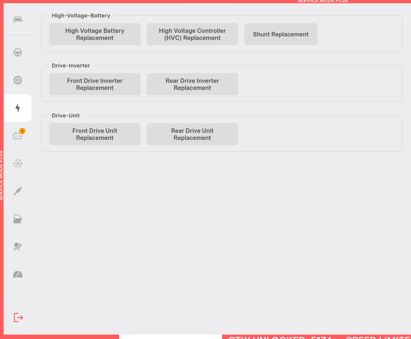 |
|---|
| HV Repair Procedures Panel |