Low Voltage Controllers and Wiringlink
Last updated: September 18, 2024
Circuit and Connector Diagramslink
Circuit diagrams show the path of all circuits in the vehicle. The connector reference shows the location and pinouts of all connectors in the vehicle.
Note
Connector references and circuit diagrams can be found on the Service website.
Low Voltage Architecturelink
Power Distributionlink
2021+ Model S features both a low voltage system and a high voltage system. The following devices are connected to both the high voltage and low voltage systems:
- Power Conversion System (PCS) (includes DC-DC)
- Drive inverters (front and rear)
- HVAC compressor
All other devices in the vehicle are powered solely by the low voltage system. The low voltage system features two independent sources of power:
- PCS (DC-DC)
- Low voltage battery
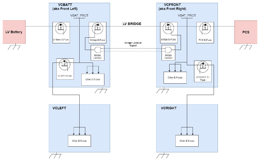
Power from the PCS goes to the front vehicle controller (VCFRONT) while power from the low voltage battery goes to the vehicle battery controller (VCBATT). The low voltage bridge (LV bridge) between these two controllers allows the PCS to provide the steady-state DC current for the entire low voltage system while simultaneously charging the lithium-ion low voltage battery to keep it topped-up while driving. The reason why there are two front controllers instead of one is to avoid single points of failure for all drive-critical systems.
Note
For more information on the lithium-ion low voltage battery, refer to Lithium-Ion Low Voltage Battery.
 |
|---|
| Low voltage power distribution |
High-level vehicle states:
- Sleep
- Accessory
- Drive
- Conditioning
- Over-The-Air (OTA)
- Self-Test
Note
For more information on vehicle states, including a detailed list of the possible states, refer to Vehicle Power States.
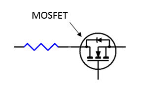
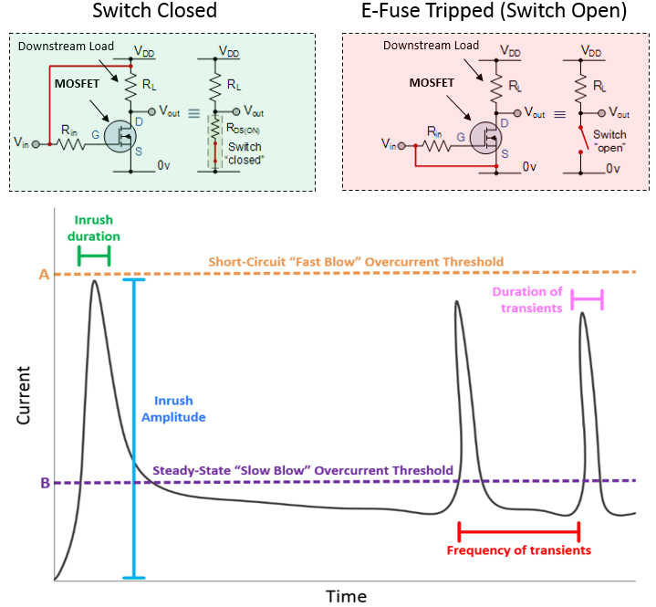
2021+ Model S electronic fuses (E-Fuses) consist of a metal oxide silicon field effect transistor (MOSFET) and a current sensor. When the current through the transistor exceeds either the firmware or hardware limits, the switch opens rapidly.
Types of E-Fuses:
- Discrete E-Fuse
- A MOSFET connected as a high side switch with a pull-up resistor, driven by an output pin.
- Configured as an open drain to deactivate downstream loads.
- Typical applications:
- High side driven devices that draw more than 25A.
- H-Bridge driven devices that draw more than 5A.
 |
|---|
| Discrete E-Fuse |
- Integrated Circuit (IC) E-Fuse
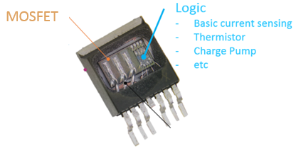
- A MOSFET connected as a high side switch, but with a separate chip integrated into its package that includes special hardware (like a current sensor, temperature sensor, thermistor, etc.) to help characterize and determine when to deactivate downstream loads.
- Typical Applications:
- High side driven devices that draw less than 25A.
- H-Bridge driven devices that draw less than 5A.
 |
|---|
| Integrated circuit E-Fuse |
Note
For more information on E-Fuses, refer to E-Fuses.
Powering and Controlling Connected Loadslink
Powering Loadslink
The low voltage controllers on 2021+ Model S use integrated circuits, an H-Bridge and a high side driver, to control the flow of power to the various loads connected to the vehicle controllers.
High-Side Driver:
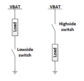
- A high side driver (shown below) is a transistor switch which can turn ON and OFF power to a downstream load. When the switch is ON, the battery voltage is applied to the load. The current that flows depends on the load; when the high side driver is ON, it does not affect the current. Many high side drivers feature a current sense inside the switch and turn off automatically in the event of an over-current. A high side driver that turns off when a specific current level is reached is called an E-Fuse.
Note
For more information on E-Fuses, refer to E-Fuses.
 |
|---|
| High side driver vs. low side driver |
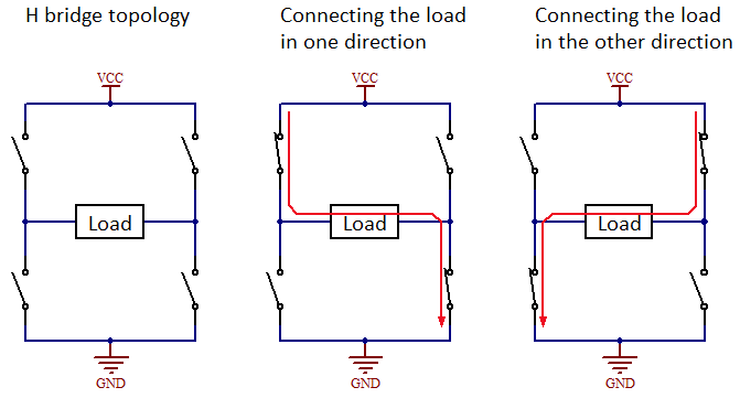
H-Bridge:
- An H-Bridge (pictured below) is a circuit which can apply voltage across a load in two directions. It is commonly used for controlling DC brushed motors, since each direction of current flow will spin the motor in a different direction. Some examples of DC motors controlled in this way are motors in the seat, steering column, and window lift.
Note
When probing the pins for an H-Bridge, make sure to measure across the two pins of the load. If measured from one of the H-bridge pins to ground, the readings may not match what the load is seeing.*
 |
|---|
| H-Bridge |
Harnesses and Passthroughslink
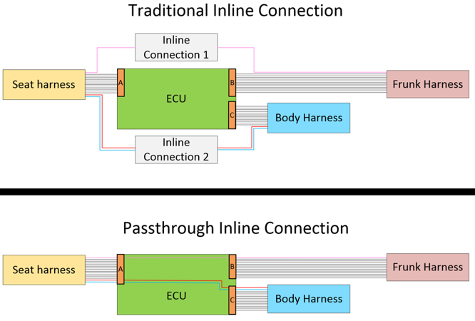
In addition to the use of traditional low voltage harnesses, 2021+ Model S also makes use of passthrough connections similar to Model 3 and Model Y in order to reduce the number of the inline connectors and wire splices required to connect the controllers in the vehicle.
A passthrough connection is a metal trace on a Printed Circuit Board (PCB) on one of the vehicle's low voltage controllers and acts like a wire harness extension. This trace does not touch any other circuitry on the PCB; it's just a "wire."
Example of a passthrough vs. traditional inline connector:
- By using traditional inline connectors, the design requires connectors A, B, and C along with inline connectors 1 and 2.
- By using passthroughs, the design only requires connectors A, B, and C. Inline connectors 1 and 2 are not required.
 |
|---|
| Traditional inline connectors vs. passthroughs |
Note
For more information on CAN and vehicle communication architecture, refer to Communication Architecture.
Cut-Loopslink
Power wires for the high voltage pack contactors and restraint control module are routed throughout the vehicle into two loops of wire. After a crash event, first responders can cut these wires to disconnect the high voltage battery pack from the vehicle and disable air bags.
 |
|---|
| First responder cut-loops |
Controllerslink
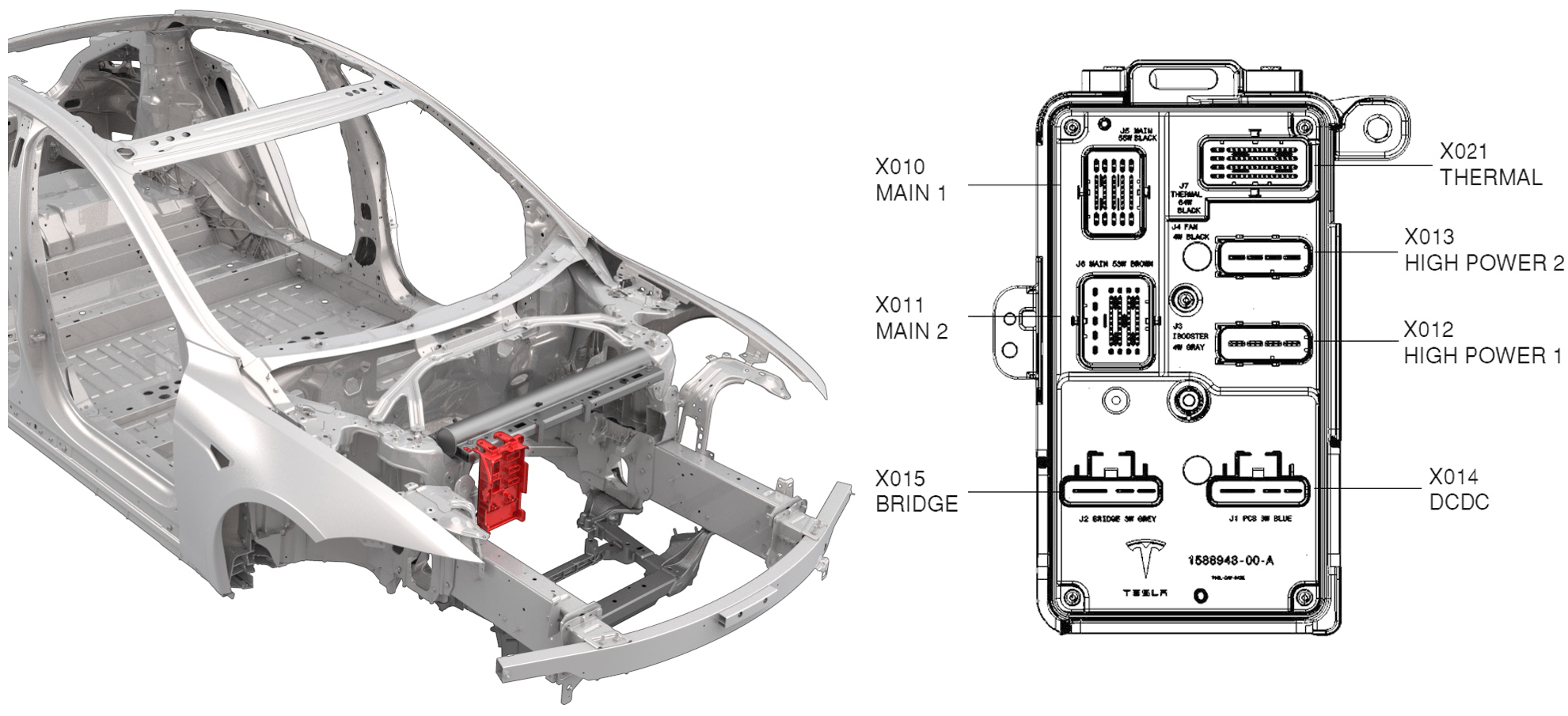
Front Vehicle Controller (VCFRONT)link
 |
|---|
| 1. J5 / X010 / Main 1 - active louver, EPAS2, Homelink, front DI, horn, radar, right fascia lights, windshield washer, right headlight, frunk latch. 2. J6 / X011 / Main 2 - air suspension controller, MCU, VEH CAN, PARTY CAN, brake fluid level sensor, right repeater, bridge sync, front BLE. 3. J2 / X015 / THIC bridge - EPAS2, bridge. 4. J7 / X021 / thermal - EXVs, temperature sensors, compressor LV power, coolant valve, coolant level sensor, powertrain pump, chiller pump, VEH CAN. 5. J4 / X013 / high power 2 - radiator fan. 6. J3 / X012 / high power 1 - Autopilot 2, iBooster, MCU audio, windshield wiper. 7. J1 / X014 / THIC DCDC - PCS, VCRIGHT. |
Power Distributionlink
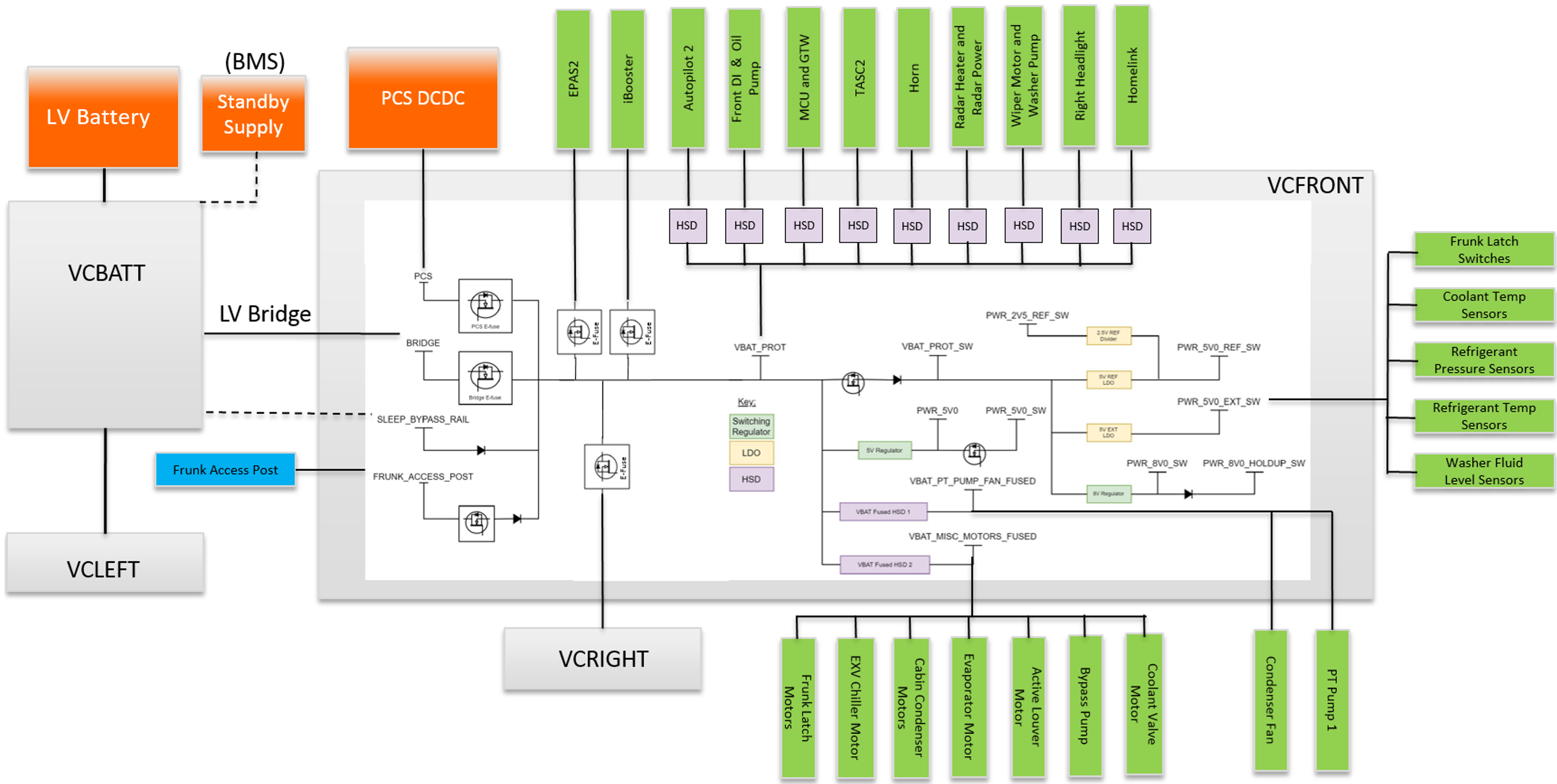
VCFRONT is located in the front of the vehicle, under the hood. The controller is powered by VCBATT and the PCS, depending on the vehicle state. For more information on H-Bridges and high side drivers, refer to Controlling and Powering Loads.
 |
|---|
| VCFRONT power distribution and major loads |
Communicationlink
VCFRONT supports both controller area network (CAN) and local interconnect network (LIN) communication, with information being relayed to devices connected to the controller by a combination of direct input / output (I/O), CAN, LIN, and passthrough connections. VCFRONT is connected to, and communicates on, both the vehicle (VEH) and private (Party) CAN-Buses. For more information on vehicle communication architecture, refer to Communication Architecture.
Vehicle Battery Controller (VCBATT)link
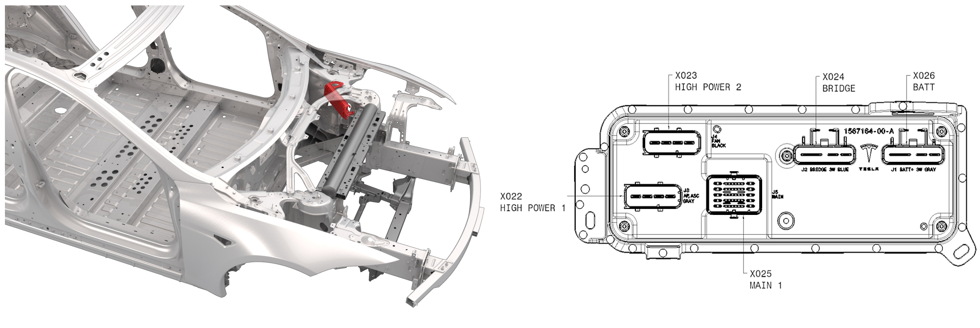 |
|---|
| 1. J4 / X023 / high power 2 - radiator fan. 2. J2 / X024 / THIC bridge - bridge, VCLEFT. 3. J1 / X026 / THIC B+ - VBAT (LV Battery), EPAS1. 4. J3 / X012 / high power 1 - Autopilot 1 HCU, MCU logic, air suspension compressor. 5. J5 / X025 / main - left headlight, HCU valve, VEH CAN, Party CAN, battery backup siren, E-Fuse lockout, standby supply, left fascia lights, Li-Ion LV battery, bridge sync, battery coolant pump, radiator coolant pump, trunk switch. |
Power Distributionlink
VCBATT is a combination of an intelligent battery sensor, a fuse box, and a body controller on a single Printed Circuit Board Assembly (PCBA). For more information on H-Bridges and high side drivers, refer to Controlling and Powering Loads.
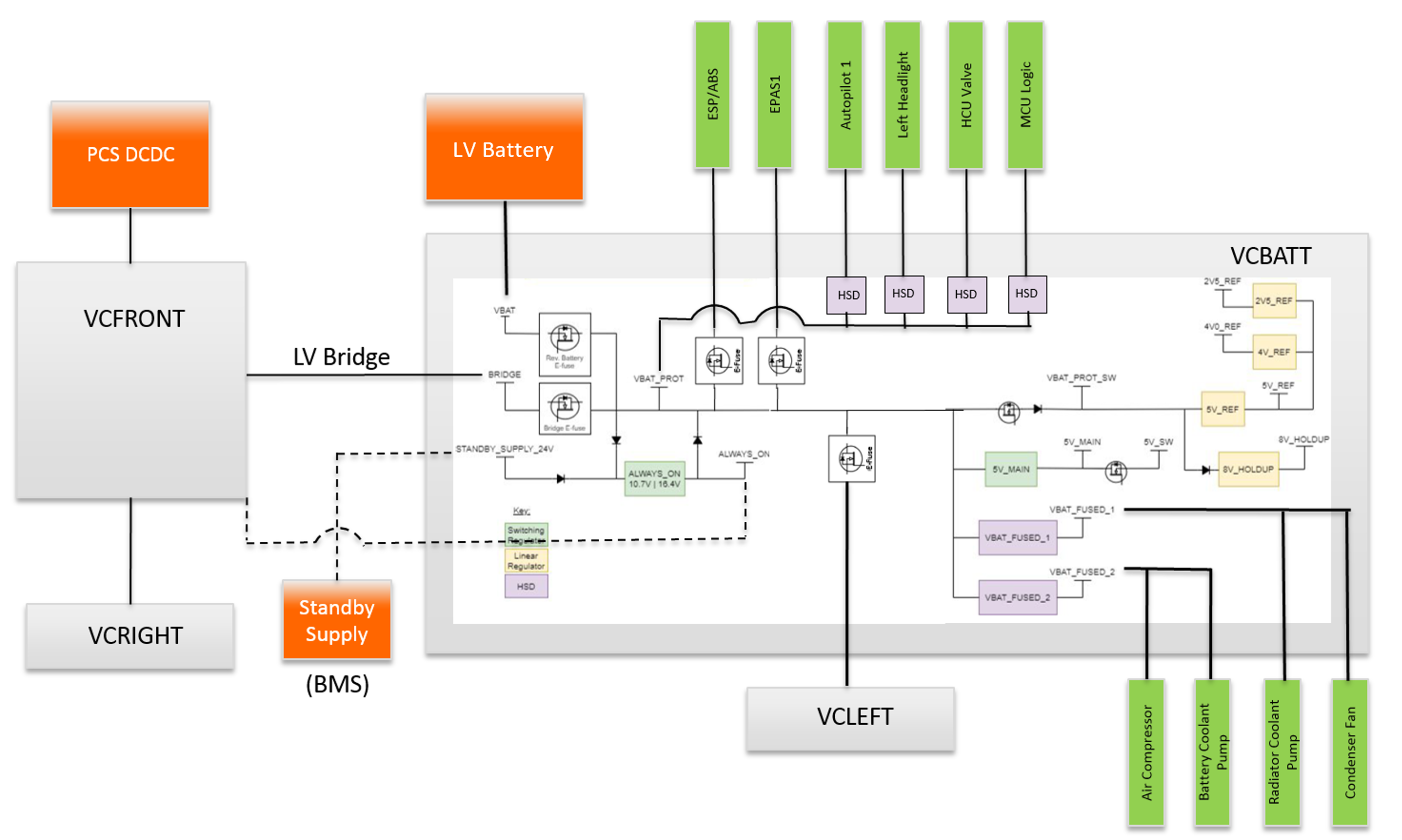 |
|---|
| VCBATT power distribution and major loads |
Communicationlink
VCBATT supports both CAN and LIN communication, with information being relayed to devices connected to the controller by a combination of direct I/O, CAN, LIN, and passthrough connections. VCBATT is connected to, and communicates on, both the vehicle (VEH) and private (Party) CAN-Buses. For more information on the vehicle communication architecture, refer to Communication Architecture.
Left Vehicle Controller (VCLEFT)link
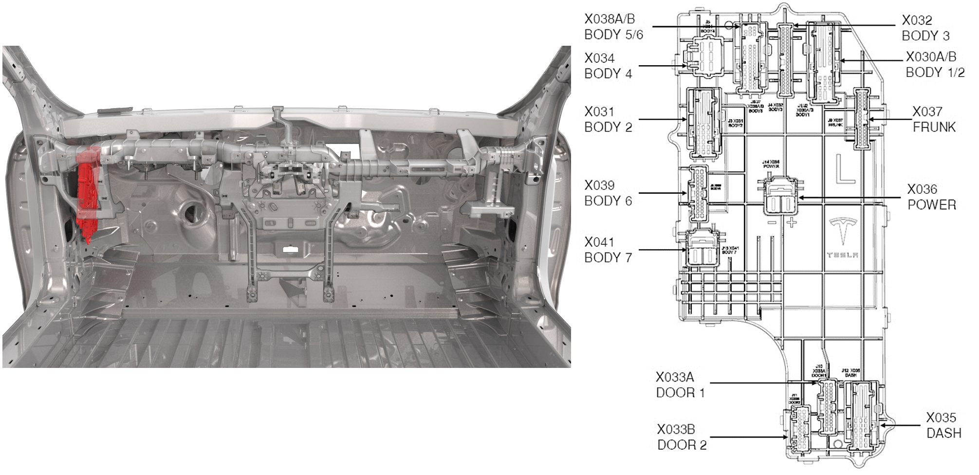 |
|---|
| 1. J6/J7 / X038 / body ⅚ - rear door handles and switches, rear oil pump, USB chargers, second row door LEDs, second row buckle switches, 2nd row fold flat switches, VEH CAN, front door audio passthroughs. 2. J5 / X034 / body 4 - front and rear door ECUs, front and rear seat ECUs, trailer aux. 3. J3 / X031 / body 2 - console and trunk power sockets, impact sensor passthroughs, inductive chargers, vanity light LEDs, map light LEDs, left body side tail light, left brake light, rear window switch. 4. J8 / X039 / body 6 - liftgate struts, liftgate switch, center console LED, second row door latch. 5. J13 / X041 / body 7 - trailer ECU. 6. J10 / X033A / door 1 - left mirror, left windows, left door latches . 7. J11 / X033B / door 2 - door handle ECU, window switchpacks, front door audio passthroughs, front door latch open switch, mirror tilt postion. 8. J4 / X032 / body 3 - B-Pillar BLE and NFC, rear door latch open switch, front door pressure sensor passthrough, second row airwave, brake pedal NO switch, rear door handle ECU. 9. J1 / X030A / body 1 - accelerator pedal, Party CAN, center console LEDs, liftgate struts, second row window motor, charge port ECU. 10. J2 / X030B / body 2 - parking brake. 11. J9 / X037 / frunk - E-Fuse lockout, impact sensor passthroughs, Party CAN, RCM. 12. J1 / X036 / power - power in from VCBATT. 13. J12 / X035 / dash - display tilt motor and encoder, steering column tilt and telescope motors, VEH CAN, OBD port, Party CAN, left HVAC vanes, steering wheel ECU, footwell LED, steering column ECU. |
Power Distributionlink
VCLEFT gets power from VCBATT, depending on the vehicle state, via a dedicated high current E-Fuse. VCLEFT manages the majority of devices on the left hand side of the vehicle via multiple internal micro controllers. Information is relayed to devices by a combination of direct I/O, CAN, LIN, and passthrough connections. VCLEFT is an always-on component, meaning it receives power during sleep and is always on. For more information on H-Bridges and high side drivers, refer to Controlling and Powering Loads.
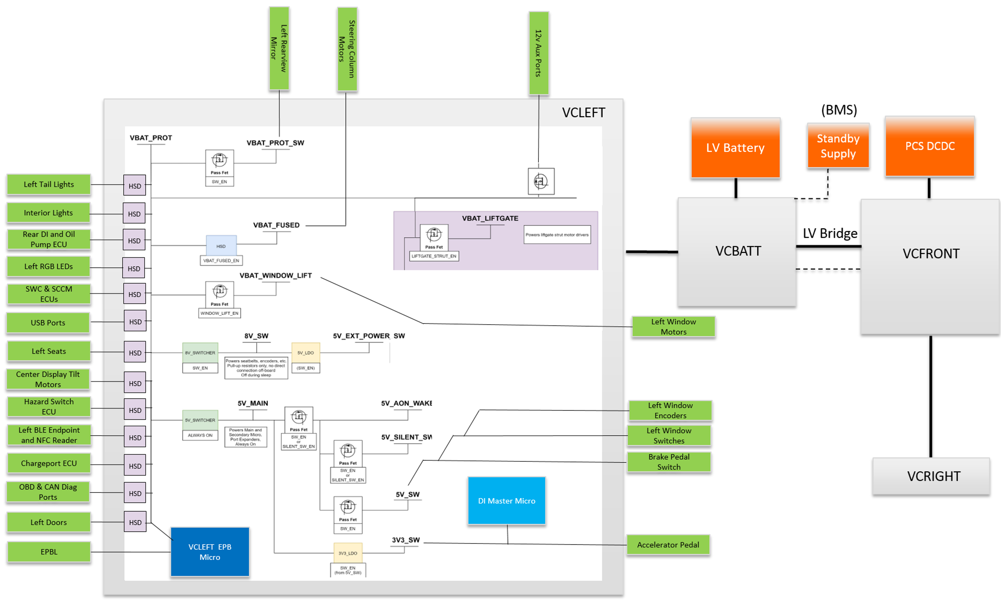 |
|---|
| VCLEFT power distribution and major loads |
Communicationlink
VCLEFT supports direct I/O, CAN, and LIN communication. The main micro controller and Electronic Park Brake (EPB) micro controller communicate on both vehicle and private CAN. They are distinct devices even though they are on the same PCBA. For more information on the vehicle communication architecture, refer to Communication Architecture.
Right Vehicle Controller (VCRIGHT)link
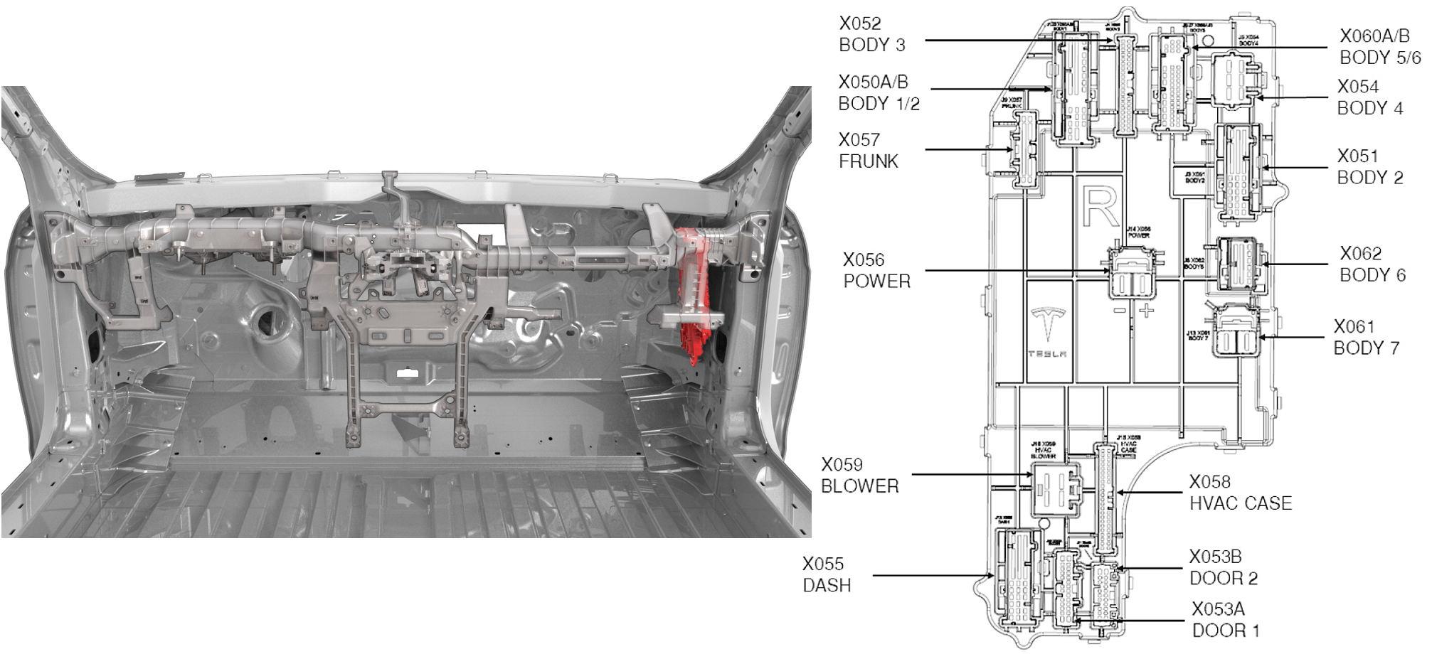 |
|---|
| 1. J4 / X052 / Body 3 - liftgate shutface switch, liftgate pinch sensor, liftgate latch, VCSEC, Party CAN, rear door handle ECU, rear window. 2. J6 / X060A / body 5 - VEH CAN, park CAN, 2nd row buckles and fold flat switches, ECAL standby power, 2nd row door ECU, interior radar. 3. J7 / X050B / body 6 - 2nd row puddle lamp LED, vanity light LED. 4. J9 / X057 / frunk - liftgate switch passthrough, E-Fuse lockout, HV controller, VEH CAN , park CAN, HVAC air temperature sensor, front USS. 5. J16 / X059 / blower - HVAC blower motor. 6. J12 / X055 / dash - IP audio passthroughs, glovebox release, footwell LED, HVAC cabin and duct temperature sensors, right HVAC vane actuators. 7. J1 / X050A / body 1 - liftgate side tail lights, right body side tail light, CHMSL, chassis CAN, rear drive unit oil pump, liftgate latch release. 8. J2 / X050B / body 2 - right parking brake, rear USS, radio tuner, HV contactors. 9. J4 / X052 / body 3 - Party CAN, liftgate pinch sensor, VCSEC, 2nd row door handle ECU and switches. 10. J5 / X054 / body 4 - front door controller, rear seat controller, rear glass heater, premium amplifier. 11. J3 / X051 / body 2 - front door audio passthrough, rear BLE endpoints, right B-Pillar BLE, door pressure sensor passthrough. 12. J5 / X056 / power - power in from VCFRONT. 13. J8 / X062 / body 6 - rearview mirror dim, interior camera LED, vanity light LED, OCS ECU, liftgate cinch motor. 14. J15 / X058 / HVAC case - 2nd row HVAC bypass actuator, HVAC intake actuator, HVAC defrost actuator, HVAC defrost and evaporator temperature sensors. 15. J10 / X053A / door 1 front door latch, front door window motor and encoder, right mirror, window switchpack, map pocket lights, first row door ECU. 16. J11 / X053B / door 2 - front door audio passthroughs, front door pressure sensor passthrough. |
Power Distributionlink
VCRIGHT is powered by VCFRONT, depending on the vehicle state, via a high-power dedicated E-Fuse. The controller manages the majority of devices on the right-hand side of the vehicle via multiple internal micro controllers. Information is relayed to devices by a combination of direct I/O, CAN, LIN, and passthrough connections. For more information on H-Bridges and high side drivers, refer to Controlling and Powering Loads.
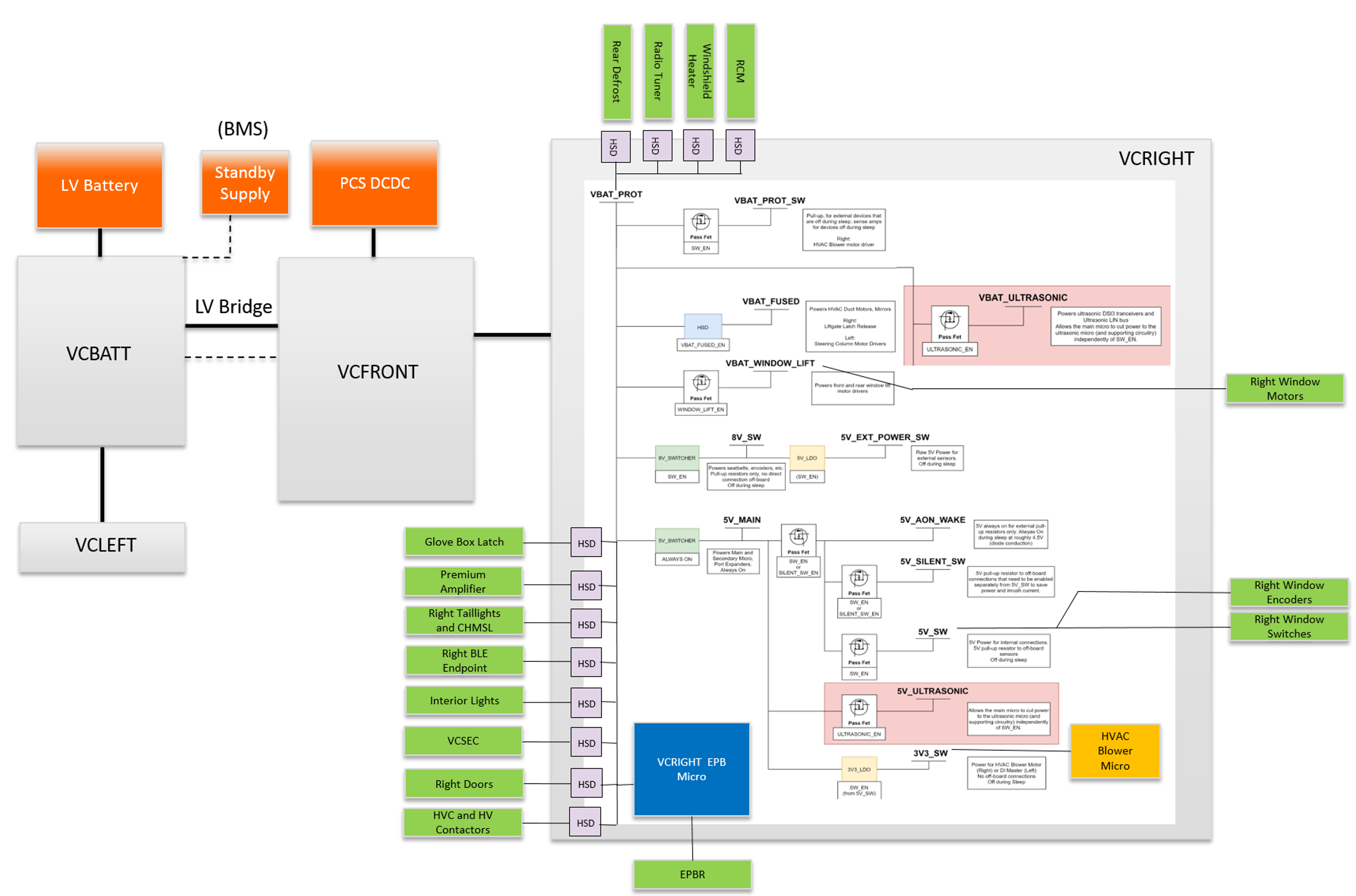 |
|---|
| VCRIGHT power distribution |
Communicationlink
VCRIGHT supports direct I/O, CAN, and LIN communication. The main micro controller and EPB micro controller communicate on both vehicle and Private CAN. The ultrasonic micro controller communicates on chassis and Park CAN. The micro controllers are distinct devices even though they are on the same PCBA. For more information on the vehicle communication architecture, refer to Communication Architecture.
E-Fuseslink
Overviewlink
An E-Fuse is a solid state switch, or a transistor, and a current sensor. When the current through the transistor exceeds either the firmware or hardware limits, the switch opens rapidly. The E-Fuse replaces the traditional relay and fuse combination, and it allows for better handling of electrical faults and protection of harnesses if a fault does occur. Traditional fuses can take several seconds to trip, while an E-Fuse can interrupt current flow in a matter of milliseconds. In order to use E-Fuses, detailed electrical behavior for each load is required to differentiate between a false positive and a true fault. E-Fuses also significantly impact the concept of power rails because they allow for firmware-controlled virtual grouping of individual E-Fuses into virtual power rails, which are referred to as vehicle states.
Note
2021+ Model S doesn't use traditional fuses. 2021+ Model S only uses E-Fuses.
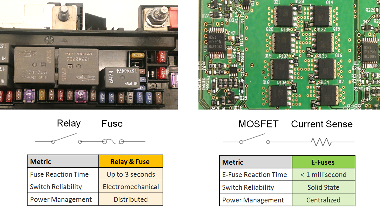 |
|---|
| Traditional fuse (left) vs. E-Fuse (right) |
Operationlink
An E-Fuse functions like a traditional fuse (opens circuit when too much current is flowing through it), except it reacts faster.
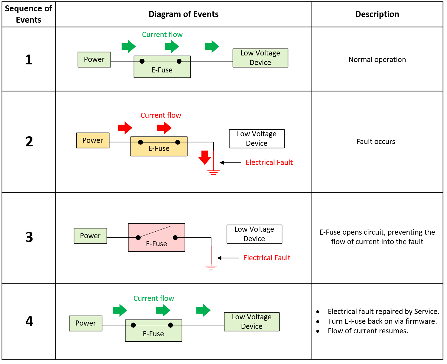 |
|---|
| E-Fuse overview |
Trippinglink
If an E-Fuse trips, a fault signal will be read by the micro controller. Depending on the type of load the E-Fuse is connected to, the construction of the E-Fuse, and the vehicle state when the fault occurs, the behavior may be to enter either Auto-Retry or Latch-Off mode. Some E-Fuses may only enter Latch-Off, some always Auto-Retry, and some are configurable. In Tesla applications, most fall under the configurable category.
After an E-Fuse trips, the firmware does not immediately try to re-enable the E-Fuse. The design intent is for the E-Fuse to only trip when an electrical fault occurs. The E-Fuse should only be re-enabled after the electrical fault has been repaired . A few exceptions to this statement exist:
- Capacitive inrush problems. In this scenario, the firmware quickly re-enables E-Fuses to precharge downstream capacitive loads.
- User-accessible ports such as the LV power socket, USB ports, and trailer light ECU can be reset by cycling control to those outputs to recover them.
Auto-Retry behavior:
-
The intent of Auto-Retry is to have the firmware intervene when a fault is detected, using the fault signal sent to the micro controller, and to immediately disable the E-Fuse until predefined conditions are met to re-enable the E-Fuse.
-
When an E-Fuse is capable and configured for Auto-Retry, it will turn off, wait a period of time, then attempt to turn back on for a period of time as determined by the firmware.
Latch-off behavior:
- When a latch-off E-Fuse trips, it will turn off and remain off until the firmware resets the E-Fuse. An E-Fuse reset is typically achieved by toggling the enable signal OFF to ON. The enable signal will always be reset in the event of a power on reset of the micro controller, unless the enable line is locked out.
Lock-out behavior:
- There are specific conditions where the firmware prevents toggling of the enable line via separate protection circuitry (which is only done for E-Fuses deemed drive-critical, not all E-Fuses). This is true in the Drive state, where it is unacceptable for the firmware to actively turn off any E-Fuse. This does not mean the E-Fuse cannot trip, only that the micro controller cannot turn off or toggle the E-Fuse enable signal. This lock-out persists on the vehicle controllers even through a reset of the main micro controller. The only way to unlock the enable signal is to leave the Drive state.
Types of E-Fuseslink
External FET (discrete):
A discrete E-Fuse uses a MOSFET connected as a high side switch with a pull-up resistor, driven by an output pin configured as an open drain to deactivate downstream loads. A high side driven switch means that the load is after the switch, with one end of the load tied to ground. Conversely, a low side driven switch is the opposite, meaning the switch is after the load (before ground), with one end of the load tied to power.
- Typical applications:
- High side driven devices that draw more than 25A.
- H-Bridge driven devices that draw more than 5A.
- Discrete E-Fuses are typically composed of multiple components, including:
- Gate drive circuit (IC or discrete).
- Charge pump (can be integrated into a gate drive IC, or can be external).
- Current sense amplifier (can be integrated into a gate drive IC, or can be external).
- External N-channel Field Effect Transistor (FET).
- External low side flyback diode or low side FET.
- External current sense resistor.
- Inputs typically include:
- Enable.
- Reset.
- Miscellaneous settings such as gate drive current, VDS overcurrent threshold, and current-chop threshold.
- Outputs typically include:
- High-accuracy current sense.
- Fault.
Internal FET (Integrated Circuit):
An Integrated Circuit (IC) E-Fuse uses a MOSFET connected as a high side switch, but with a separate chip integrated into its package that includes special hardware (like a current sensor, temperature sensor, thermistor, etc.) to help characterize and determine when to deactivate downstream loads.
- Typical applications:
- High side drive devices that draw less than 25A.
- H-Bridge drive devices that draw less than 5A.
- Contains an off-the-shelf IC which typically consists of:
- An N-channel FET.
- Charge pump (used to increase or decrease voltage across a load).
- One or more temperature sensors.
- Inputs typically include:
- Enable.
- Reset.
- Outputs typically include:
- Low-accuracy current sense.
- Fault.
Types of Fault Protectionlink
Current-based fault protection:
Current-based fault protection measures a voltage drop across an external current sense resistor to determine current flow. If the current exceeds a configurable threshold, the E-Fuse opens the circuit. This type of protection is most often associated with discrete E-Fuses. An E-Fuse with current based protection is relatively easy to match with the harness to make sure that there is adequate protection, but it is more difficult to engineer to prevent false trips because extensive characterization of the downstream loads is required.
 |
|---|
| Current-based E-Fuse fault detection |
Discrete high side E-Fuses typically feature two levels of overcurrent protection:
-
Short-circuit overcurrent protection: If current flowing through the E-Fuse exceeds the short-circuit overcurrent threshold, the E-Fuse will trip within 1 millisecond indicating a low-resistance "hard" short circuit has occurred.
-
Steady state overcurrent protection: Some devices draw large bursts of current for short durations. To make sure these devices function properly, the E-Fuse allows current to exceed the steady-state overcurrent threshold, but only for a short period of time. However, the MOSFET will overheat if current of magnitude A flows through them for an extended period of time. Therefore, if the steady-state overcurrent threshold is exceeded for an extended period of time, the E-Fuse will trip.
Examples of devices that use these E-Fuses include:
- The main E-Fuses on the VCFRONT and VCBATT (iBooster, ESP, PCS, VCLEFT, VCRIGHT, EPAS).
- High-current H-Bridges (seat motors, steering column motors, parking brake motors, window lift motors).
Temperature-based fault protection:
Temperature-based fault protection is usually associated with integrated circuit style E-Fuses, which feature an internal thermistor (a resistor whose resistance is dependent on temperature). If the thermistor becomes too hot, the E-Fuse opens the circuit. These devices are typically not configurable. This type of fault protection is more tolerant to loads and conditions that are not fully characterized, but it is affected by ambient temperature.
On-Board Diagnostics (E-Fuse Self-Checks)link
Self-check steps for E-Fuses with no upstream turn-off path include:
- Measure voltage on output of E-Fuse (verify E-Fuse is off).
- Turn on E-Fuse.
- Measure voltage on output of E-Fuse (verify E-Fuse is on).
- Turn off E-Fuse via fault injection.
- Measure voltage on output of E-Fuse (verify E-Fuse is off).
- Turn on E-Fuse.
The purpose of these self-checks is to verify the E-Fuses can be turned off properly prior to shifting the vehicle into drive. For more information on how E-Fuses are utilized, refer to the HV Architecture - Power Electronics section.
Vehicle Power Stateslink
Overviewlink
The E-Fuses in VCFRONT control the flow of low voltage power throughout the vehicle and are grouped together in the vehicle firmware to create virtual power "rails" known as vehicle states. The table below lists all the virtual power states VCFRONT can inhabit.
Vehicle power states
| Power State | State Description |
|---|---|
| Accessory | The Accessory state is intended to support in-vehicle entertainment and HVAC features. |
| Accessory Plus | Intended for the manufacturing environment. When VCFRONT is not in Drive, if Unified Diagnostics Services (UDS) security access is granted, VCFRONT shall enter Contactors Open (self-test), Accessory (self-test), or Accessory Plus (self-test) states for a fixed timeout based on the input parameters of the routine. |
| Conditioning | The Conditioning state is intended to support (but is not limited to) vehicle preconditioning, postrun (cooling powertrain), maintaining pack temperature, low voltage battery support, heating to charge, charge, and Sentry mode. |
| Drive | Whenever PNRD is available on the user interface (UI), the vehicle is in a Drive state even if the vehicle is not in the Drive gear. |
| HV Up Standby | HV Up Standby is an intermediate state that is used to evaluate which HV Up state VCFRONT should transition to, or if it should transition to LV Awake. |
| LV Awake | The LV Awake state is intended to only power ECUs essential for system monitoring. Upon entering LV Awake, the VCFRONT will re-enable its internal switched rails and re-initialize its brushless motor drivers (battery pump, powertrain pump, and radiator fan). |
| Sleep Shutdown | On entering Sleep Shutdown, VCFRONT turns off the high-current power feeds to all permanently powered devices if the current on the sleep bypass E-Fuse is < 3A. |
| Sleep Standby | In this state, VCFRONT executes sleep shutdown procedures and sends commands to put buses to sleep. |
| LV Shutdown | In this state, all switched power ECUs are turned off. |
| OTA | In this state, VCFRONT will make all E-Fuse channels available to control via UDS for use during firmware updates. |
| Battery Post Wake | In Battery Post Wake, the VCFRONT will not turn on any loads except one that allows the frunk latch to actuate and disable all reverse battery protection FETs. |
Low Voltage State Machinelink
The low voltage state machine could be considered the master state machine of 2021+ Model S, since it powers VCFRONT. Each state has implications on power distribution to vehicle components as well as influencing the state machines of other controllers, and inhibiting or triggering certain functions or processes. Below are some of the key low voltage state machine states, with brief descriptions relating to power management and examples of inhibiting or triggering processes.
Note: The transition examples are not the complete list, and there are intermediate states not captured in this section due to the complexity of the state machine. Note: To learn more about state machines in general, a good starting point is to research the term "finite-state machine."
Power State Truth Tablelink
The Power State Truth Table gives record of which ECUs are powered in the core low voltage State Machine vehicle states.
- 1 = Powered, some ECUs have a shut down procedure that requires a fixed amount of time before the power feed can be safely cycled.
- 0 = Shut down.
- C = Conditional. Some ECUs may be on in vehicle states when they are normally not due to requiring time to shut down, or because of a keep power request. An example is the restraint control module in a crash event.
Power State Truth Table
| Component | Off | Conditioning | Accessory | Accessory Plus | Drive | Going Down Time (ms) |
|---|---|---|---|---|---|---|
| Air suspension | 1 | 1 | 1 | 1 | 1 | 0 |
| Autopilot (Parker, Pascal) | 1 | 1 | 1 | 1 | 1 | 0 |
| Autopilot (Parker, Aurix) | 1 | 1 | 1 | 1 | 1 | 0 |
| EPAS3P | 0 | 0 | 0 | 1 | 1 | 2000 |
| EPAS3S | 0 | 0 | 0 | 1 | 1 | 2000 |
| ESP | C | C | C | 1 | 1 | 2000 |
| iBooster | 0 | 0 | 1 | 1 | 1 | 12000 |
| Front drive inverter | 0 | C | C | 1 | 1 | 2000 |
| HVAC compressor | 0 | 1 | 1 | 1 | 1 | 0 |
| Homelink | 1 | 1 | 1 | 1 | 1 | 2000 |
| Left headlight | 1 | 1 | 1 | 1 | 1 | 3000 |
| Right headlight | 1 | 1 | 1 | 1 | 1 | 3000 |
| MCU logic | 1 | 1 | 1 | 1 | 1 | 0 |
| MCU audio | 0 | 1 | 1 | 1 | 1 | 0 |
| Front drive unit oil pump | 0 | 0 | 0 | 1 | 1 | 2000 |
| PCS | 1 | 1 | 1 | 1 | 1 | 0 |
| Radar | 0 | 0 | 0 | 1 | 1 | 0 |
| VCLEFT | 1 | 1 | 1 | 1 | 1 | 0 |
| VCRIGHT | 1 | 1 | 1 | 1 | 1 | 0 |
| Windshield wiper ECU | 0 | 0 | 1 | 1 | 1 | 2000 |
| Pump1 and condensor fan | 1 | 1 | 1 | 1 | 1 | 2000 |
| Pump2 and air compressor | 1 | 1 | 1 | 1 | 1 | 2000 |
| Wireless phone charger and USB ports | 0 | 1 | 1 | 1 | 1 | 0 |
| Low Voltage (LV) power sockets | 0 | 0 | 1 | 1 | 1 | 0 |
Communication Architecturelink
Overviewlink
The various controllers on 2021+ Model S communicate with each other via one of the following:
-
CAN.
- Used when high bandwidth or low latency are required by an ECU.
- For a diagram of the CAN network topology on 2021+ Model S, click the image below for full view:
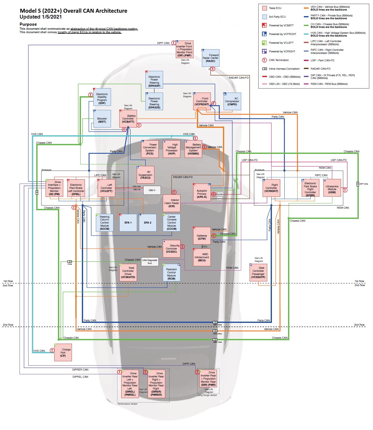
CAN Network Topology Diagram -
LIN.
- Used when high bandwidth or low latency are not required by an ECU.
- For a diagram of the LIN network topology on 2021+ Model S, click the image below for full view:
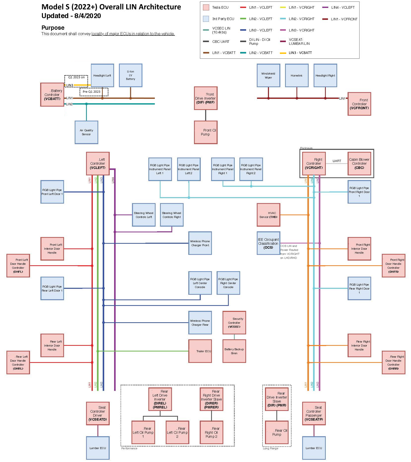
LIN Network Topology Diagram -
Video (coaxial).
Bus Mappinglink
2021+ Model S CAN bus networks are mapped to different ID numbers depending on where they connect to the microcontroller within the gateway.
| Bus ID | Bus Name |
|---|---|
| 2 | Party |
| 6 | Chassis |
| 7 | Vehicle |
CANlink
Overviewlink
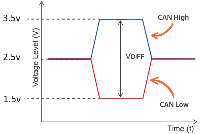
A controller area network (CAN) is a durable low-cost communication standard designed to allow any device on the network to communicate with any other device without the need for a host computer. An ECU on a CAN network is connected by 2 signal carrying wires (CAN HIGH, CAN LOW) with each wire carrying a complementary signal waveform used to signify if the signal being transmitted is a logical 1, or 0.
Transmitting and Receiving Datalink
First, a device connected to an ECU (such as a sensor) detects a value. This value is then stored in the microcontroller input memory on the ECU. If this value is also required for another ECU connected to the network, it will be sent over the CAN-Bus. Before this value can be sent, it is first copied to the transmit memory of the ECU.From there, the information goes to the transmit mailbox of the CAN module. If a current value is located in the transmit mailbox, it is indicated by the transmit flag (flag is raised). Once the message is sent to the CAN module, it then checks via the receive (Rx) line whether the bus is active (i.e. whether information is in the process of being exchanged on the network). If necessary, the message waits until the bus is free before sending over the bus. All stations connected to the bus then receive the message as it travels over the receive (Rx) lines to the receive areas of each of the CAN modules. All connected stations receive the message sent by the sensor, and using the Cyclic Redundancy Check (CRC) checksum, they detect whether any errors have occurred in transmission. When a message is sent, a checksum is generated from all the bits and is included in the transmission. The receivers all calculate the checksum from all the bits received using the same protocol. Once the received checksum is compared with the calculated checksum and no errors are found, all the stations send an acknowledgement to the transmitter. Finally, the correctly received message goes to the acceptance section of the associated CAN modules. From there, a decision is made whether the message is necessary for the function of the related control unit. If needed, the message is placed in the receive mailbox; otherwise, it is discarded.
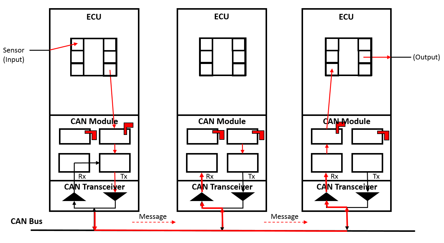 |
|---|
| CAN-Bus transmitting and receiving data 1. CAN transceiver - The transceiver is a transmitter and receiver amplifier which converts the serial bit stream (logic level) of the CAN module into voltage values and vice versa. 2. CAN module - The CAN module is what controls the data transfer process for CAN messages and is divided into two sections, the receive section and the send section. The CAN module is connected to the control unit via a receive mailbox or the send mailbox which correspond to memory locations on the microcontroller chip. 3. ECU - The ECU is the device that is receiving and processing signals from things such as sensors and actuators and is the top-level device in the stack (for example: the ESP, iBooster, EPB, etc.). |
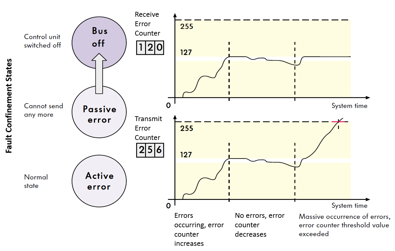
Error Managementlink
Since each message transmitted on the bus is received by each node on the bus, each node can check the validity of all the messages and post an error on the bus if a message is not valid. The tracking of these transmit (Tx) and receive (Rx) errors is how a CAN-Bus manages communication errors on the network. Using the broadcast process described in the section above, any device connected to the network that detects an error immediately notifies all other devices on the network by sending an error message called an "error frame," and the current message is then rejected by all devices on the network. This is then followed by an automatic repeat of the last transmission. If transmission continues to repeat due to continuously detected errors, an integrated error counter on each station will increase their counters to track the error. If the preset threshold value for the error limit is exceeded (equivalent to 32 repeat transmissions) the affected ECU is informed, and the CAN-Bus is switched off.
 |
|---|
| CAN-Bus error counters |
Troubleshooting Issueslink
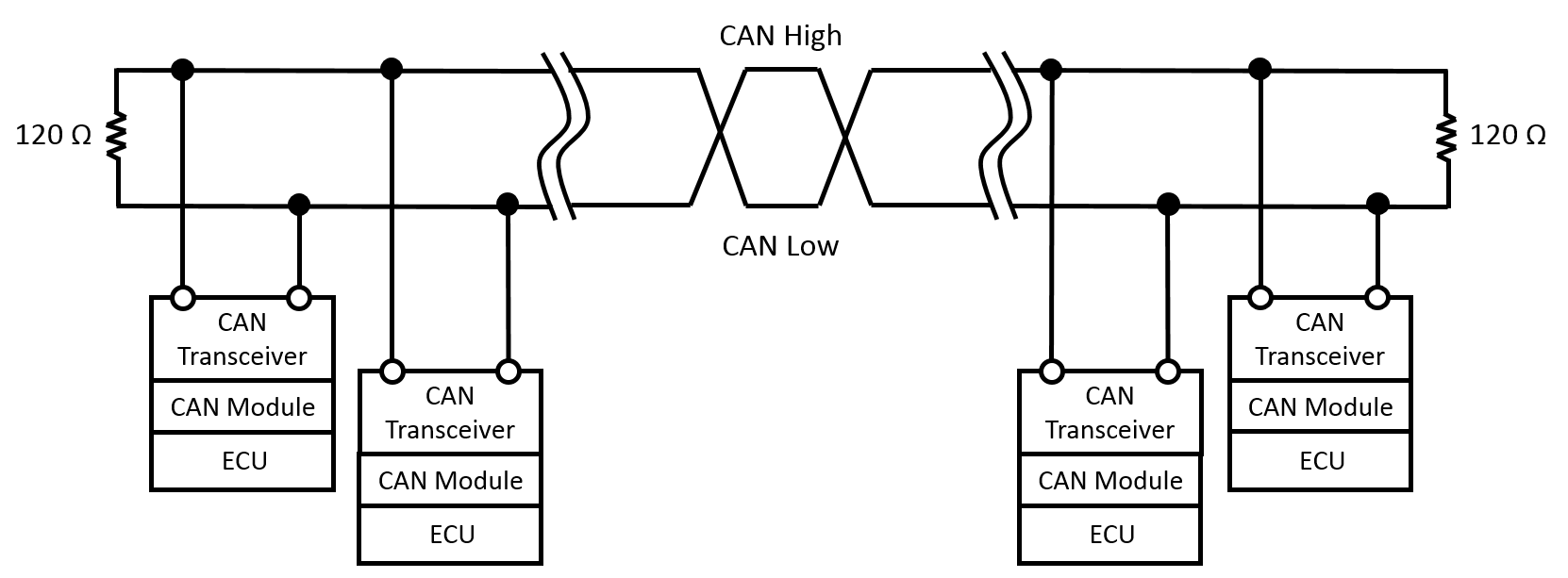
Step 1: Measure the resistance on the bus
The most common CAN-Bus issue is either too much or too little termination resistance. In a low-speed CAN network, each device connected to the bus typically has a 120Ω (ohm) resistor. In a high-speed CAN network (which is what Tesla uses), only the ends of the main loops have a 120Ω resistor. If the bus only has 2 resistors, the measured resistance between CAN-H and CAN-L will be 60Ω, which is because there are two 120Ω resistors connected in parallel. Conversely, if the bus has 3 120Ω resistors in the main loop, 40Ω will be measured, and with 4 resistors, 30Ω will be measured.
 |
|---|
| CAN-Bus |
Tip
The CAN-Bus must be powered down in order to retrieve accurate resistance measurements.
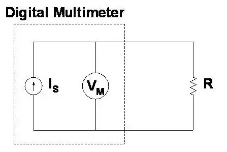
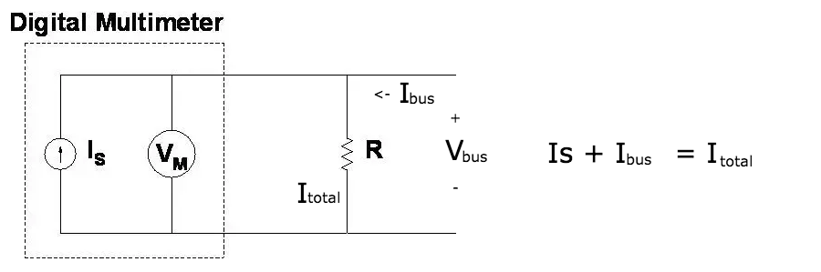
The reason the resistance measurement requires the CAN-Bus to be powered down is due to the way a Digital Multi-Meter (DMM) measures resistance. A DMM uses a constant current source to drive a known and fixed amount of current through the resistor that is being measured. In parallel, the voltage drop across the resistor is measured. The resistance is then calculated using Ohm's law, V= I÷*R, solving for R. If there is another voltage source applied to the resistor, there will be an unknown current from the bus going through the resistor, changing the voltage drop and rendering the measurement by the DMM completely invalid.
 |
|---|
| Desired operation |
 |
|---|
| Incorrect measurement |
Step 2: Measure the voltages
The voltage on a CAN-High wire usually fluctuates between 2.5V and 3.5V while the CAN-Low wire usually fluctuates between 2.5V and 1.5V. The easiest way to see these voltage fluctuations is with a pico-scope, but if a pico-scope is not available, measure the average voltage directly with a multi-meter. Around 2.2V for CAN-Low and 2.7V for CAN-High will be measured.
 |
|---|
| CAN-Bus voltages |
Step 3: Check CAN-Bus load
There are no clear-cut rules for what the max bus load should be, but in general, once the bus load increases beyond 70 percent, there's a possibility of data loss or communication errors.
Local Interconnect Network (LIN)link
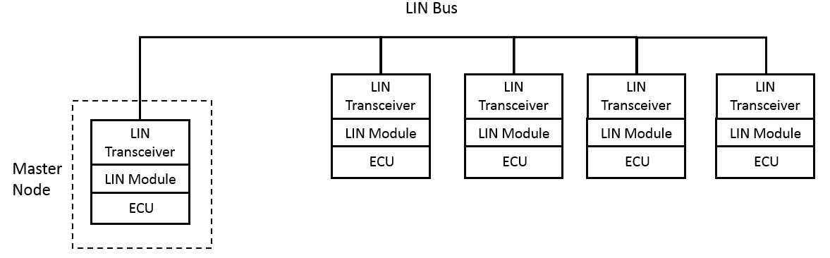
A local interconnect network (LIN) is a low-cost alternative to CAN if speed or fault tolerance are not critical. Each ECU on a LIN is connected to master node with a maximum number of 16 nodes being connected to one master. Unlike CAN, devices on a LIN network are connected by one signal-carrying wire instead of two and operating at LV bus voltage instead of 5V like CAN. If a LIN bus is connected to a CAN bus, it is usually connected via a master LIN node.
 |
|---|
| LIN-Bus |