2021+ Model X Thermal Managementlink
Last updated: January 07, 2025
Vehicle Thermal Systemlink
Heat Pump Basicslink
A heat pump transfers energy from a low temperature level to a higher temperature level using refrigerant as the energy transfer medium. Similar to an air conditioning system, a heat pump uses the following 4 stages of the basic refrigerant cycle:
- Compression via Compressor
- Heat Rejection via Condenser
- Expansion via Expansion Valve
- Heat Absorption via Evaporator
A heat pump uses a compressor to compress the refrigerant to a higher pressure / temperature and then circulate it to the condenser where it condenses and releases heat. Refrigerant then drops in pressure / temperature through the expansion valve (EXV) before vaporizing by absorbing heat in the evaporator. The refrigerant then returns back to the compressor to repeat the cycle.
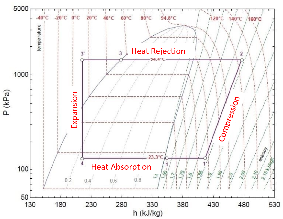
Shown below is a detailed description of the refrigerant cycle and the related 4 stages:
 |
|---|
| Diagram of the refrigerant cycle with 4 stages noted |
-
Compression Phase (1’ ➔ 2)
The AC compressor compresses the refrigerant, resulting in an increased pressure and temperature. Refrigerant is in 100% vapor state during the whole compression stage.
-
Heat Rejection Phase (2 ➔ 3 ➔ 3’)
In the condenser(s), heat is rejected and refrigerant temperature decreases while pressure remains high.
When starting to cool the refrigerant (starting point 2 in the diagram), it's in 100% vapor state until it reaches the parabolic-shaped area (this is about halfway of points 2 and 3 following the 54.4 °C dotted temperature line). The area to the right of this line is the vapor area. From this point going to the left, refrigerant condenses to 100% liquid until point 3 has been reached.
In the area to the left of point 3, refrigerant is in 100% liquid state.
The coexistence area lies within the parabolic shape. Refrigerant transitions from 100% vapor, going to the left through the coexistence phase (=gas/liquid mixture) at a fixed temperature into 100% liquid state. Normally, refrigerant always transitions from vapor to liquid (and vice versa) when going through the area of coexistence. There is only one exception, which is the 94.8°C temperature line touching the top of the coexistence area. Under this combination of pressure and temperature, refrigerant transitions from 100% vapor into 100% liquid all at once. This is the refrigerant's critical point.
When refrigerant is in its coexistence phase, the temperature does not change due to physical characteristics. Temperature only changes if refrigerant is in 100% vapor state or 100% liquid state.
Specifically in the 3 ➔ 3’ portion, the condenser(s) cool down refrigerant past the point of 100% liquid phase. This temperature drop is the subcool temperature. This subcool temperature represents the overcapacity of the condenser(s) that is needed to make sure that refrigerant passes the 100% liquid phase point.
-
Expansion Phase (3’ ➔ 4)
While passing through the expansion valve (EXV), refrigerant drops in pressure and temperature when expanding and transitions from 100% liquid into vapor/liquid mixture (coexistence).
-
Heat Absorption Phase (4 ➔ 1 ➔ 1’)
In the evaporator, heat is absorbed by the refrigerant and cools the cabin air when it flows through the cabin’s evaporator. In the coexistence phase (point 4 ➔ 1), heat is absorbed at a constant temperature until the 100% gas phase has been reached (point 1).
-
Evaporation Phase (1 ➔ 1’)
Evaporator heats up refrigerant past the 100% vapor phase point. This temperature increase is the superheat temperature. The superheat temperature represents the overcapacity of the evaporator needed to make sure the refrigerant passes the 100% vapor phase point.
Difference Between Heat Pump and Standard Air Conditioning Systemslink
Unlike a standard air conditioning system, a heat pump can be used for both heating and cooling. Although both heat pumps and air conditioning systems use the same refrigerant cycle as described previously, the heat pump system uses a series of valves to control the direction of refrigerant flow in the system. For example, the Tesla heat pump system is able to heat or cool the vehicle cabin by directing refrigerant flow to either the cabin evaporator or cabin condenser. These valves and refrigerant flow will be described in detail later in the document.
Advantages of Heat Pump for EVslink
The Tesla heat pump system allows the vehicle to heat and cool the cabin and HV battery in a very efficient way. For example, the heat pump is able to heat the cabin by using heat energy from ambient air or heat energy from the HV battery (called Scavenge). Likewise, the heat pump is also able to heat the HV battery by using heat energy from ambient air or heat energy from the cabin evaporator. As a result, in both cabin and HV battery heating mode, the heat pump can be more efficient than the following electric vehicle heat sources:
- PTC cabin heater
- Battery coolant heater
- Drive unit coolant heater
Due to the heat pump's increased efficiency, the following advantages are possible:
- Reduced energy consumption / range increase.
- Significant increase in cabin heating power.
- Cold weather supercharge time reduction.
Coefficient of Performance (COP)link
The Tesla heat pump system operates in various modes defined by the Coefficient of Performance (COP). In general, heating performance is measured by COP rather than efficiency. The higher the COP of the system, the greater the heating performance with respect to the energy input.
Note
Efficiency (η) cannot exceed 100% according to its definition (“free” energy may not be added as energy input). This is the reason why COP is used; it is expressed as a dimensionless factor (not as a percentage).
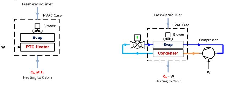
The definition of Coefficient of Performance is COP=Qh/W=(Energy output)/(Energy input).
For example, a Positive Temperature Coefficient (PTC) heater has a (theoretical) COP=Qh/W=1. This means, the energy to heat up the cabin (Qh) = energy from the PTC heater (W), supplied by the HV battery.
 |
|---|
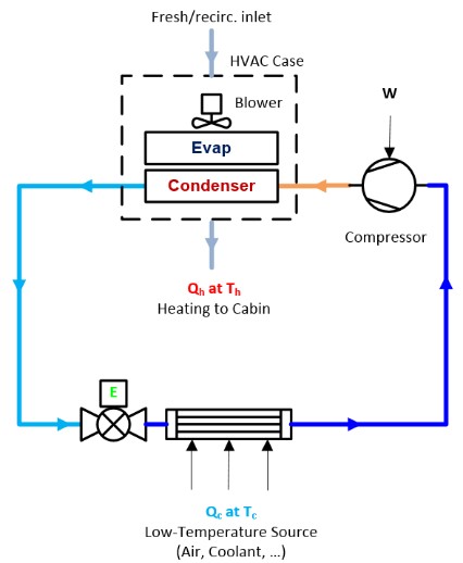
In case of a heat pump (Qh=W+Qc):
Heat entering the cabin (Qh) equals electrical energy from the compressor (W) + free energy from the ambient air (Qc). This is why the heat pump is very effective for heating.
A heat pump (COP=Qh/W=(W+Qc)/W≥1):
The COP for a heat pump normally varies between 1 and ≈5 depending on ambient temperature. If, for example COP=3, the cabin is heated (Qh) with heat pump electrical power (W) = 100% + Qc (energy for free from ambient air or coolant) = 200%, in total 300% = COP 3.
 |
|---|
COP Modeslink
The Tesla heat pump system operates in different COP modes, varying from a very efficient COP ≈ 5.6 to a PTC heater-like efficiency of COP=1. These COP modes are expressed in a range from COP High, COP Blend, and COP 1. The modes change depending on:
- Ambient temperature
- HV battery temperature
- Coolant temperature
- Whether cooling or heating (cabin or HV battery) is requested.
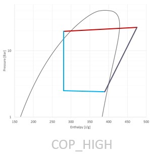
COP Highlink
 |
|---|
COP High mode is used when battery temperature is between 15°C to 50°C range.This is the most efficient and preferred mode that the heat pump can run in, COP up to ≈5.6 in best scenario. In this mode, the AC compressor is running at its lowest speed.
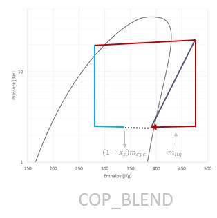
COP Blendlink
 |
|---|
COP Blend mode is used when battery temp is between +10°C to +15°C range.
The goal is to use a controlled amount of heat from the powertrain/battery to heat the cabin. In COP Blend mode, COP value is between ≈5.6 and 1, refrigerant under temperature and pressure is entering the mister (see refrigerant loop in the next paragraph) and supplements chiller heat from ambient or powertrain/battery with electrical power used by the heat pump.
This operation mode allows the system to act like a conventional heat pump and an electrical heater at the same time. COP Blend is there to get a reasonably good COP without over-cooling the battery (e.g. the naturally produced heat from driving around almost funds the cabin heating needs, but not fully).
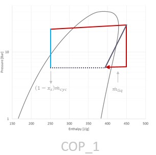
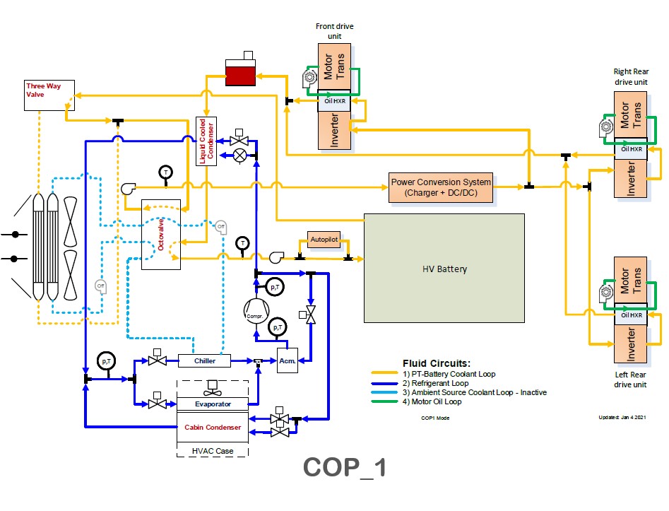
COP 1link
 |
|---|
COP 1 mode is used when the battery temperature is between -40°C to +10°C range. COP 1 is an extreme version of COP Blend mode where the heat pump acts as a PTC heater. This mode is the least efficient mode and the heat pump is running at COP = 1.
In this mode, the system quickly heats up refrigerant, transferring the electrical power consumed by the compressor to the cabin. When the system is running in COP 1 mode, the compressor is running at high compressor speeds at start up. This requires the EXV.recirc to actuate in such a way (along with the other valves) to regulate the suction and discharge pressures. When there is enough heat in the system, it changes over to COP Blend mode.
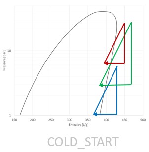
Cold Startlink
 |
|---|
Cold Start mode is used in very cold circumstances where neither the ambient air nor the HV battery can provide enough energy. In this mode, refrigerant is heated up in a similar way as COP 1, but is flowing through the compressor, EXV.recirc, mister, and accumulator by closing all other expansion valves.
This process is shown in the right image, triangles going from blue to green to red and then going into COP 1 mode, building up pressure and temperature into the system.
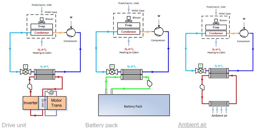
Heat Pump Sourceslink
The Tesla heat pump relies on 3 heat sources:
- Drive unit's rejected heat scavenging.
- HV battery thermal mass funding energy.
- Ambient air (through the radiator).
All 3 of these heat sources require heat transfer to the refrigerant using the vehicle coolant loop.
 |
|---|
Thermal Schematic Overviewlink
Coolant Looplink
In order to transfer heat between the vehicle coolant loop and refrigerant, the coolant loop needs to be in the correct position.
Note
2021+ Model X is available in Long Range or Plaid configurations. The coolant loop configurations are similar for both, except Plaid has 2 rear drive units connected in parallel with the front drive unit, while Long Range only has 1 rear drive unit connected in series with the front drive unit.
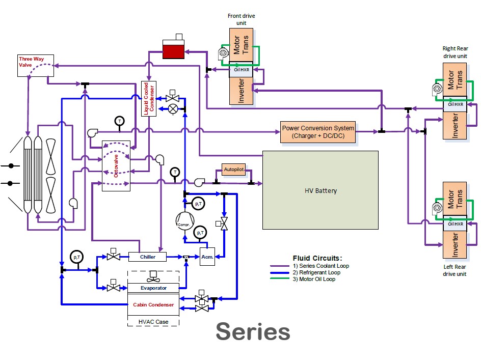
Pictured below is the 2021+ Model X Plaid configuration and the 5 possible positions the coolant loop can be in:
-
Series
Series mode connects the HV battery coolant loop to the powertrain coolant loop for heat rejection from both loops via both radiators to ambient.
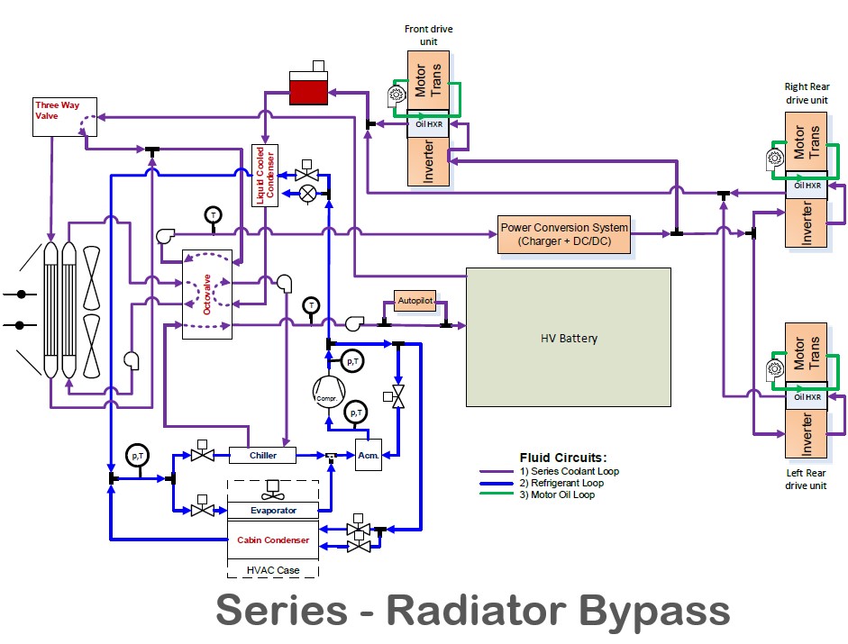
-
Series – Radiator Bypass
Series – Radiator Bypass mode connects the HV battery coolant loop to the powertrain coolant loop for heat rejection from both loops via chiller for heat pump cabin heating.
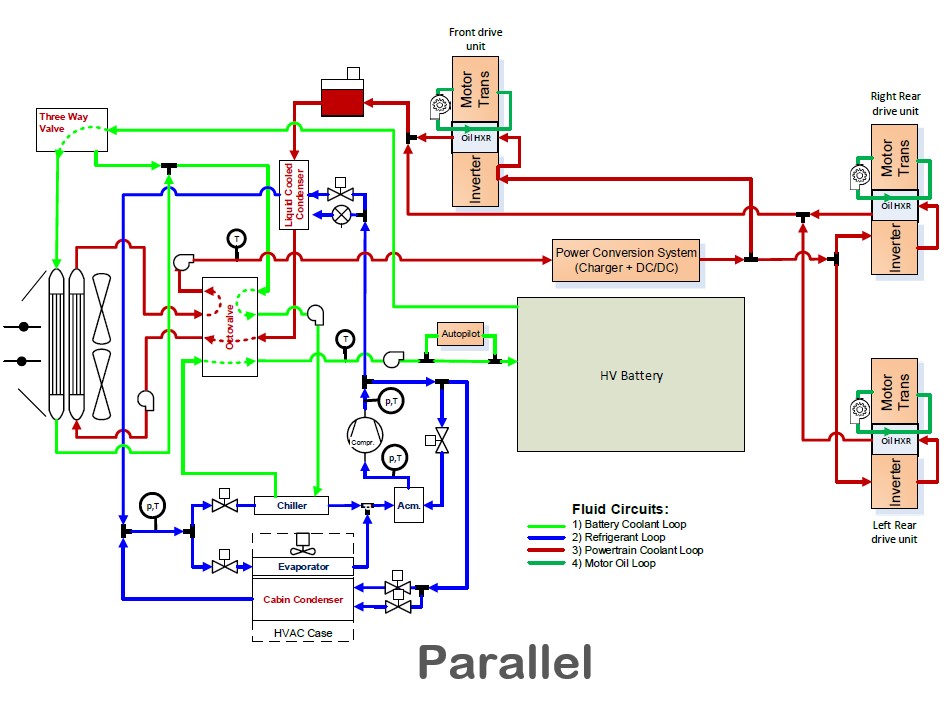
-
Parallel
Parallel mode separates the HV battery and powertrain coolant loops. This mode allows separate heat rejection from HV battery and powertrain to their respective separate radiators.
Parallel mode also allows heat rejection from HV battery via chiller for heat pump cabin heating.
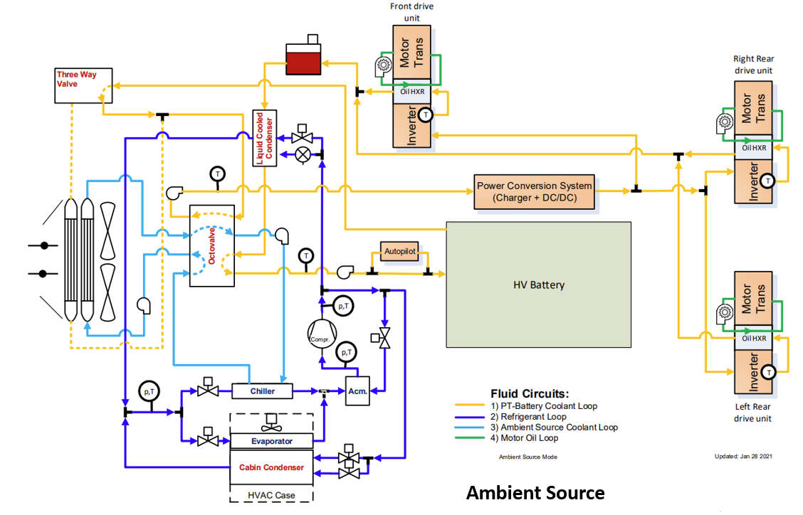
-
Ambient Source
Ambient Source mode allows heat from ambient air via the powertrain radiator to be rejected to the chiller for heat pump cabin heating. This mode also connects the HV battery coolant loop to the powertrain coolant loop, bypassing the battery radiator, for HV battery heating.
-
COP 1
COP 1 mode turns OFF both chiller pumps, thus allowing no heat from ambient air via the powertrain radiator to be rejected to the chiller. Instead, the A/C compressor uses the internal mister loop to generate heat for cabin heating.
COP 1 mode also connects the HV battery coolant loop to the powertrain coolant loop, bypassing the battery radiator, for HV battery heating (same as Ambient Source mode).
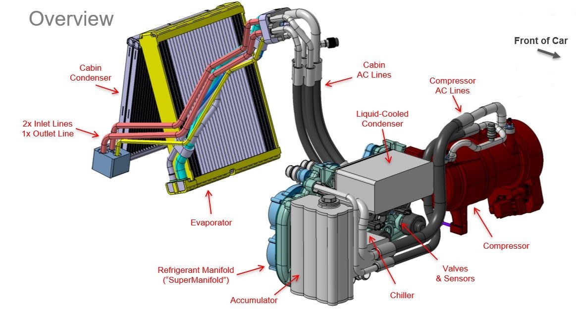
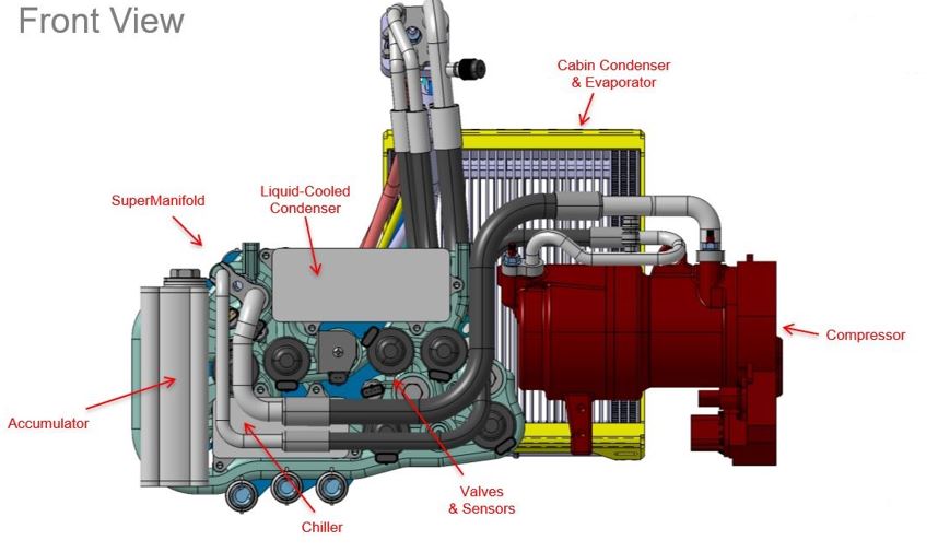
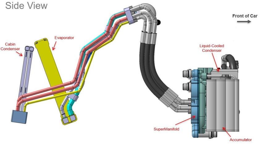
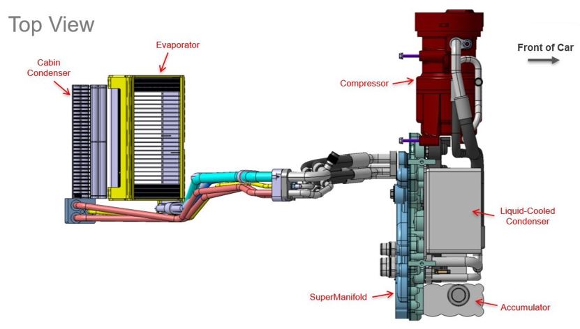
Overview of Heat Pump System Componentslink
The following diagrams show the layout of the Tesla heat pump system and the related components. Each component is described in further detail.
 |
|---|
 |
|---|
 |
|---|
 |
|---|
 |
|---|
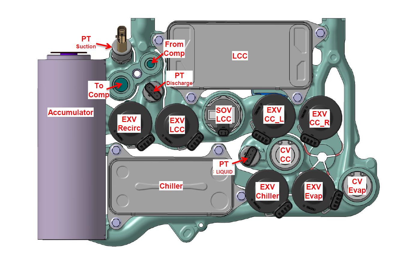
| Front view of the supermanifold |
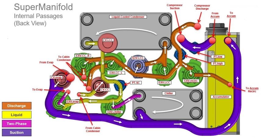 |
|---|
| Back view of the supermanifold's internal passages |
 |
|---|
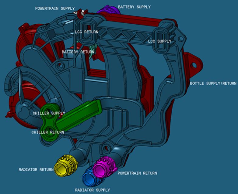
| Back view of the supermanifold |
Components, Abbreviations, and Their Functionslink
Liquid Cooled Condenser (LCC)link
The Liquid Cooled Condenser (LCC) rejects heat from refrigerant to coolant. It is used for evaporator cabin cooling, chiller battery cooling, or ambient source battery heating. The LCC is mounted on the thermal bar.
Cabin Condenser (CC)link
The Cabin Condenser (CC) rejects heat from refrigerant to cabin air.
The PTC heater (from a HVAC/thermal system with PTC heater) exists as a single unit, heating air for both sides of the vehicle up to the same temperature. In case the driver and passenger selected different temperature settings, blend valves mix colder air with warm air from the PTC heater in order to reach the requested (different) temperatures for driver and passenger sides.
In the heat pump layout, the left and right cabin condensers reject the exact amount of heat needed for split temperature settings by controlled by the left and right cabin condenser electronic expansion valves (EXV.CC_L and EXV.CC_R). Therefore, blend valves are not needed.
Evaporatorlink
The evaporator rejects cold energy to cool cabin air. In particular conditions, the evaporator also runs at the same time as the cabin condensers (heating up cabin air) to control humidity and temperature.
Chillerlink
The chiller rejects cold energy from refrigerant to coolant circuit to cool the HV battery, Power Conversion System (PCS), autopilot ECU, and drive units.
Accumulatorlink
The accumulator controls the amount of liquid refrigerant and vapor quality that enters the compressor. It also manages the oil's return to the compressor. The accumulator houses two filters, a desiccant bag, and stores inactive refrigerant charge.
Misterlink
The mister is similar to a venturi principle. It blends vapor refrigerant (coming from the AC compressor when the EXV.recirc is opened) with liquid refrigerant in the accumulator.
Octovalvelink
The Octovalve is a rotary valve with eight ports to control the coolant flow paths in coolant system. The connection between the internal coolant channels and the external coolant channels varies when the Octovalve is in different positions. This allows the cooling system to operate in series, series (radiator bypass), parallel, or ambient source modes.
Octovalve consists of three components: the motor and gearbox assembly, the valve core, and the valve seat. The valve core rotates to specific angles which correspond to specific positions for the Octovalve.
Electronic Expansion Valveslink
In an expansion valve, refrigerant drops in pressure and temperature when expanding and transitions from 100% liquid into vapor/liquid mixture (coexistence). The supermanifold has 6 expansion valves on it, described in the sections below.
| Valve Acronym | Valve Name |
|---|---|
| EXV.LCC | Liquid cooled condenser expansion valve |
| EXV.CC_L | Left cabin condenser expansion valve |
| EXV.CC_R | Right cabin condenser expansion valve |
| EXV.chiller | Chiller expansion valve |
| EXV.evap | Evaporator expansion valve |
| EXV.recirc | Recirculation expansion valve |
EXV.LCClink
The electronic expansion valve liquid-cooled condenser (EXV.LCC) controls refrigerant flow to the liquid-cooled condenser. Refrigerant is sometimes sent to the LCC when a small amount of cabin reheat is required, but not all the hot refrigerant. During cabin reheat, both the cabin evaporator and cabin condenser are in use and the evaporator heat gain can be greater than the condenser heat rejection. As a result, the LCC is used to reject the remainder of the evaporator and compressor heat to ambient.
EXV.chillerlink
The chiller expansion valve (EXV.chiller) controls refrigerant flow to chiller. EXV.chiller is actuated based on signals from the pressure temperature subcool (PT SC) sensor on the liquid pressure line between condensers and EXV.chiller.
EXV.evaplink
The evaporator expansion valve (EXV.evap) controls refrigerant flow to evaporator.EXV.evap is actuated based on signals from the pressure temperature subcool (PT SC) sensor on the liquid pressure line between condensers and EXV.evap.
EXV.recirclink
The recirculation expansion valve connects the high side of the refrigeration cycle to the mister and controls heat pump operation in COP Blend and COP 1 operating modes. The EXV.recirc valve controls how the heat pump operates in COP Blend and COP 1 operating states.
In COP Blend, the goal is to use a controlled amount of heat from the powertrain/battery to heat the cabin. When the EXV.recirc opens, it essentially short circuits the cycle in a controlled way, supplementing chiller heat from ambient or powertrain with electrical power. This blend mode allows the cycle to act like a conventional heat pump and an electrical heater at the same time, depending on the state of the thermal system loop and HVAC needs.
COP 1 is the extreme version of this mode. In this mode, the compressor is operated “as a heater” and is able to transfer the electrical power consumed by the compressor to the cabin. This requires the EXV.recirc (along with the other valves) to actuate in such a way to regulate the suction and discharge pressures.
Check Valveslink
All of the check valves are mechanically operated. See the sections below for a description of how each check valve functions.
| Valve Acronym | Valve Name |
|---|---|
| CV.LCC | Liquid cooled condenser check valve |
| CV.CC | Cabin condenser check valve |
| CV.evap | Evaporator check valve |
| SOV.LCC | Liquid cooled condenser shut off valve |
CV.CClink
The cabin condenser check (CV.CC) valve prevents refrigerant from entering heat exchangers when it is off. This valve stops hot refrigerant from entering the cabin condensers (and thus heating it) when all the high side energy should be rejected to ambient.
CV.LCClink
The liquid cooled condenser check valve (CV.LCC) has the same functionality as CV.CC. In addition, it helps avoid too much refrigerant charge from being trapped in the LCC when inactive (like cold weather).
CV.evaplink
The evaporator check valve (CV.evap) prevents refrigerant from entering the evaporator when not in use.
SOV.LCClink
The liquid cooled condenser shut off valve (SOV.LCC) is a large bore valve that is mounted in parallel with EXV.LCC. This valve protects the system in case of overpressure.
Refrigerant Pressure & Temp (PT) Sensorslink
PT Discharge Sensorlink
The PT discharge sensor (PT high) measures the refrigerant discharge pressure and temperature. It is the true A/C compressor discharge and protects the compressor from over-pressure/over-temperature.
PT Subcool Sensorlink
The PT subcool (SC) sensor measures the SC of the refrigerant leaving the LCC and entering the chiller and evaporator. This sensor is used to control the cycle, thus providing adequate subcooled liquid refrigerant to the chiller and evaporator for maximum cooling.
PT Suction Sensor (PT low)link
The PT suction sensor (PT low) measures the refrigerant suction pressure and temperature. It is used for COP 1 and detecting abnormal conditions/low refrigerant charge.
Thermal System Operationlink
State Machine Vectorlink
The cabin air can be purely cooled or heated, without the need for dehumidification. See Cabin State (off, heating, cooling) in the chart below. Pure heating can only be done if the relative humidity (RH) of the air is in the right range already. If the RH is too high to be in the comfortable range, it is reduced by cooling down the cabin air by letting it flow through the evaporator beyond the point of condensation, which reduces the absolute water mass in the air. The lower the evaporator target, the lower absolute water mass will be. Air needs to be reheated after the evaporator to create the right RH-temperature combination. This is represented by the Reheat State (off, heating dominant, or cooling dominant state).
What blend mode the heat pump refrigerant cycle is in depends on battery and ambient temperatures. The goal is to let the system run at the highest COP possible in order to get the highest efficiency and the longest range.
| Component | ON / OFF | Heating state | Cooling state |
|---|---|---|---|
| Cabin | OFF | Heating | Cooling |
| Reheat | OFF | Heating Dominant | Cooling Dominant |
| Battery | OFF | Heating | Cooling |
| Blend Mode | OFF (COP High) | Partial (COP Blend) | COP 1 |
| Ambient Source | OFF | ON | - |
| Octovalve | Series | Parallel | Ambient Source |
| Radiator Bypass | OFF | ON | - |
When ambient temperature and HV battery temperature are low and the cabin needs to be heated, Ambient source or Scavenge (getting heat from the HV battery through the coolant loop) cannot be used. In order to generate heat for the cabin, the system can be run in lower COP modes or even at COP=1. In this situation, the compressor basically runs with the efficiency of a PTC heater.
The state machine vector shows the combination of component states for every operating mode.
Most Common Modeslink
The most common modes (out of 30 possible modes in total) are shown below.
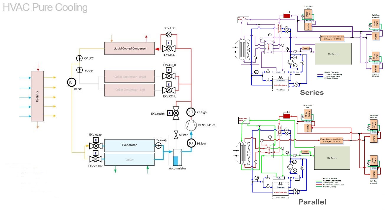
Example 1 - HVAC Pure Coolinglink
When air humidity is in its correct range, reheating is not needed and only the evaporator is used to condition the cabin air. The compressor, liquid cooled condenser (LCC), and evaporator are in use at the refrigerant side. Refrigerant heat is rejected in the LCC and heats up the coolant to heat the HV battery when in Series or rejects heat through the radiator when in Parallel.
In these circumstances, usually ambient temperature is high enough for the refrigerant cycle to run in COP_high mode, so the system is running in the highest efficient mode.
| Cabin | Cooling |
|---|---|
| Reheat | OFF |
| Battery | OFF |
| Blend Mode | OFF (COP High) |
| Ambient Source | OFF |
| Octovalve | Parallel or Series |
| Radiator Bypass | ON or OFF |
 |
|---|
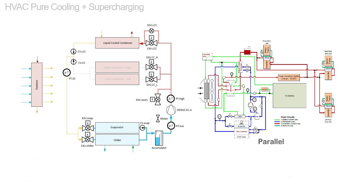
Example 2 - HVAC Pure Cooling + Supercharginglink
Same situation for the cabin cooling applies here: when air humidity is in its correct range, reheating is not needed and only the evaporator is used to condition the cabin air.
In the situation where the HV battery needs cooling as well, the compressor, liquid cooled condenser (LCC), evaporator, and the chiller are in use at the refrigerant side.
Refrigerant heat is rejected in the LCC, heats up the coolant, and rejects that heat through the radiator. In this mode, the system runs in Parallel.
In these circumstances, usually ambient temperature is high enough for the refrigerant cycle to run in COP_high mode, so the system is running in the highest efficient mode.
| Cabin | Cooling |
|---|---|
| Reheat | OFF |
| Battery | Cooling |
| Blend Mode | OFF (COP High) |
| Ambient Source | OFF |
| Octovalve | Parallel |
| Radiator Bypass | OFF |
 |
|---|
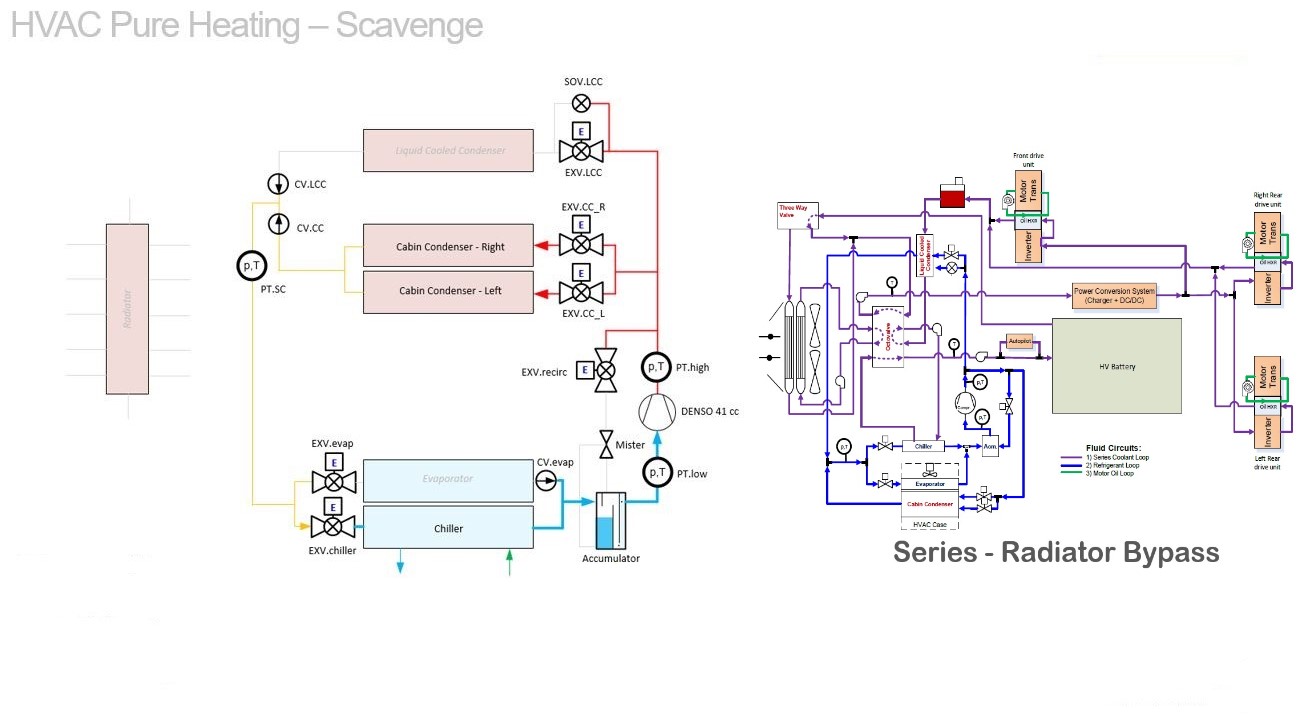
Example 3 - HVAC Pure Heating + Scavengelink
During pure cabin heating, only the cabin condensers are used to heat up the cabin air. At the refrigerant side, the compressor, cabin condensers, and chiller are in use.
Refrigerant heat is rejected in both cabin condensers and the HV battery thermal mass is being used (Scavenge) to transfer energy into the refrigerant circuit through the chiller.
Ambient temperatures are low and sufficient to heat up the system, therefore it is running in Series and the radiator is bypassed. The system is able to run in COP_high due in these conditions.
| Cabin | Heating |
|---|---|
| Reheat | OFF |
| Battery | OFF |
| Blend Mode | OFF (COP High) |
| Ambient Source | OFF |
| Octovalve | Series |
| Radiator Bypass | ON |
 |
|---|
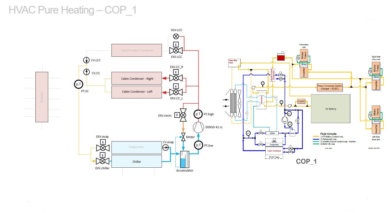
Example 4 - HVAC Pure Heating + COP 1link
During pure cabin heating, only the cabin condensers are used to heat up the cabin air.
At the refrigerant side, the compressor, cabin condensers, and mister are in use. The left pump is switched off, so there is no heat exchange with ambient air despite the Octovalve being in the Ambient Source position.
The compressor is being shorted by the mister, mixing high temperature and high pressure from the compressor itself with low pressure and low temperature coming from the chiller. This results in an increased suction temperature and pressure. This process runs in COP 1 and basically runs like a PTC heater, turning all electric power into heating refrigerant fast.
Refrigerant heat is rejected in both cabin condensers. Ambient temperatures are low, so the system is running in COP 1 mode to quickly heat up the refrigerant.
| Cabin | Heating |
|---|---|
| Reheat | OFF |
| Battery | OFF |
| Blend Mode | OFF (COP 1) |
| Ambient Source | OFF |
| Octovalve | Ambient Source |
| Radiator Bypass | ON |
 |
|---|
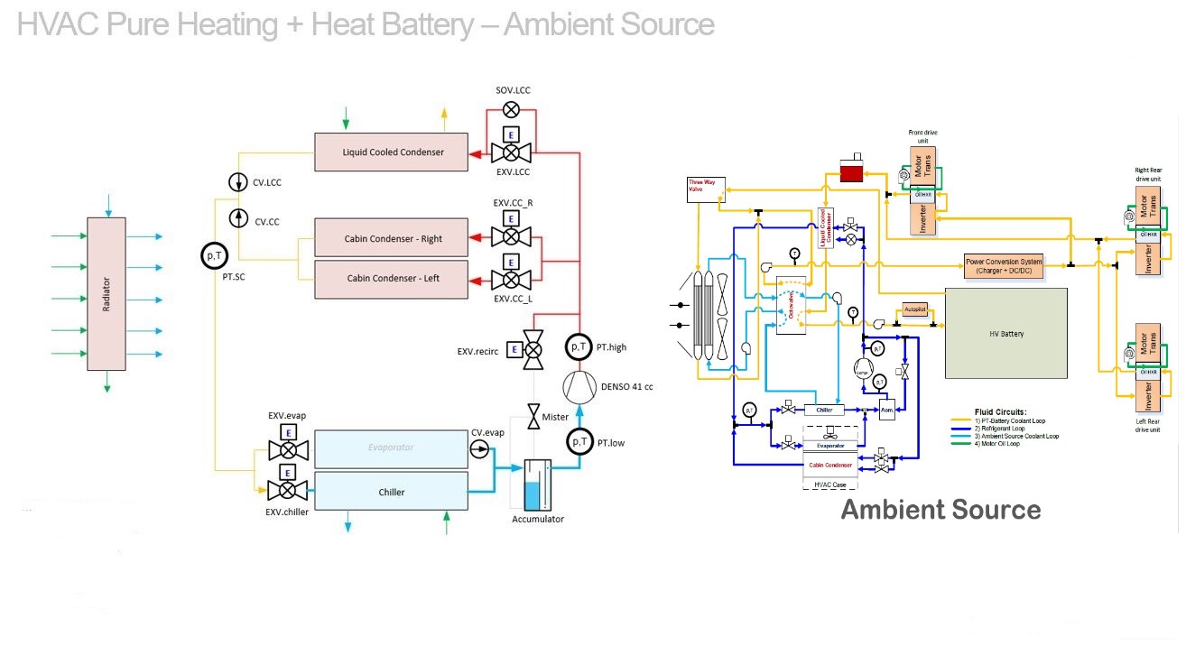
Example 5 - HVAC Pure Heating + Heat Battery + Ambient Sourcelink
Cabin condensers are used to heat up the cabin air and at HV battery side, the liquid cooled condenser (LCC) is used to heat up the coolant flow running through the battery. The coolant running through the chiller is heated up by the radiator coolant flow and is getting its energy from Ambient.
| Cabin | Heating |
|---|---|
| Reheat | OFF |
| Battery | Heating |
| Blend Mode | OFF (COP High) |
| Ambient Source | ON |
| Octovalve | Ambient Source |
| Radiator Bypass | OFF |
 |
|---|
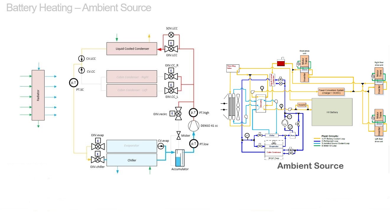
Example 6 - Heat Battery + Ambient Sourcelink
The HV battery is heated by the liquid cooled condenser (LCC). The coolant running through the chiller is heated up by the radiator coolant flow and is getting its energy from Ambient. Radiator and chiller are in Series.
| Cabin | OFF |
|---|---|
| Reheat | OFF |
| Battery | Heating |
| Blend Mode | OFF (COP High) |
| Ambient Source | ON |
| Octovalve | Ambient Source |
| Radiator Bypass | OFF |
 |
|---|
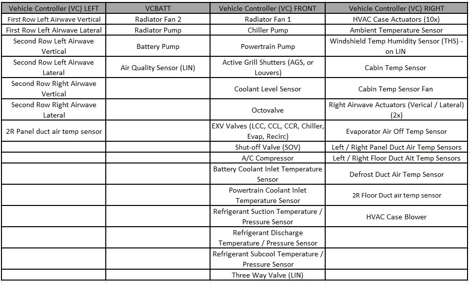
Component Communication and Controllink
 |
|---|
Coolant Propertieslink
The coolant fill for 2021+ Model X consists of G-48 coolant, which is tinted blue. The coolant is supplied from the manufacturer pre-mixed 50/50 concentration with distilled water. G-48 is a long-life coolant designed for high aluminum content powertrain systems.
Warning
Do not top off or refill the cooling system with any other type of coolant.
Coolant Pumpslink
2021+ Model X uses four coolant pumps. Two pumps are integrated into the supermanifold and the other two pumps are offboard. All pumps are serviceable items.
The coolant pumps are brushless centrifugal pumps designed to run between 9 and 16VDC. They are 3-phase pumps that consume up to 15A each when running a maximum duty cycle. The pumps do not have a built-in controller/driver and instead rely on a controller chip in the front vehicle controller (VCFRONT) or the vehicle battery controller (VCBATT) to drive the three phases of the pumps.
Coolant Temperature Sensorslink
2021+ Model X uses two coolant temperature sensors. The battery coolant inlet sensor provides the HV battery inlet coolant temperature and the powertrain inlet sensor provides powertrain inlet coolant temperature to the VCFRONT. Both of these coolant temperature sensors are the same Negative Temperature Coefficient (NTC) sensors and are serviceable items.
Active Shutterslink
2021+ Model X has an active shutter assembly that controls airflow to the cooling module. The shutter assembly is visible from the front of the vehicle.
The active shutters are motor-actuated from a single actuator and the motor is controlled via the VCFRONT.
The active shutters control the flow of ambient air through the radiator. The system is designed to keep airflow at the minimum amount necessary for cooling. Also, minimizing the airflow can be used to reduce the time for components to reach normal operating temperature.
The active shutters also minimize the vehicle’s aerodynamic drag when cooling demands are low, thus reducing the vehicle’s power requirements and increasing range. The active shutters close when the vehicle is not in Drive mode, but open if required when cooling the vehicle’s charging system during Charge mode or running the cabin HVAC in Support mode.
Radiator Fanlink
2021+ Model X uses a dual radiator fan assembly. The fan motors are maintenance-free, brushless DC (BLDC) motors. The fans are controlled by VCFRONT and VCBATT. The motors, fans, and shroud are serviced as a single assembly.
Cabin Heating, Ventilation, Air Conditioning (HVAC) Systemlink
 |
|---|
Refrigerant Systemlink
The refrigerant system is a sealed, closed-loop system filled with a refrigerant charge of either R-134a (at SOP) or R-1234yf (later) refrigerant as the heat transfer medium. A non-conductive Polyolefin Ester Oil (POE) with ND-11 specifications is added to the refrigerant to lubricate the internal components of the compressor. This oil is supplied in the compressor during manufacture. Whenever the system is discharged and/or components are replaced, refrigerant and oil must be replaced in an equivalent weight to what was removed.
Note
Specifications and capacities section for refrigerant and oil information table - See Appendix A.
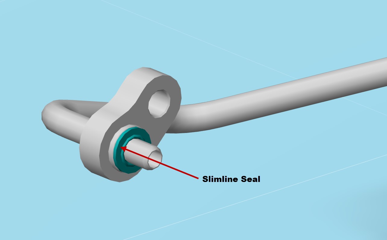
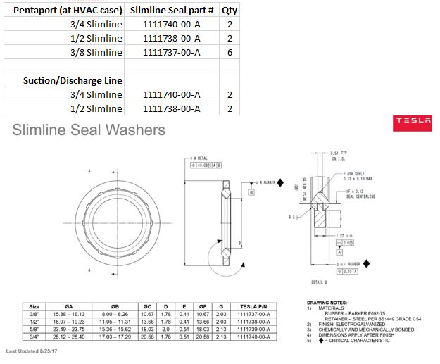
A/C Line Connection Sealslink
All A/C line connection use Slimline style seals, which are only designed for one time use. If the connection is opened, the Slimline seal should be replaced. 2021+ Model X uses three different sizes of Slimline seals throughout the A/C system.
Note
Slimline seal lookup table - See Appendix B.
 |
|---|
In-Vehicle Temperature Sensorlink
The in-vehicle temperature sensor is single printed circuit board (PCB) unit. The sensor includes an integrated fan to move air past the sensor for more accurate sensor readings. The sensor is connected directly to the VCFRONT.
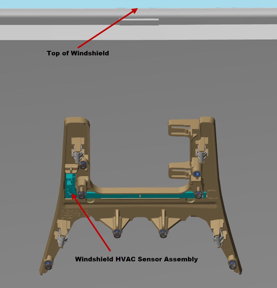
Windshield HVAC Sensor Assembly (Windshield Temperature, Humidity, Sunload)link
The windshield HVAC sensor assembly includes the windshield temperature sensor, humidity sensor, and sunload sensor. All the sensors are contained on one circuit board that is mounted to the windshield surrounding the rear view mirror. The sensors are connected directly to the VCFRONT. The VCFRONT uses the sunload information to estimate the heating effect on the vehicle from sunlight. It uses this input to maintain the desired cabin temperature as the sunload varies.
The VCFRONT also uses the humidity data from the humidity sensor for windshield fogging detection. If conditions for windshield fogging are detected, the VCFRONT attempts to reduce fogging by forcing fresh air, turning on partial Defrost mode, and turning on the air conditioning evaporator.
 |
|---|
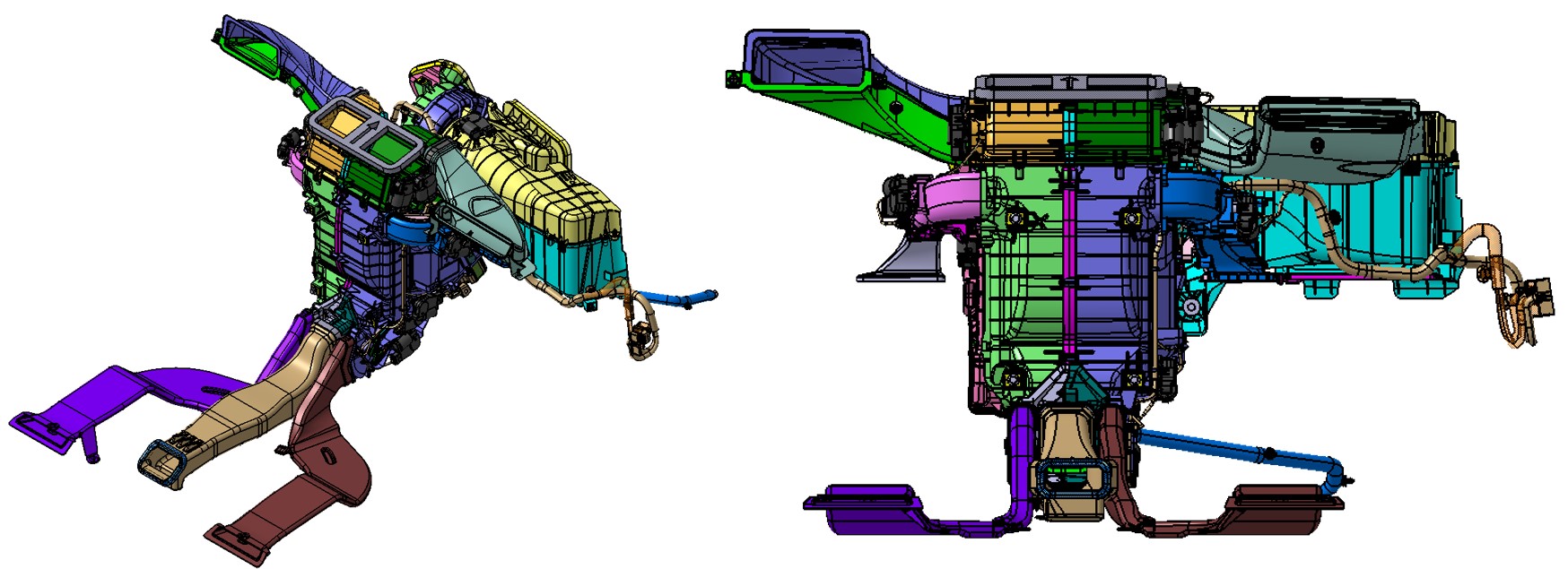
HVAC Caselink
The HVAC case is located under the instrument panel and contains the following components:
- Blower motor
- Cabin filter
- Evaporator (cools air)
- Condenser (heats air)
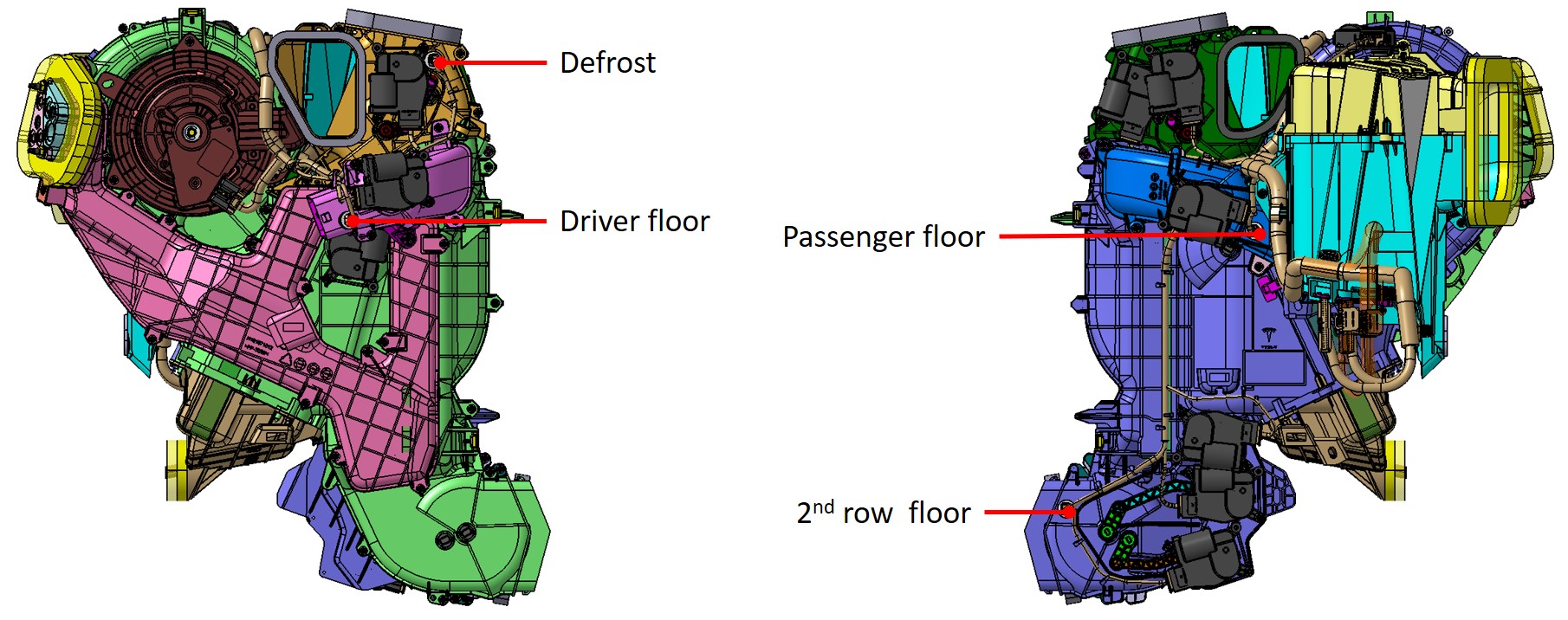
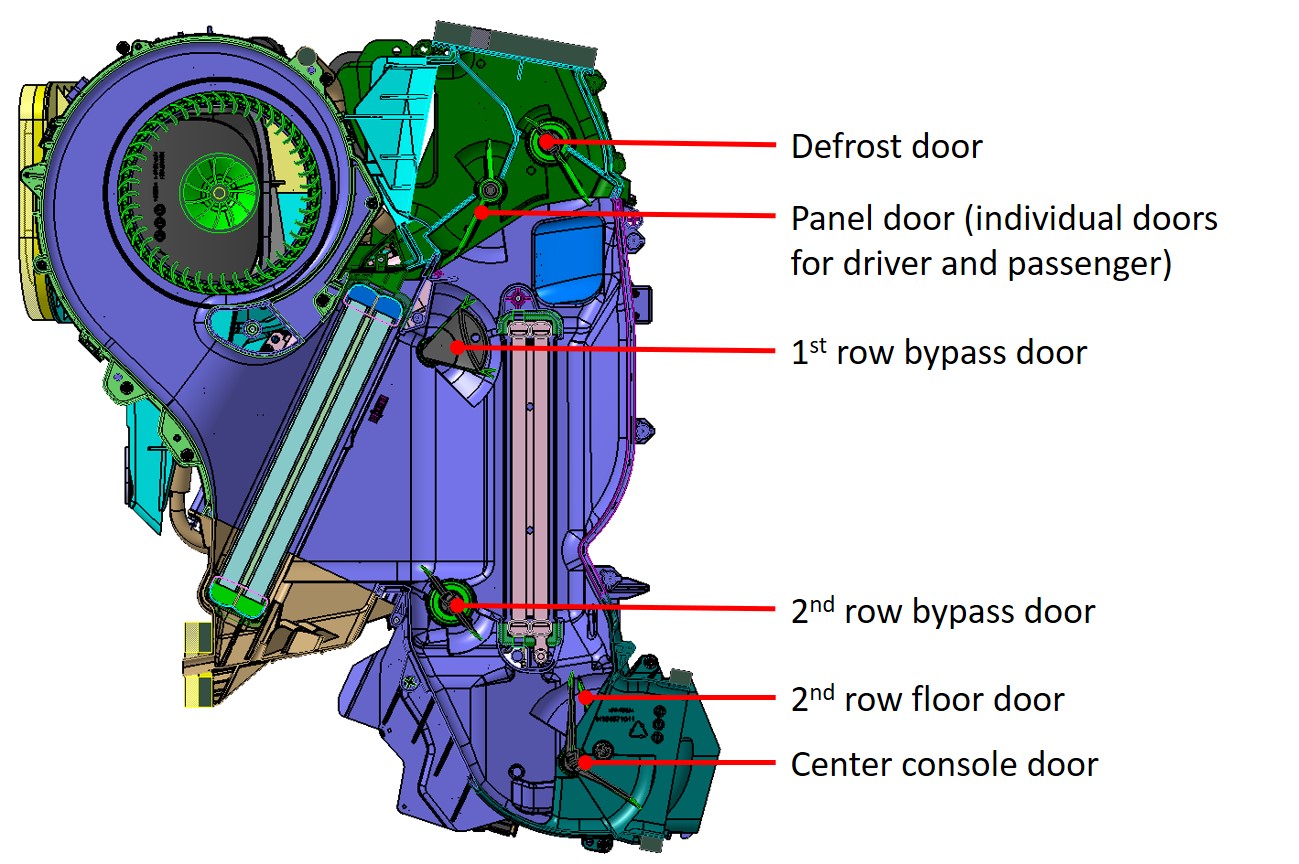
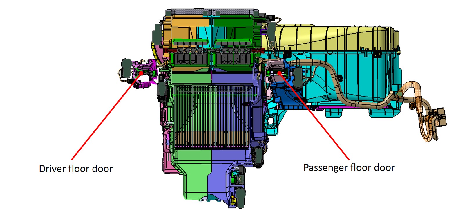
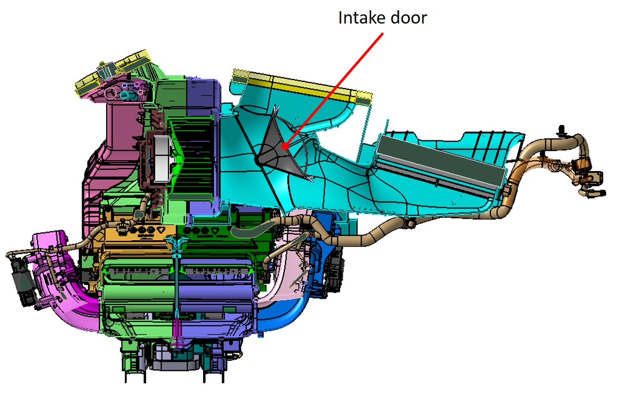
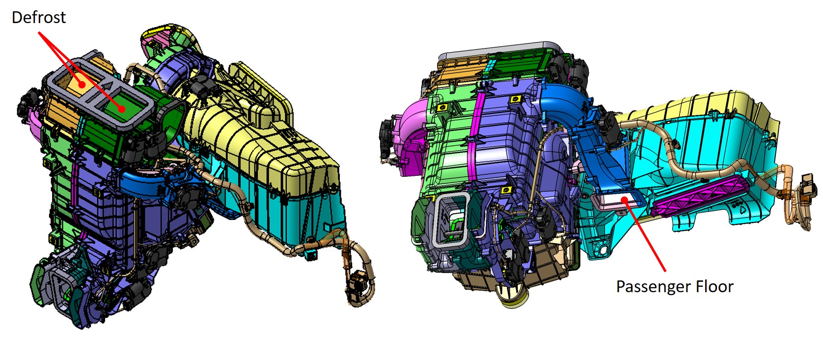
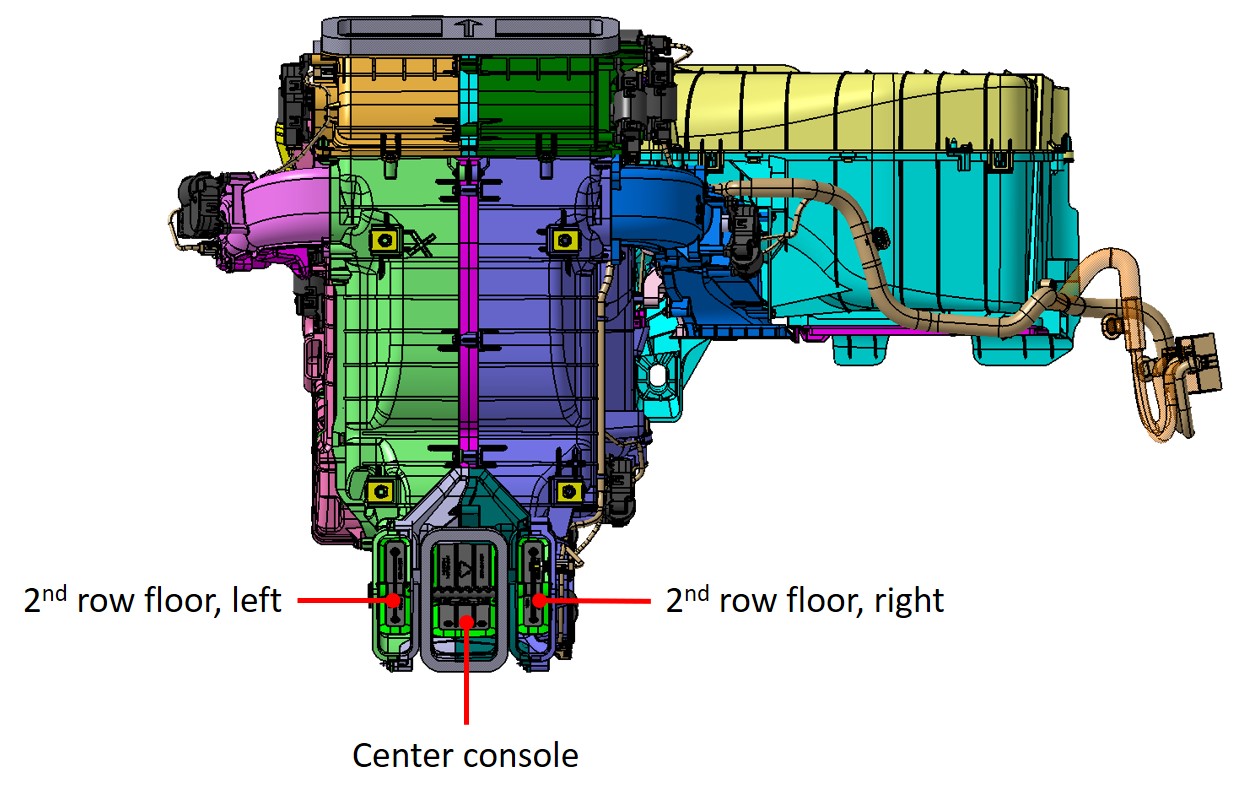
- Actuators (Driver Panel, Passenger Panel, Driver Floor. Passenger Floor, 1st Row Bypass, 2nd Row Bypass, Intake, Defrost, 2nd Row Floor, Center Console,)
- Duct Air Temperature (DAT) Sensors (Defrost, Driver Floor, Passenger Floor, 2nd Row Floor)
- Evaporator Air Temperature (EAT) Sensor
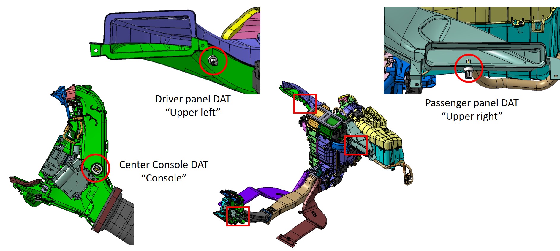
The following DAT sensors are located in the HVAC Ducts, not in the HVAC case:
- Driver Panel
- Passenger Panel
- Center Console
The HVAC system controls the temperature, humidity, flow volume, distribution, and quality of air within the vehicle to achieve and maintain the conditions requested by the occupants.
In Fresh Air mode, outside air enters through the openings at the base of the windshield and into a HEPA filter. In Recirc Air mode, the cabin air enters the HVAC case through a recirc combination filter that filters both particulates and gas. The Inlet Actuator controls the position of the Fresh/Recirc air door allowing full Fresh, full Recirc, or a blend of both Fresh and Recirc air into the HVAC case.
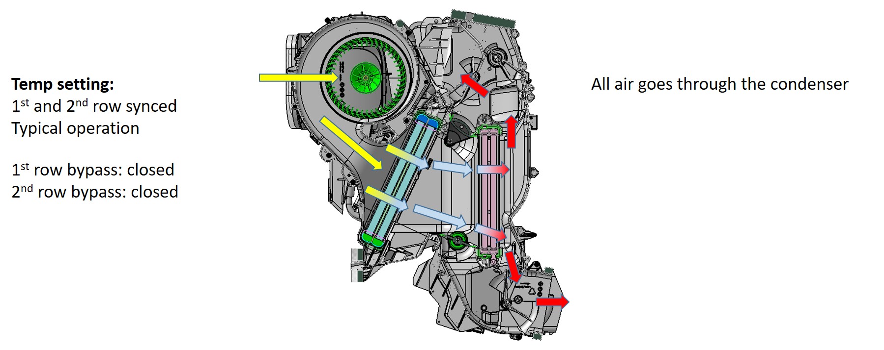
Air is drawn into the HVAC case by the integral blower motor located under the center of the instrument panel. The air then flows through the evaporator, followed by the condenser. When the air conditioning is required, the evaporator cools and dehumidifies the air. When heating is required, the condenser heats the air.
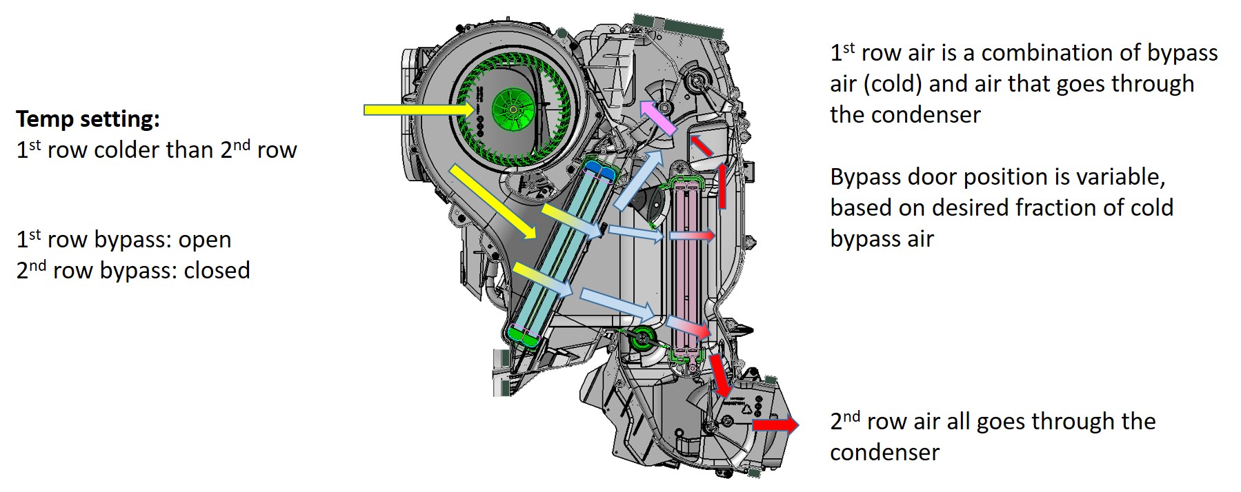
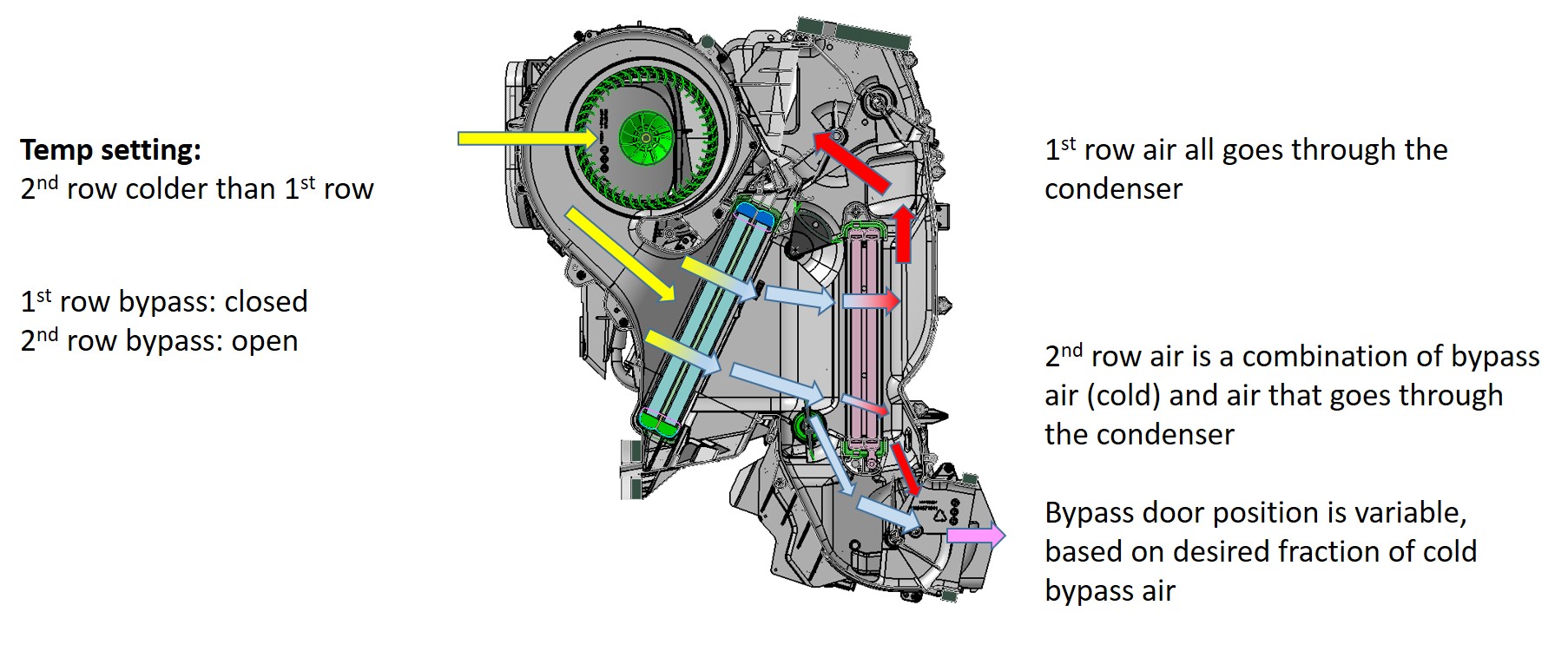
The HVAC case has TriZone operation that allows not only temperature split between driver and passenger, but also allows temperature split from cabin front-to-rear. Front-to-rear temperature split is accomplished by the 1st row bypass actuator and 2nd row bypass actuators. When the set temperature in the front is colder than the rear, the 1st row bypass actuator is open and the 2nd row bypass actuator is closed. When the set temperature in the rear is colder than the front, the 1st row bypass actuator is closed and the 2nd row bypass actuator is open.
All the actuators are motor-controlled and have linear potentiometer output based on HVAC door position. The actuator motors operate on 12+ VDC, with an internal potentiometer which uses 5 VDC reference and 0 VDC to 5 VDC potentiometer feedback.
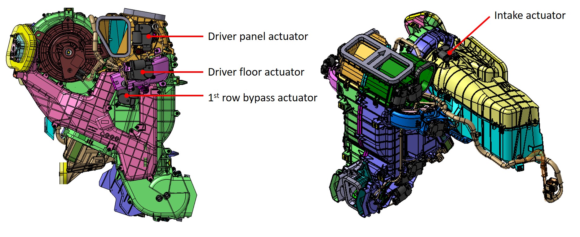
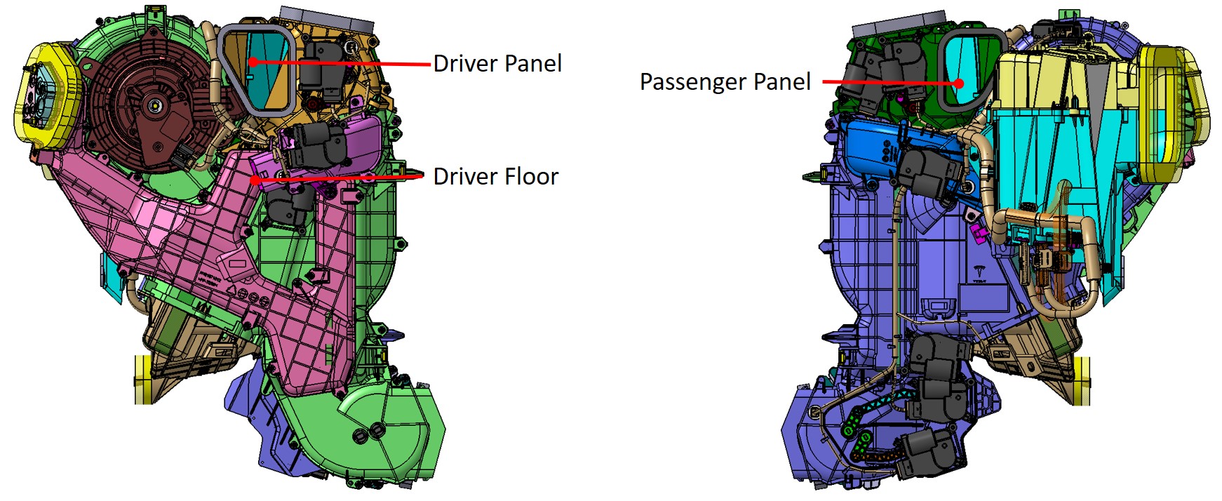
HVAC Case - Actuators (Left Hand Side)link
 |
|---|
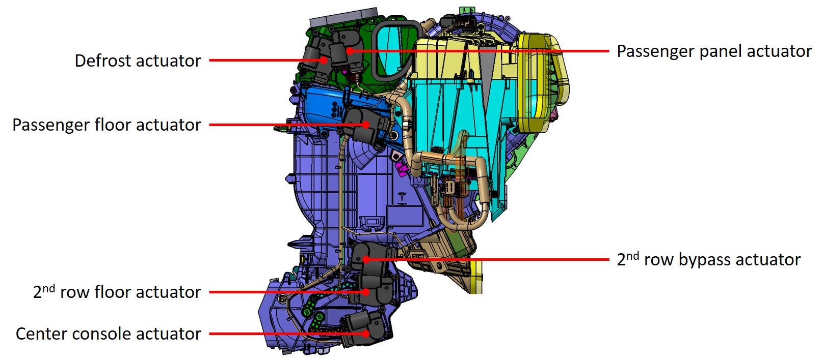
HVAC Case - Actuators (Right Hand Side)link
 |
|---|
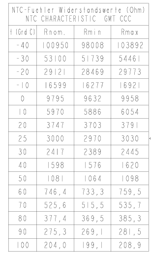
HVAC Case - Duct Air Temperature (DAT) Sensorslink
 |
|---|
 |
|---|
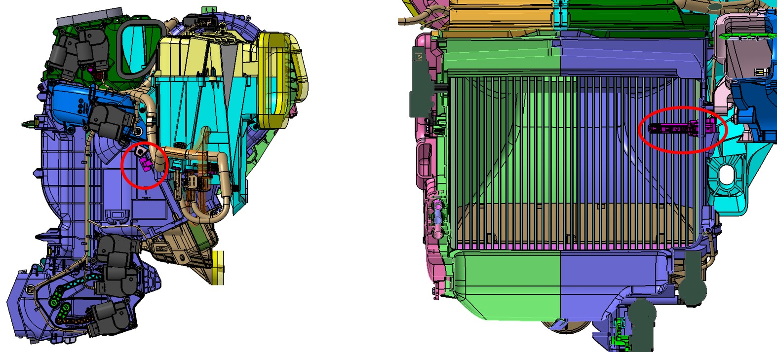
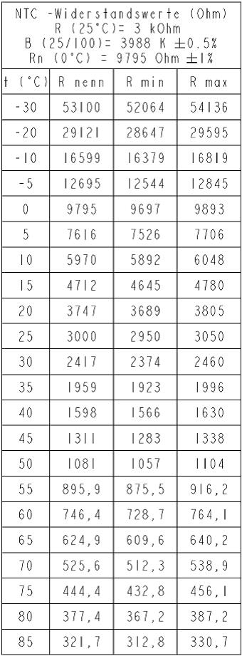
HVAC Case - Evaporator Air Temperature (EAT) Sensorlink
 |
|---|
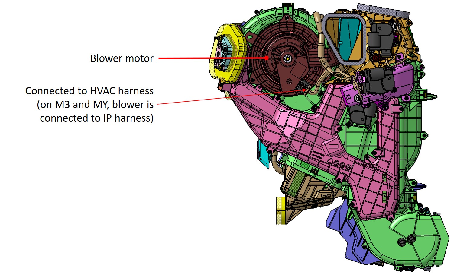
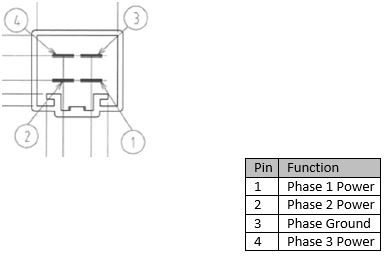
Blower Assemblylink
The HVAC case blower motor is a maintenance free, 3-phase BrushLess DC (BLDC) motor. The motor speed is controlled by the right vehicle controller (VCRIGHT), which varies the DC voltage (12V battery) to each of the 3-phases in the motor. Maximum motor operating current is 35A and the motor bearings are pre-lubed for life. The motor is permanently attached to the fan scroll, creating a blower assembly. The blower assembly is serviceable from the HVAC case.
Note
Duct Air Temperature (DAT) Sensor Diagnostics – See Appendix C.
Evaporator Temperature Sensor Diagnostics – See Appendix D.
Blower Motor Diagnostics – See Appendix E.
 |
|---|
HVAC Case – Doorslink
 |
|---|
 |
|---|
 |
|---|
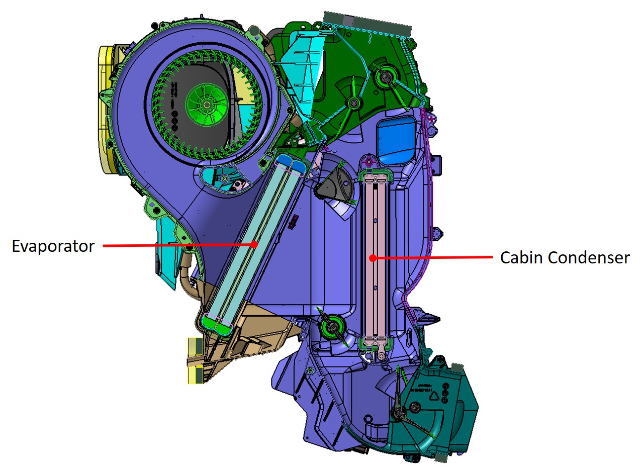
Evaporatorlink
The evaporator is integral with the HVAC case located under the dash. It cannot be removed independently of the HVAC case. High pressure, low temperature refrigerant changes from liquid to vapor as it enters the evaporator and absorbs large quantities of heat as it changes state. As the air passing through the evaporator cools, moisture in the air condenses on the evaporator surface, drying the air that is delivered to the interior of the vehicle. Excess moisture from the evaporator collects in the bottom of the HVAC case and is drained through a port located at the lowest portion of the HVAC case. The port exits through the firewall. The inlet and outlet pipes of the evaporator are routed through the firewall to the PentaPort connection. A foam seal surrounding the PentaPort connection provides an air and water seal at the opening in the firewall.
Condenserlink
The condenser is integral with the HVAC case located under the dash. It cannot be removed independently of the HVAC case. High pressure, high temperature refrigerant changes from vapor to liquid as it enters the condenser. During this process, the condenser emits large quantities of heat into the cabin as the refrigerant changes state.
 |
|---|
HVAC Case – Heat Exchanger Refrigerant “Pentaport”link
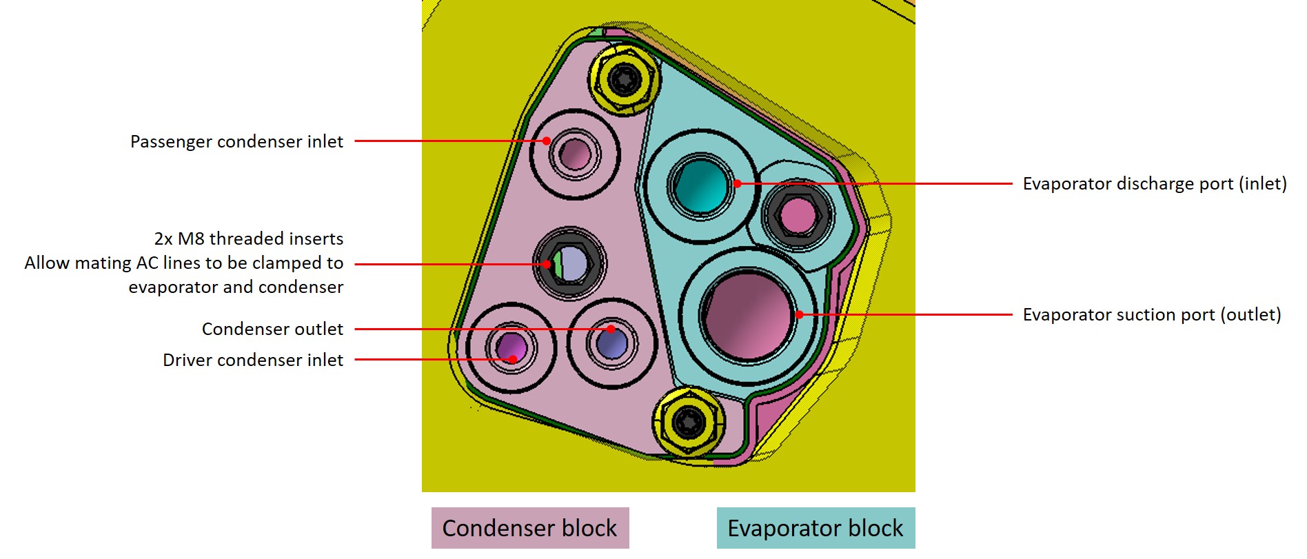 |
|---|
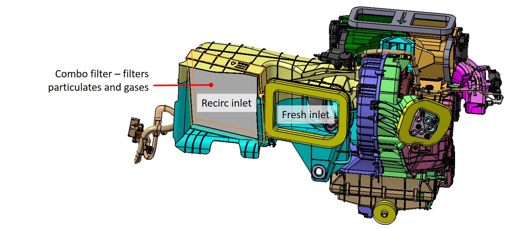
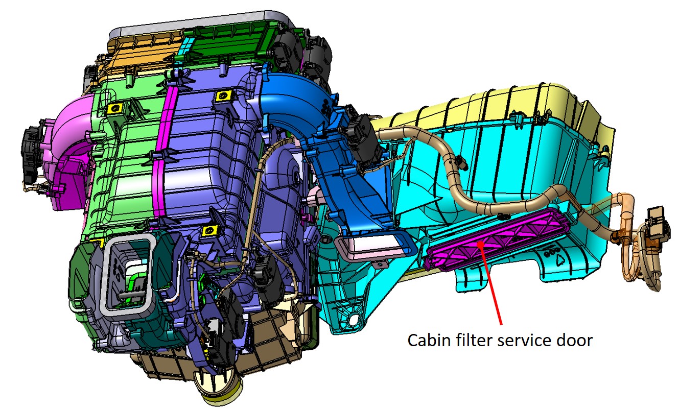
HVAC Case – Cabin Filterlink
 |
|---|
 |
|---|
2021+ Model X has two cabin air filters. The HEPA filter is located under the hood, while the recirc filter is located in the HVAC case. The recirc filter service door, located on the bottom of the HVAC case, uses an integrated push-tab rather than a fastener for easy removal.
HVAC Case - Air Outletslink
 |
|---|
 |
|---|
 |
|---|
HVAC Case - TriZone Operationlink
 |
|---|
 |
|---|
 |
|---|
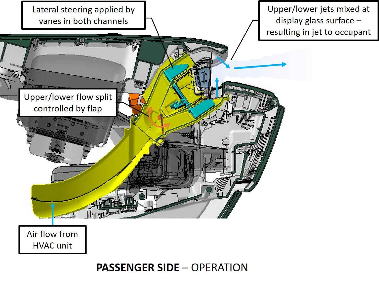
Cabin Airwaveslink
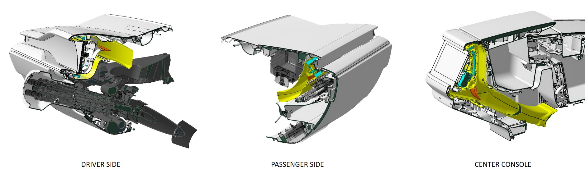
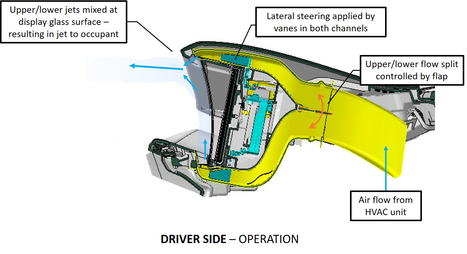
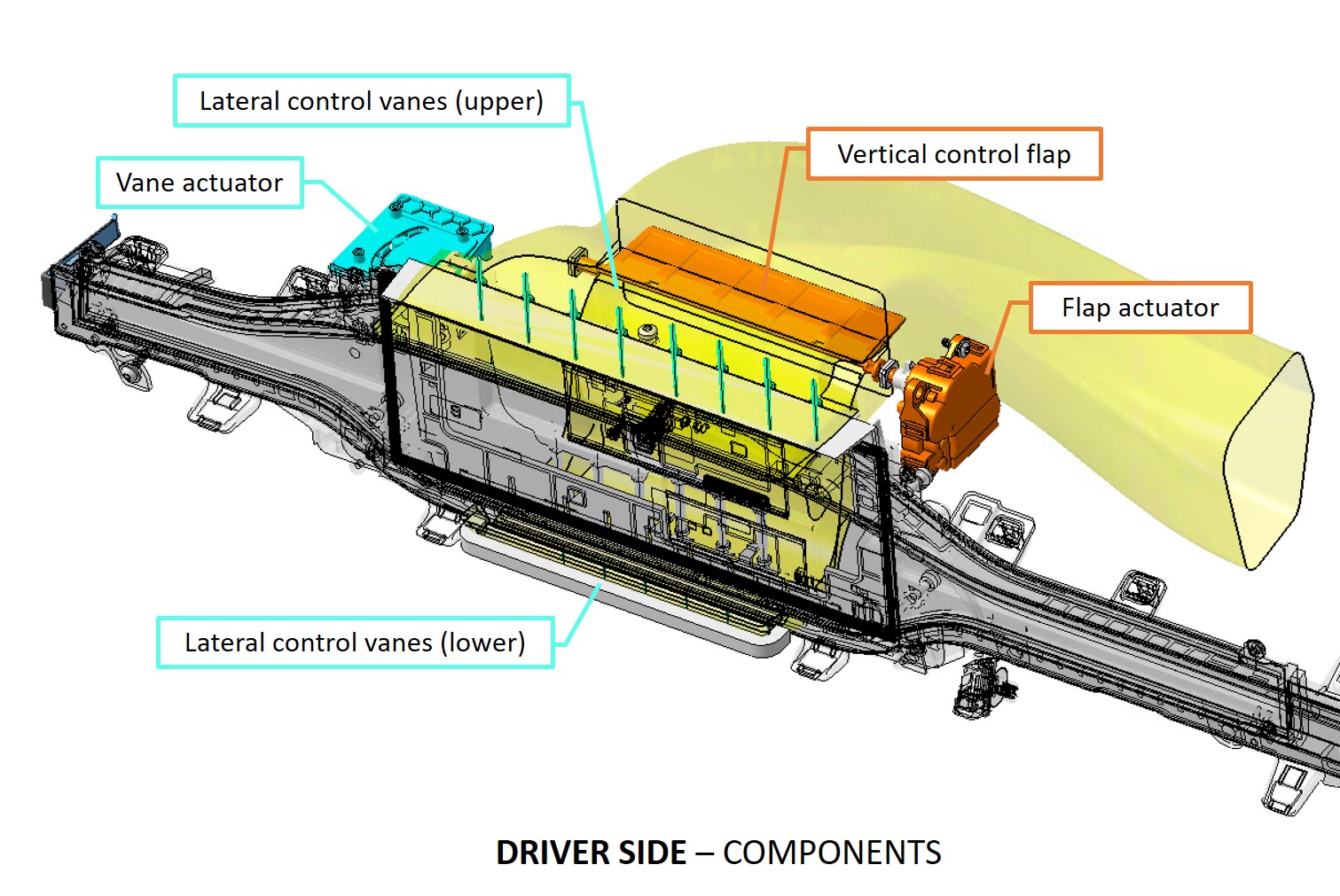
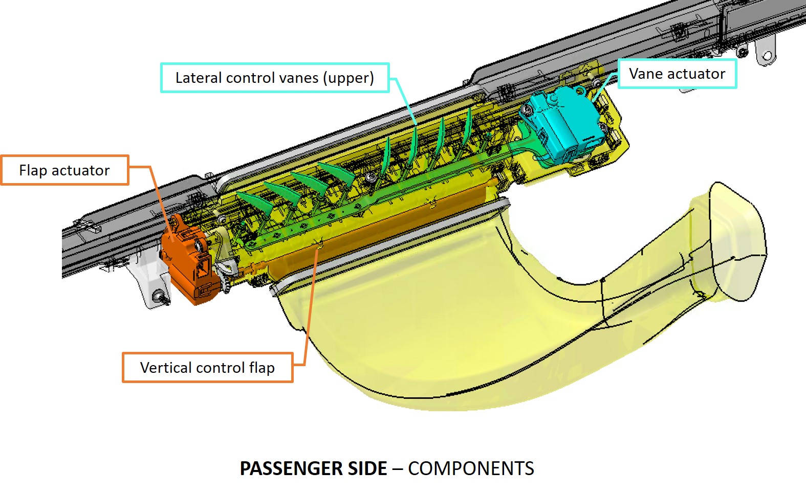
2021+ Model X instrument panel airwaves are similar in operation to Model 3/Y, but there are a few key differences. The lateral control is achieved through steering vanes, similar to Model 3/Y, although the integration of these into the system is slightly different. The vanes and associated kinematics are not contained in a small individual unit as on 3/Y, but are integrated into the larger vent assembly.
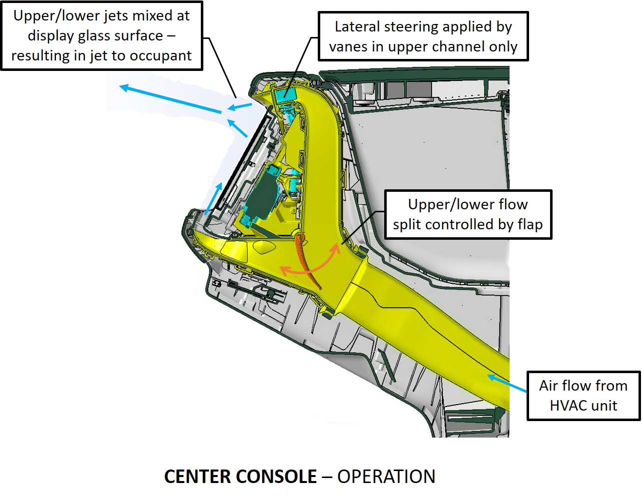
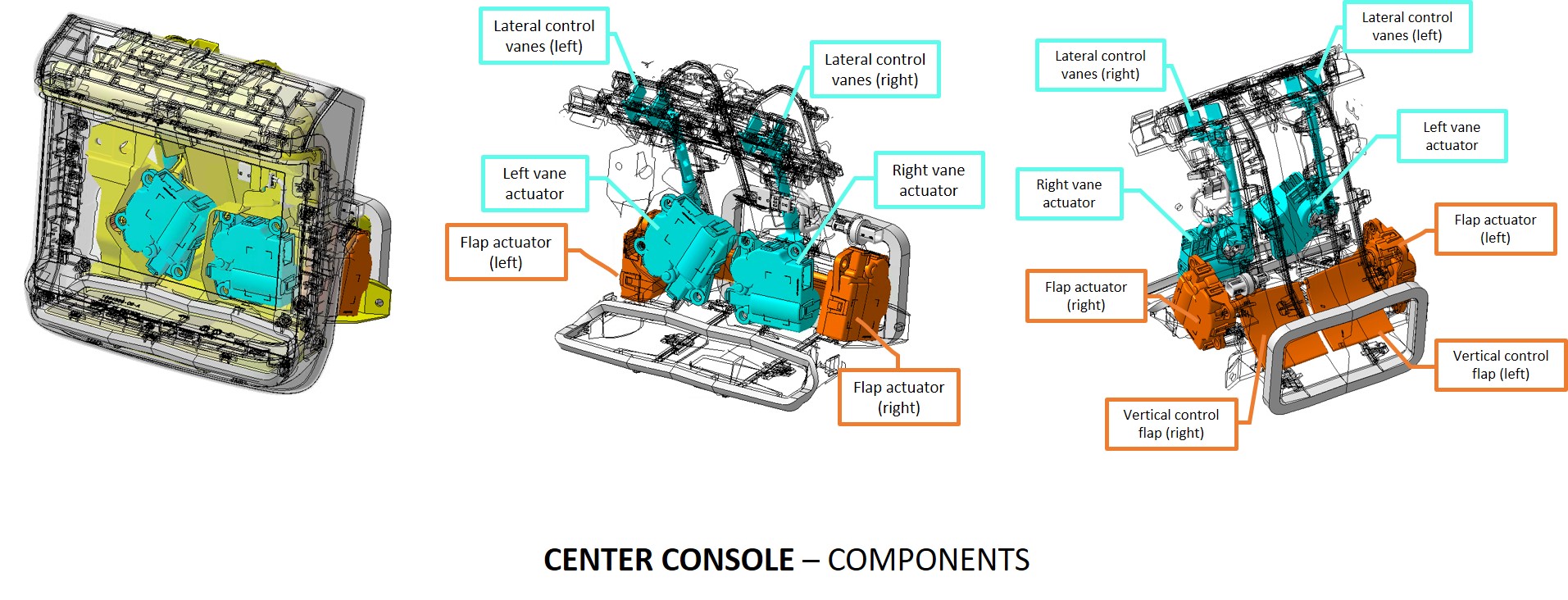
Vertical control is achieved through varying the air flow split between two outlets set at opposing angles, configured to meet into a single airflow jet. This is controlled by a direct-driven flap integrated into the vent unit. Below are the layouts and key elements for the driver side, passenger side, and center console.
 |
|---|
 |
 |
 |
 |
 |
 |
Appendixlink
Appendix A – Specifications and Capacities Section For Refrigerant and Oil Informationlink
- R134a refrigerant charge 1020g
- Tesla POE ND-11 oil (part number 1031093-00-A)
- Service A/C Compressor prefilled with (250g) ND-11 oil
Appendix B - Slimline Seal lookup tablelink
 |
|---|
Appendix C - Duct Air Temperature (DAT) Sensor R-T chartlink
 |
|---|
Appendix D - Evaporator Temperature Sensor R-T chartlink
 |
|---|
Appendix E – Blower Motor Diagnosticslink
 |
|---|