Safety and Restraintslink
Last updated: October 20, 2023
Safety and Restraint Component Locationslink
 |
|---|
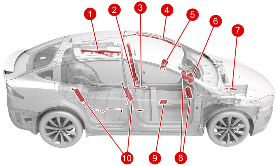
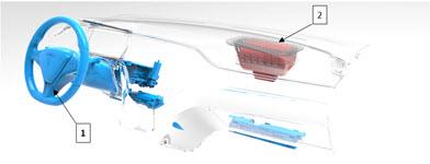
| 1. 2nd Row Head Airbag (x2) 2. Pyrotechnic Shoulder Seat Belt Pre-Tensioner (x4) 3. Pyrotechnic Lap Seat Belt Pre-Tensioner (x2) 4. Curtain Airbag (x2) 5. Driver Airbag 6. Passenger Airbag 7. Pyrotechnic HV Cutoff 8. North America only: Knee Airbag (x2) 9. Restraint Control Module 10. Seat Airbag (internal to seat) (x4) |
| Restraints Mechanical System |
 |
|---|
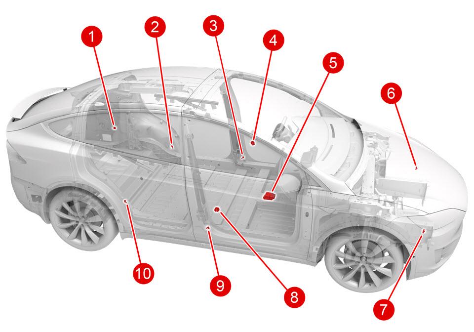
| 1. D-Pillar 2D Accelerometer -LH 2. C-Pillar 1D Accelerometer -LH 3. B-Pillar 1D Accelerometer -LH 4. Door Pressure Sensor -LH 5. Restraints Control Module 6. Headlamp bracket 1D Accelerometer -LH 7. Headlamp Bracket 1D Accelerometer -RH 8. Door Pressure Sensor -RH 9. B-Pillar 1D Accelerometer -RH 10. C-Pillar 1D Accelerometer -RH |
| Restraints Sensor and Electrical System |
 |
|---|
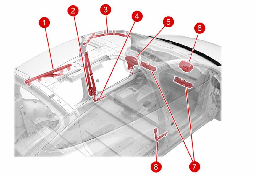
| 1. 2nd Row Head Air Bag 2. Shoulder Pre-Tensioner 3. 1st Row Curtain Airbag 4. Lap Pre-Tensioner 5. Driver Airbag 6. Passenger Airbag 7. North America only: Knee air bag (x2) 8. Lap Pre-Tensioner |
| Safety Deployment System |
Safety and Restraint Operationlink
The Tesla Supplementary Restraint System (TSRS) is designed to work in conjunction with the seat belts. These devices supplement, but do not replace, the protection afforded by the seat belts. Seat belts are proven to be the single most effective safety device in a vehicle, and should always be worn. Properly worn seat belts also ensure that the occupant is seated in the optimum position to benefit from the full effectiveness of the airbags and seat belt pretensioners.
The Model X has a large variety of airbags which, when combined with seat belts, safely dissipate the occupant’s kinetic energy during an impact. The amount of kinetic energy airbags must absorb depends on the speed of the vehicle and the mass of the occupant. Advanced dual Stage airbags like those in front row of a Model X are able to tune this energy absorption for different speeds or passenger sizes. Seat sensors like the occupant classification system (OCS) and seat track position give an indication of the passenger mass while crash accelerometer and velocity measurements allow for an understanding of the occupant speed. The information is continuously fed into the Restraint Control Module (RCM) where, in the event of a crash, it can determine the appropriate energy absorption needed from the seat belts and airbags.
Seat belts in the front row are equipped with a deployable load limiter, which tunes the amount of energy that the seat belts absorb from the occupant. To minimize the risk of occupant injury the load limiter can be deployed to lessen the maximum tension in the seat belts. When load limiters are deployed, the energy absorbed by the seat belts is decreased, which allows the airbags to absorb more occupant energy. The system is only deployed in frontal and side impacts where the airbags are most effective. In cases with combined amount of forward and lateral motion or any rear impact deployed, the seat belts absorb as much energy as possible.
Airbags are most effective when the occupant is in a specific position as they are deployed. Seat belt pretensioners are used to help prepare the seat belt to absorb occupant energy and move the occupant to the best position before they impact the airbag. Front row occupants in the driver and passenger seats are positioned from both the shoulder and lap belts by two pyrotechnic retractors located in the lower B-pillar trim. Second row outboard passengers are positioned by the shoulder belt from a pyrotechnic retractor in the back of each seat.
The first row and second row outboard occupants are protected in crashes with a lateral motion (side, angled, or offset type crashes) by side curtain and seat airbags. The front row curtain airbags deploy down from the upper A-pillar trim area. The outboard second row occupants are protected by head airbags that deploy from the upper section of the lower rear door trim. Seat airbags inflate from the outboard seat bolsters to soften occupant hip and leg contact with the door trims. In North American markets. the front row occupant’s legs are also protected from trim contact in a frontal impact by knee airbags.
In the event of a collision with the drive rail on, the pyrotechnic fuse can be deployed to isolate high voltage to the HV Battery. All crash modes (including front, side, rear or charger), which exceed the programmed threshold will trigger the pyrofuse. The fuse disables high voltage by physically disconnecting 12V contactor power to the HV Battery, which isolates any high voltage to the battery behind the contactors. The same circuit is opened when disconnecting the first responder loop in the vehicle.
All deployable safety systems such as airbags, seat belt pretensioners, and the pyrofuse are singe use pyrotechnic devices and must be replaced after any type of deployment. All will completely dispose of their pyrotechnic component within 185ms of impact detection. Seat airbag deployment will require a full seat replacement in the event of a crash with lateral motion. While deployed safety devices are designed to be inert after a crash to protect occupants and first responders, any pyrotechnic device should be handled with all proper procedures and care according to the vehicle Service Manual.
The Gen 3 charger in Model X is equipped with its own independent crash sensing and deployment logic. It will protect HV by opening contactors if a crash event is detected while the charger is powered and contactors are closed. The charger crash alert latched in the battery managment system (BMS) and can only be reset after inspection in service.
Airbag Deployment Situations - Drive Rail Onlink
The TSRS is designed to deploy safety devices in only specific conditions. An overview of deployment cases is listed below to help understand expected system behavior.
- Flat frontal impact (low speed): Impact is below a certain speed, but with deceleration above calibration threshold with force directed mostly along the direction of travel. The control module will deploy pyrotechnic fuse, all pretensioners, knee airbags, and only Stage 1 front upper body airbags because occupant kinetic energy is low. In this case, Stage 2 deployment could force the occupant’s body backwards resulting in unwanted head and neck stress. To avoid this scenario, Stage 2 is not deployed and automatically goes to disposal to protect occupants and first responders. Side airbags are NOT deployed because there is no lateral energy to absorb from the occupant. The RCM continues to monitor for any additional impacts, and can still deploy remaining systems in any later side, rollover or charger impact.
- Flat frontal impact (high speed): Impact velocity is above a certain speed with force directed mostly along the direction of travel. The same systems are deployed as a low speed frontal, but front upper body airbags can deploy both Stage 1 and Stage 2 for maximum energy absorption. The RCM will use information about the mass of occupant to determine the appropriate deployment strategy. The front passenger airbag can also deploy the active vent to lessen absorption energy for small occupants.
- Angled frontal impact (low speed): Impact is below a certain speed, but with deceleration above calibration threshold and rotation of the vehicle detected. The control module will deploy the same components as a low speed frontal, except the seat belt load limiters. Without load limiting, the seat belts are able to absorb the extra lateral force of the occupants. Side airbags are still not deployed due to risk of delivering to much lateral force to the occupants.
- Angled frontal impact (high speed): Impact velocity is above a certain speed and rotation or lateral movement is detected. The safety system will deploy the safety components to absorb maximum energy from the occupant. Pyrotechnic fuse and all airbags (front, knee, side, curtain and seat) are deployed unless suppressed by the occupant classification system. Pretensioners will fire if the seat belt buckle signals are latched. Advanced front airbags Stage 1, Stage 2 and active vent deployment or disposal is dependent on occupant size. The front seat load limiter is not deployed to allow maximum energy absorption by the seat belts.
- Side impact: Pyrotechnic fuse, all pretensioners, seat side airbags, and curtain airbags are deployed if a side impact is detected. Front airbags are not deployed because there is little to no forward deceleration and thus no forward force to absorb. The RCM continues to sense for a frontal impact and can deploy additional systems if needed.
- Rollover: Pyrotechnic fuse, all pretensioners, and seat side and curtain airbags are deployed biased on a deployment angle as measured in the Restrains Control Module.
- Rear impact: Only pyrotechnic fuse and seat belt pretensioners are deployed. No airbags are deployed because they would deliver energy to the occupant in the wrong direction.
- Charger impact: If a charger impact is detected, then the pyrotechnic fuse is deployed to protect the High Voltage system from isolation loss. The charger protection sensor watches for acceleration in the forward and lateral directions so it can be triggered by impacts from behind or the side. No other safety systems will be deployed if only a charger impact is detected. A side or rear impact can be triggered independently during a charger impact, and will deploy safety components according to their normal algorithms.
Although the airbags and pretensioners are designed to be triggered electrically, they are pyrotechnic devices and could deploy unexpectedly— even when not connected to an electrical source— if proper transport, storage, and handling methods are not followed. Always follow Service Manual procedures when diagnosing or repairing the Tesla Restraint System. Only use Tesla-approved equipment to intentionally deploy a pyrotechnic device for disposal purposes.
Warning
Accidental deployment can cause damage and personal injury. Always refer to the Owner's Manual for correct use of the Tesla Restraint System and seat belt systems, and to the Service Manual for correct fitment, repair, and disposal of system components.
Airbag Deployment Situations - Drive Rail Offlink
The Gen 3 charger has the ability to protect the high voltage system in the event of an impact that could degrade isolation during AC and DC charging. An accelerometer sensor internal to the charger monitors for impacts only when drive rail is OFF. If an impact that exceeds the calibration threshold is detected the charger will do the following:
- Send CAN message to BMS instructing immediate opening of HV contactors.
- Open Fast Charge contactors.
- Run a Fast Charge contactor weld check.
- Trigger urgent CAN alert to pull vehicle CAN logs.
- Instruct BMS not to close contactors again.
Deployment of this message will not allow HV contactors to close again, and will require service.
Starting and Drivinglink
The airbag warning indicator displays for six seconds when the vehicle is switched on as a system check. After the system check, if there is no active fault, the indicator turns off and stays off. If there is an active fault, the indicator turns off for one second and then turns back. Some faults will latch the light on for the remainder of the drive cycle, while others can clear and the light will shut off. Consult Toolbox for airbag light behavior of specific faults.
The front seat belt indicator and chime are controlled by the Restraint Control Module based on input from the Seat Belt Reminder (SBR) switches and the Occupant Classification System (OCS). The passenger seat SBR and the OCS are inputs to the RCM. The front seat SBR system has three classes of operation for each seat dictated by regulatory requirements.
If the seat belt is fastened during any of the three class, the chime stops and the indicator turns off.
Second and third row Seat Belt Reminders will play a chime once for 6 seconds if they are unbuckled at the start a drive cycle. The chime will also play if an occupied seat is unbuckled during a drive cycle. The instrument cluster will display the occupied and unbuckled seat on a bird’s eye view of the vehicle. The occupancy sensors can be triggered by any object above approximately 30 lbs.
Component Descriptionslink
Model X is equipped with a Tesla Supplementary Restraint System (TSRS). The system comprises the following components:
- Restraint Control Module (RCM)
- Single axis acceleration sensors
- Dual axis acceleration sensors
- Piezo-electric door pressure sensors
- Occupant classification system (OCS) (if equipped)
- Seat track position sensor
- Seat belt reminder switches
- Driver and passenger dual-Stage front airbags
- Driver and passenger knee bolster airbags - Available only in North America markets.
- Driver and passenger seat side (pelvis/torso) airbags
- Second row seat side (pelvis/torso) airbags
- First row side curtain airbags
- Collapsible steering column
- Driver and passenger seat belt pretensioners
- Second row outboard seat belt pretensioners
- Driver and passenger seat belt load limiters
- Second row head airbags
- Pyrotechnic fuse
Restraint Control Module (RCM)link
 |
|---|
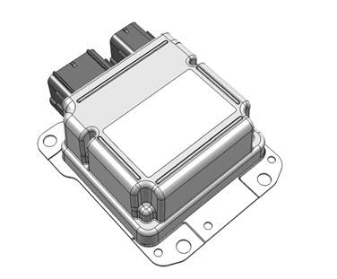
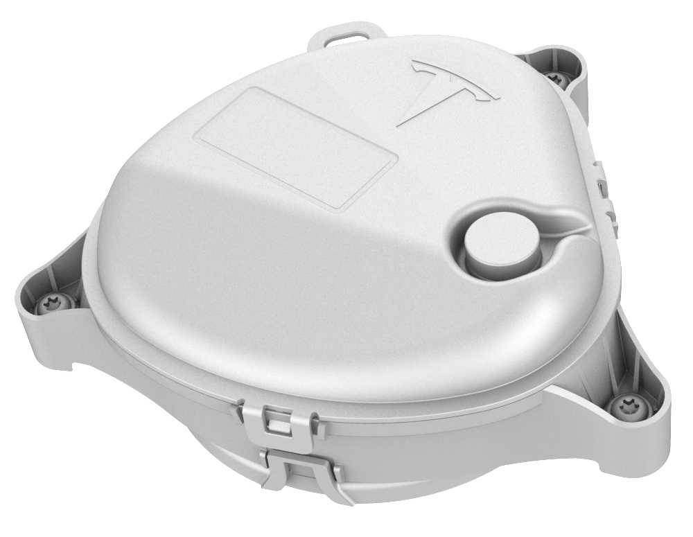
| RCM |
The TSRS is controlled by the RCM (RCM), which includes fault detection and warning circuits. If a fault is detected, an indicator light in the instrument panel notifies the driver.Alerts for this component are retrievable using vehicle CAN logs, Vitals, or Periscope.
The RCM is calibrated specifically to the vehicle model. It contains accelerometers to measure forces acting on the vehicle, and circuits for monitoring the condition of all pyrotechnic devices. It is the primary device that commands the deployment of all TSRS components. During a deployment, the system will run current through individual components to trigger the pyrotechnics. Each Stage and part has its own independent wire loop for this triggering signal.
The RCM monitors the restraint system electrical components and circuitry when the drive rail is on. The Restraint Control Module uses an internal six axis inertial measurement unit (IMU) to monitor 3D velocity and acceleration changes in the vehicle. The module is located under the center cluster near the vehicles center of gravity to sample the motion of the entire vehicle and isolate it from chassis and body vibration as much as possible. The module can be affected by jolts or knocks to the center console from passengers in the vehicle.
The acceleration data from the RCM is also broadcast on private CAN to the iBooster and ESP modules for use in the traction control algorithm. If the internal sensor detects a high acceleration event it looks to data from the satellite sensors to determine the type and severity of the crash. The Restraint Control Module will only deploy safety components if both of these sensor signals are available and agree. When the signals exceed the per-calibrated values, the RCM directs current through the appropriate deployment loops to deploy the airbags, pretensioners, and pyrotechnic fuse as necessary.
The RCM records certain aspects of the event data when a deployment occurs and displays the AIRBAG indicator located on the instrument cluster. The module holds data for a maximum of 2 independent deployment events. The module will also attempt to store near deploys into the record, but those can be overwritten (in first in, first out order) by additional near or full deployments. If both records have been stored as full deployments the module will not allow any additional records. The data is only available when pulled by engineering and used for reference purposes. The system is entirely separate from the data storage on the gateway/Carlogs or on garage after a crash is detected.
When deployment occurs, the RCM sends a collision detection CAN message to the body controller which then does the following actions:
- turns on the interior lights
- turns on hazard lights
- unlocks all doors
- unlocks the trunk.
The gateway will: - initiate a standard log pull - pull and package the Restraints Control Module information - attempt to gather any Automated Emergency Braking or Side Collision Avoidance data from the Driver Assistance System.
The vehicle will also attempt to package these items and immediately upload them to the vehicle servers.
The RCM performs diagnostic monitoring of Tesla Restraint System electrical components and deployment loops for malfunctions while drive rail is on. The module requests the instrument cluster to display the airbag indicator light if a fault (bad deployment circuit or missing sensor) is detected. If the RCM stores a DTC and sends a CAN message, that is stored in the vehicle log.
Impact Sensorslink
Accelerometer Impact Sensorslink
Eight acceleration type impact sensors are fitted to the Model X in the following positions:
- Front bumper carrier sensors (x2) - accelerometers
- ‘B’ pillar sensors (x2) - accelerometers
- ‘C’ pillar sensors (x2) – accelerometers
- ‘D’ pillar (Left) sensor – accelerometer
 |
|---|
| Accelerometer Impact Sensors |
 |
|---|
| Accelerometer Impact Sensors (D-Pillar) |
The accelerometer type impact sensors contain a sensing device that monitors vehicle acceleration (positive and negative) and pressure inside the front doors. The impact sensors send data to the Restraint Control Module. The RCM uses the data from the sensors to determine if a collision is severe enough to warrant airbag(s) and/or seat belt pretensioner(s) deployment.
The Restraints Control Module is powered by the drive rail which is off during charging. The charger in the rear driver side quarter panel is responsible for some HV protection. It actively monitors its internal accelerometer for movements that would indicate a collision while contactors are closed during charging. If high accelerations are sensed the charger will send a high priority CAN message to the BMS to open contactors to isolate HV. The battery responds to the charger crash message in the same way as the hardware over current detection. Contactors will be blocked from closing until inspected and cleared by service and engineering.
Pressure Impact Sensorslink
 |
|---|
| Pressure Impact Sensors |
The Piezo-electric pressure sensors mounted inside the front LH and RH doors measure the dynamic pressure change caused by deformation of the door in a side crash. They require a sealed door compartment to work properly.
The inputs from the pressure sensors are processed by the Restraint Control Module to deploy the side airbags and the seat belt pretensioners.
Warning
It is extremely important to always reinstall or replace any plugs or tape removed from the door shells when servicing components inside the door. The pressure sensors are precisely calibrated to respond to pressure changes within the door in the event of a collision. Opening more holes in the door creates more escape paths for air, which diminishes the sensor's ability to accurately detect a side impact, and can negatively affect airbag deployment
Occupant Classification Systemlink
 |
|---|
| 1. OCS sensor mat (fluid filled) 2. ECU |
| Occupant Classification System (OCS) |
The Occupant Classification System (OCS) monitors the seated weight to estimate the type of occupant sitting in the front passenger seat, and communicates the status to the RCM using a CAN signal. The Restraint Control Module uses this information to determine whether to enable or suppress the deployment of the front passenger airbag and corresponding knee airbag.
If the occupant classification system detects an empty or child seat in the front passenger seat, the front passenger upper body airbag is disabled. The intent is to detect child booster or rear facing infant vehicle seat where even Stage 1 deployment provides too much energy absorption for these types of occupant. Child seat detection is based on the Belt Tension Sensor (BTS). Child seats use a higher seat belt tension than would be comfortable to a normal occupant. The BTS will detect that tension and disable passenger airbag deployment.
The OCS consists of an electronic control unit (ECU) a sensor mat in the seat, a harness, and a PASSENGER AIRBAG ON/OFF indicator.
The OCS measures the pressure change in the mat fluid (and pattern through cell arrangement) to determine the type of occupant in the front passenger seat. The ECU compares this pressure change to the internally stored threshold to determine whether the seat is occupied, and what size of passenger is detected (see table below). The OCS sends this information to the RCM to either disable the front passenger airbag and knee airbag. The occupant size determines if the active vent is used during higher energy collisions. The Active Vent will lower the force to the occupant which is preferable on a smaller occupant.
If the OCS senses a small or large occupant, it will check for the seat belt buckle status. If the OCS determines that a seat belt is unbuckled while occupied, it will trigger a seat belt reminder indicator and chime.
| Front Passenger Seat Occupancy | Passenger Airbag Indicator Center Display - North America | Passenger Airbag Stages |
|---|---|---|
| Seat empty, child seat, or small child | PASS AIRBAG OFF | None |
| Small occupant (~20 to 50lbs) | PASS AIRBAG ON | 1st, 2nd and Active Vent |
| Large occupant (>~50lbs) | PASS AIRBAG ON | 1st and 2nd |
Note
Values are approximate weight place on seat bottom. Seat position and weight distribution can affect the sensed value. Occupants whose weight is close to the low weight threshold can cause the status to occasionally switch on and off depending on seating position and physique.
The RCM notifies the occupants of the disable status by displaying the PASSENGER AIRBAG ON/OFF indicator in the media control unit (MCU). If the MCU goes out with the drive rail on, the instrument cluster will display the status of the passenger airbag.
If a fault is detected, the OCS sends a message to the Restraint Control Module. The RCM responds by sending a command message to the instrument cluster to display the TSRS airbag indicator.
Calibration of the system when it is new is done using a Toolbox routine common to all platforms.
Note
The Occupant Classification System (OCS) is precisely calibrated for each individual seat at the factory. When servicing the OCS or the Seat Assembly with OCS, Tesla’s service procedures must be followed so that OCS system function is not compromised. Any service performed on the Seat Assembly with OCS must be followed by a Seat Re-Zero procedure.
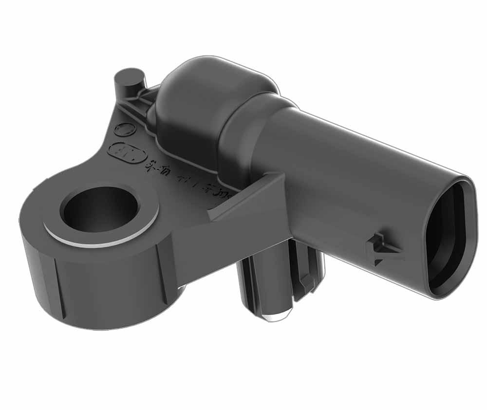
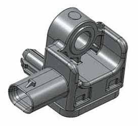
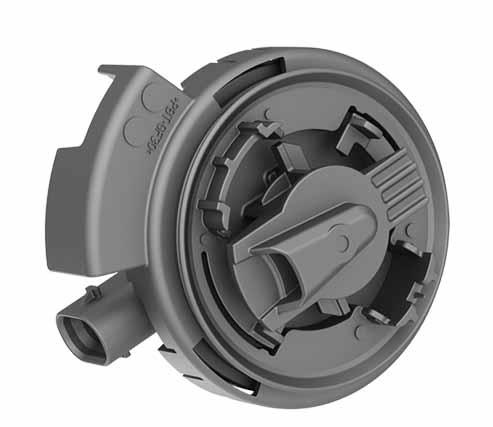
Seat Position Sensorlink
 |
|---|
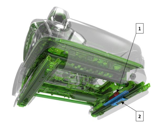
| 1. Seat position sensor (hall effect) 2. Fixed sensor plate (shunt) |
| Seat Position Sensor |
The seat position sensor (SPS) is used to determine the distance between the driver seat and the steering column. Information from the SPS allows the RCM to disable Stage 2 of the airbag if the seat is forward of a predetermined point in seat track travel (closer to the airbag module). The comfort adjust position of the steering column is not accounted for when making deployment decisions. The SPS is a Hall Effect sensor, mounted on the outboard seat track of the driver seat. The seat track includes a metal bracket that shunts the SPS magnetic circuit, creating two states of seat position. The sensor moves with the seat while the plate stays fixed to the riser. Once the sensor moves far enough forward the sensor moves past the metal shunt and the state switches. The shunted state represents a rearward seat position. The non-shunted state represents a forward position. These 2 states are inputs to the RCM.
When an SPS informs the RCM that the state 1 threshold is reached (seat is rearward), the RCM does not disable Stage 2. When the state 2 threshold is reached (seat is forward), the RCM disables Stage 2 deployment of the driver airbag.
Note
Stage 2 deployment is also disabled if the Restraint Control Module detects that the sensor is not operating as expected.
The sensor is attached to the seat track with two rivets.
Seat Belt Reminder Sensorlink
 |
|---|
| Seat Belt Reminder (SBR) Sensor |
The Seat Belt Reminder (SBR) sensors are fitted in the seat cushion of the appropriate seat. Seat Belt Reminders are located in driver, 2nd row passenger and 3rd row passenger (if configured) seats. The SBR is not in the front passenger seat because it has an OCS sensor which has SBR capabilities. On all vehicles, regardless of market, the driver seat SBR switch is an input to the Central Body Control module (BCCEN). The BCCEN/Gateway uses driver SRB input for vehicle on/off, gear selection, and parking brake behavior.
The SBRs always actuate for 5th percentile occupants and larger, but may actuate for other smaller occupants or objects below this weight. The second row outboard seat controllers (BCS2R and BCS2L) handle signals from the 2nd and 3rd row SBR and seat belt buckle switches on their respective sides, then broadcasts the status over Body CAN. The middle second row seat controller (BCS2C) handles only signals from its SRB and seat belt buckle. The RCM uses these signals, together with information from each seat belt buckle, to display an indicator light and sound an audible warning if an occupant has not fastened a seat belt.
Pyrotechnic Fuselink
 |
|---|
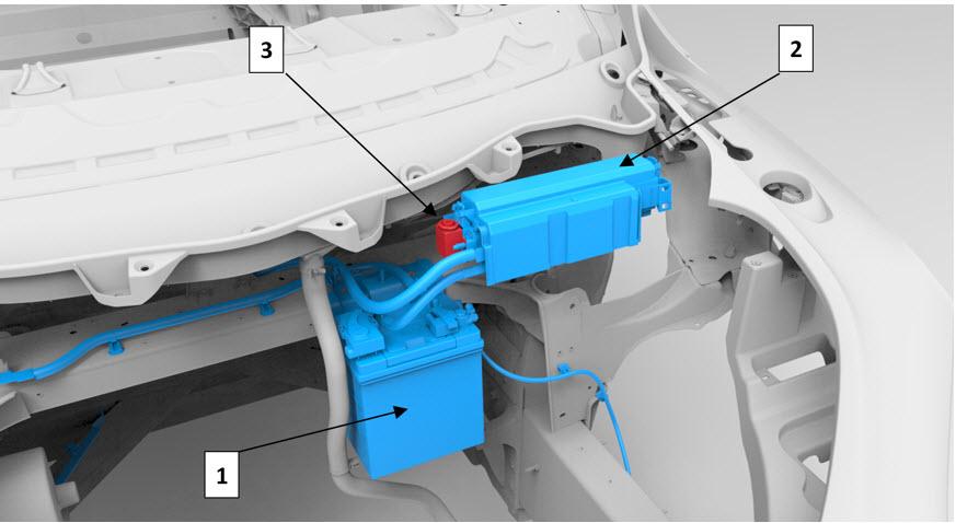
| 1. 12 volt battery 2. Battery fusebox 3. Pyrotechnic fuse F93 |
| Pyrotechnic Fuse |
The pyrotechnic fuse F93 is located on the battery fuse box. The fuse cuts 12V contactor power, which forces the HV battery contactors to open. The RCM fires the fuse anytime the airbags and/or pretensioners deploy. Pyrotechnic fuse deployment isolates high voltage to the HV Battery, which makes the vehicle safe for the occupants and emergency responders if the high voltage system is compromised by collision damage.
It is important to also pull the first responder loop any time a vehicle is to be worked on after a crash. The pyrotechnic fuse displays no physical damage after being triggered and cannot be reset. It always needs to be replaced after any deployment event.
Airbagslink
Warning
Airbags inflate with great force, in a fraction of a second. A vehicle occupant could be seriously injured or even killed if sitting closer than 10 in (255 mm) to the airbag, or if seated incorrectly. Do not place any objects in the path of airbag deployment (such as on top of the passenger side instrument panel)
Airbags consist of a housing, an inflatable airbag, initiating devices, and a canister containing gas generating material.
The driver and passenger upper body airbags have two stages of main bag deployment. For low energy frontal collisions, the airbags deploy at less than full deployment, or Stage 1 of the airbag. For more severe frontal collisions, a full airbag deployment (both Stage 1 and Stage 2) is initiated. The current passing through the airbags ignites the material in the canister, producing a rapid generation of gas. The gas produced from this reaction rapidly inflates the airbag. Once the airbag is inflated, it quickly deflates through the airbag vent holes and/or the airbag fabric.
The passenger front airbag is equipped with a third deployment device called an active vent. An active vent can be deployed to allow the airbag to deflate more quickly, reducing the total energy absorption of the bag. Quicker airbag deflation is useful when trying to steadily absorb the lower energy of a smaller occupant. Active vent deployment will thus depend on information from the occupant classification system in the front passenger seat.
Upon detection of a circuit malfunction, the RCM sets a DTC and informs the driver by displaying the Tesla Restraint System airbag indicator in the instrument cluster.
Driver Front Airbaglink
 |
|---|
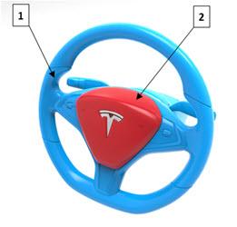
| 1. Steering wheel 2. Driver front airbag |
| Driver Front Airbag |
Mounted on the steering wheel, the driver airbag is a dual Stage front airbag that provides protection from impact with the steering wheel and the surrounding dashboard for adults of all sizes.
Passenger Front Airbaglink
 |
|---|
| Passenger Front Airbag |
The passenger front airbag is mounted behind the instrument panel on the front passenger side. The passenger airbag deploys up through the top of the dashboard trim and then wraps forward around the dashboard and glove box area. Similar to the driver, the passenger front airbag is dual Stage. The passenger airbag provides protection for occupants based on their size as calculated by the Occupant Classification System (OCS). If the seat is empty, the occupant is determined is below the weight threshold (approx. 20lb) the airbag does not deploy.
Dual Stage airbags and active vents allow for variable levels of energy absorption during an impact. Normal airbags deliver only one level of energy absorption and deflate. In a dual Stage airbag the controller can activate a second Stage after the first to provide additional energy absorption if it detects a large occupant. Model X front passenger airbags also are equipped with an active vent which when deployed will reduce the energy absorbed. The active vent would be used in the case of a smaller occupant to prevent excessive force on the occupant.
Front and Second Row Seat Side Airbagslink
 |
|---|
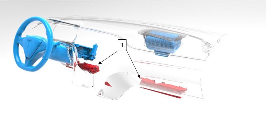
| 1. Side airbag (front row outboard) 2. Side airbag (second row outboard) |
| Front and Second Row Seat Side Airbags |
The side airbags are part of the front and second row seats. The seat side airbags are deployed from the outboard side of the seat, forming a cushion between the occupant and the door, protecting the occupant’s upper torso and pelvis area during a side impact.
Side seat airbags are built into the seat themselves, they are not serviceable. If deployed or damaged the seats will need to be replaced.
Side Curtain Airbagslink
 |
|---|
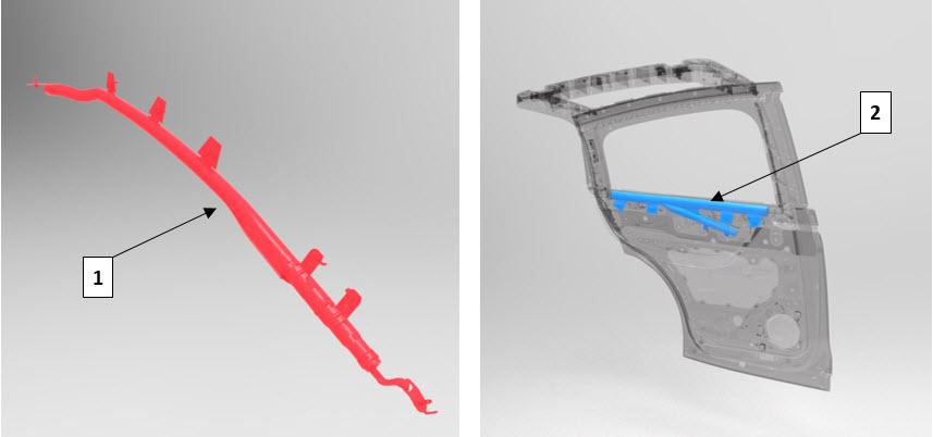
| Side Curtain Airbags |
The side curtain airbags are located near the side roof rails. They inflate over the full area of the front and rear side windows to form a cushion, protecting the occupant’s head from contact with the window frame or pillar(s) in a side-impact collision. The side curtain airbag deploys downwards from the top and drapes over the entire glass area. The side curtain airbags stay inflated for a few seconds after a collision in case the vehicle rolls over.
Knee Airbagslink
 |
|---|
| 1. Knee airbags |
| Knee Airbags |
Knee airbags for the driver and front passenger are located on the lower part of their respective dashboards and are designed to deploy against the occupant’s lower legs, reducing the forward momentum of the lower body during a mid- to high-speed frontal impact. Driver side deployment is dependent on the logic determined by the RCM, and passenger side deployment is dependent on the logic determined by the OCS and the RCM. When deployed, the knee airbag pushes against the occupant's lower legs, contacting them at the knee cap level, cushioning the legs down to the shin and ankle level and holding the occupant properly positioned in the seat.
Steering Columnlink
 |
|---|
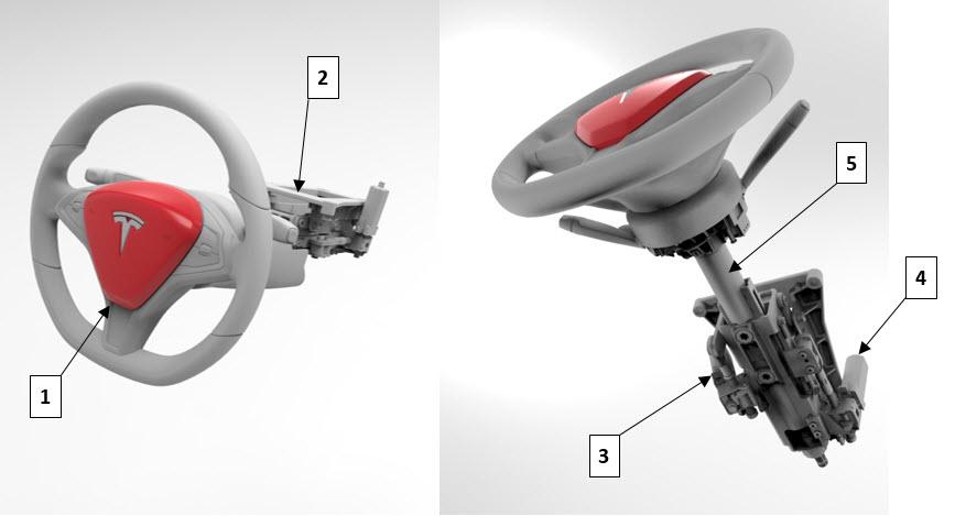
| 1. Driver Airbag 2. Steering column carrier 3. Tilt motor 4. Telescopic motor 5. Steering shaft |
| Steering Column |
The steering column is designed to absorb energy and collapse during frontal collisions, in order to decrease the chance of injury to the driver. The column has 100mm of collapsible travel. A deformable wire adds resistance to the collapsing motion. If the vehicle has been in a collision that caused driver airbag deployment, the column should be inspected to check whether it collapsed.
Warning
The steering column must be inspected whenever the driver airbag has deployed. Refer to BR-16-20-007, "Airbag Component Inspection and Replacement After Deployment, Model X" for inspection instructions.
Clockspringlink
The clockspring is encapsulated into a plastic cassette, contained within the Steering Column Control Module (SCCM). The cassette consists of an outer and inner housing, with integral connectors that contain a flat ribbon flexible cable with four wires carrying out the following functions:
- Positive feed to the inflator module, Stage 1 and 2
- Ground to the inflator module, Stage 1 and 2
Airbag Indicator Lightlink
The airbag indicator light, located in the instrument cluster, is used to notify the driver of TSRS malfunctions and to verify that the RCM is communicating with the instrument cluster. When the vehicle is on and drive rail power is on, the RCM is supplied with positive voltage. The instrument cluster momentarily turns on the airbag indicator light. While the indicator is on, the RCM conducts tests on all TSRS components and circuits.
A TSRS malfunction could result in non-deployment of the airbags or deployment in conditions less severe than intended. Alerts are broadcast on Chassis CAN indicate the failed component in the system. The TSRS airbag indicator remains ON until a successful startup and system check has been completed. Check Toolbox to verify if a certain fault will latch the light on or will allow it to be cleared during a drive cycle.
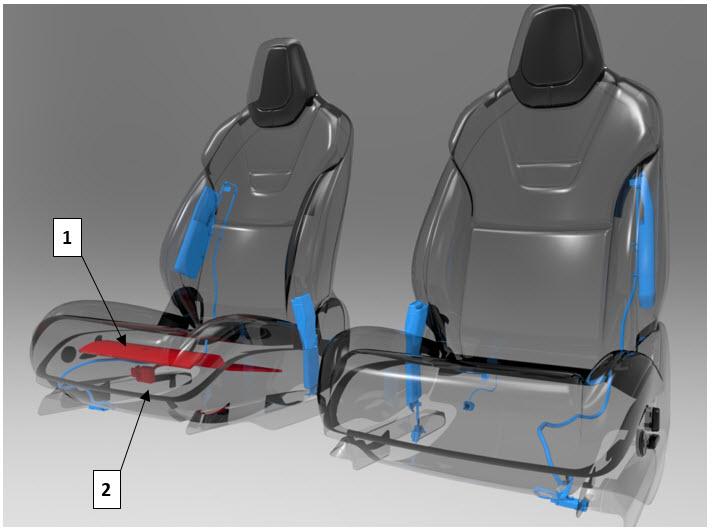
Seat Belt Pre-Tensioner (First and Second Row)link
 |
|---|
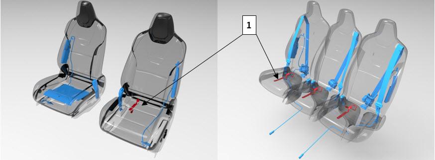
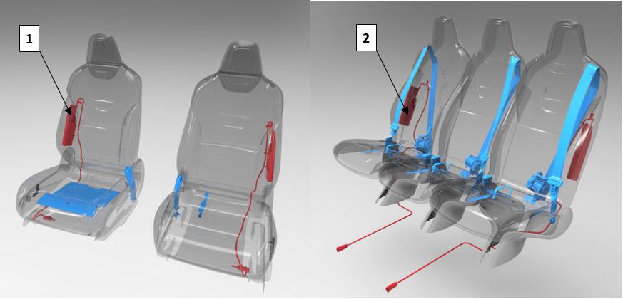
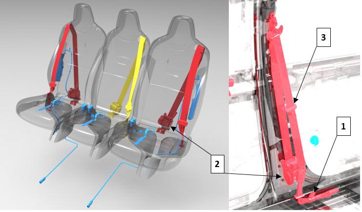
| 1. Lap belt pre-tensioner 2. Shoulder belt retractor and pre-tensioner 3. Seat belt buckle |
| Seat Belt Pre-Tensioner (First and Second Row) |
The driver and first row passenger seat belt pretensioners are a dual pre-tensioner system. The lap belt pretensioners are mounted on the body sill side, and the shoulder belt pretensioners are integral with the retractors. The outboard second row seats each have a single shoulder pre-tensioner. The initiators of all pretensioners are part of the seat belt pre-tensioner deployment loop and always deploy simultaneously.
Anytime an airbag deployment occurs, the seat belt pretensioners are also deployed. These devices are designed to work together to safely absorbed occupant energy. In the case of a rear impact where airbags are not deployed, the pretensioners deployment is responsible for absorbing all the occupant energy. The pretensioners will not be deployed if the corresponding seat belt buckle signal is unlatched. If the signal is not available or faulted at the time of deployment we assume seat belts are buckled and the pretensioners will be fired.
Anytime an airbag deployment occurs, the seat belt pretensioners are also deployed. The RCM directs current through the deployment loops to the initiator. Current passing through the initiator ignites the material in the canister, producing a rapid generation of gas. The gas produced from this reaction deploys the seat belt pretensioners, which remove slack in the lap and/or shoulder belts. The process is one time only and cannot be reversed. The component needs to be replaced after every deployment.
Pedestrian Warning Systemlink
 |
|---|
| Pedestrian Warning Speaker in vehicles built before September 2020 |
 |
|---|
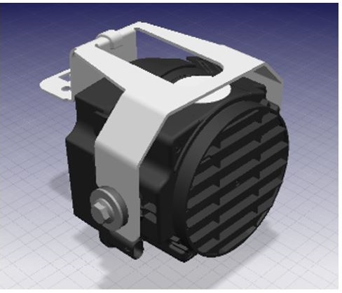
| Vehicles built after September 2020 have a bracket so that the new speaker can fit on the front fascia |
| Pedestrian Warning Speaker in vehicles built after September 2020 |
Functionality and Purposelink
The Pedestrian Warning System (PWS) encompasses a speaker enclosed in a box at the left hand front of the vehicle, located on the front fascia. The PWS is a legal requirement based off region, the specifics of the requirement (pitch of noise, speed of vehicle etc) is dependent on which region the vehicle is located. Electric vehicles traveling at slow speeds must emit a noise to warn pedestrians of motion. As soon as a vehicle is put into gear the speaker emits a noise. Vehicles in the APAC market, not including Japan, have the ability to turn off the PWS.
Drive
The speaker emits a noise while the vehicle is in drive. As the vehicle accelerates, the noise goes up in pitch. Once the vehicle reaches a speed of 30kph/19mph the noise begins to fade out The forward motion noise sounds similar to a spinning fan and Tesla has taken precatuion to minimize the noise for customers inside the vehicle, the intent is that the Pedestrian Warning Speaker is only heard from outside the vehicle.
Reverse
When the vehicle is in reverse, the noise emitted by the PWS needs to be heard at the rear of the vehicle. Due to the fact that the speaker is located at the front of the vehicle, the noise for reverse is increased and can be heard within the vehicle. The sound while in reverse is more a tone. The noise in reverse intentionally sounds different than the noise in drive. No matter what the speed, the PWS will emit a noise while in reverse.
As of September 2020, the United States requires all new electric vehicles be equipped with the Pedestrian Warning System, with the new requirement, Tesla improved the system to be less noticeable for customers within the vehicle. Vehicles built prior to September 2020 have the potential to hear the PWS while within the vehicle.
Communication
The PWS receives messages via the UI. The drive inverter reports the gear and the speed of the vehicle to the gateway. The gateway then communicates this information to the UI where the audio system then transmits the appropriate noise based off these inputs. The audio system in the vehicle includes microphones, the amplifier that then communicates to all speakers. If there are issues with the Pedestrian Warning System, a good first debug step would be to check the other speakers in the vehicle to pinpoint if the issue is with the audio system as a whole or the Pedestrian Warning Speaker.
Serviceabilitylink
Gateway Configurations - pwsSpeakerType - 0 = no speaker - 1 = speaker - 2 = new speaker (as of SEPT2020) - PWSsupported - first 700 MX had a different system so we had to change the harness, only few vehicles have this configuration
Self-Tests - TEST-BASH_SPK_X_PWS-CHECK
This self test simply checks if the speaker is connected to the amplifier.