Doorslink
Last updated: October 20, 2023
Front Door Latchlink
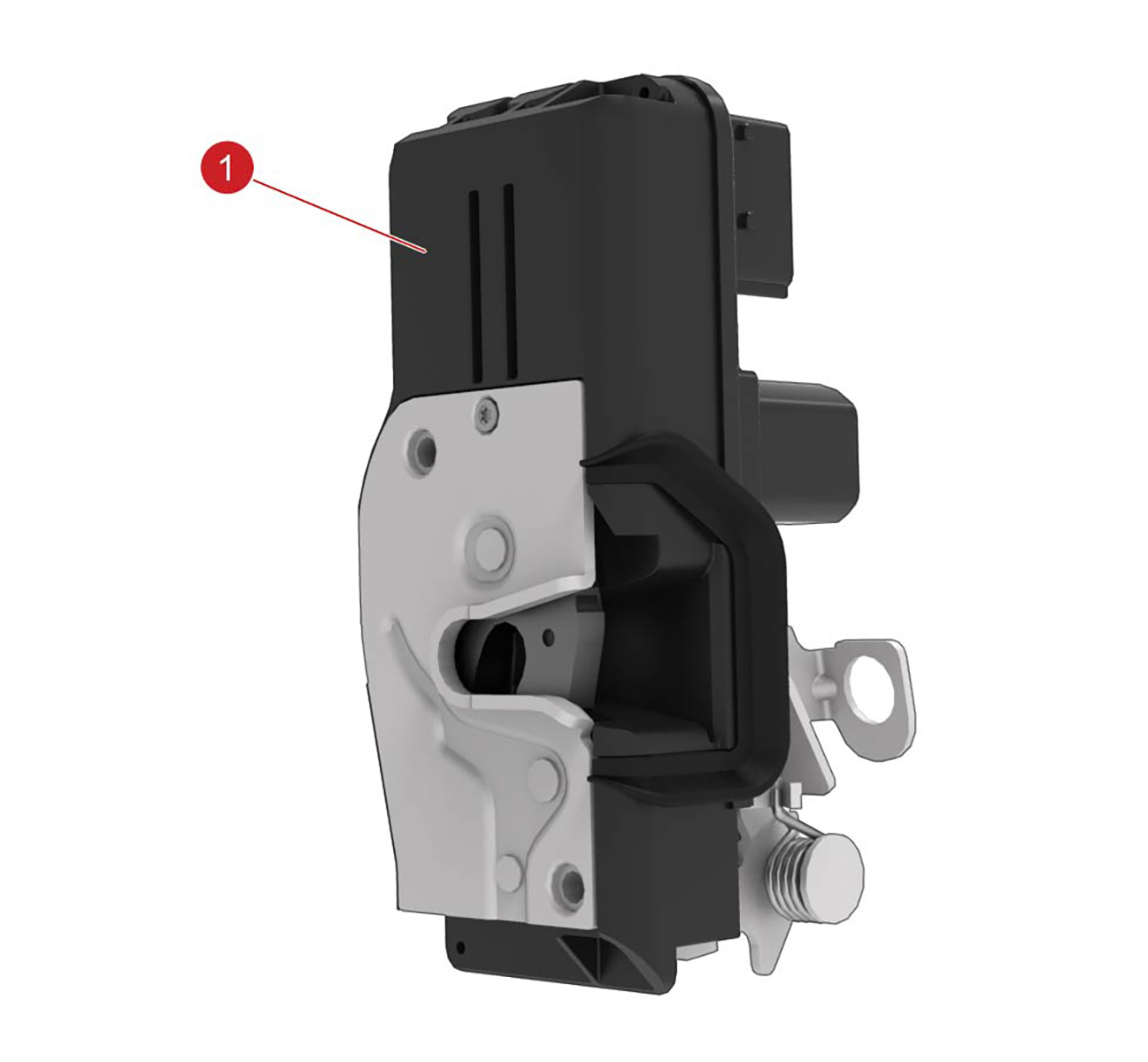
The front door latches are located inside each door.
 |
|---|
| 1. Front door latch |
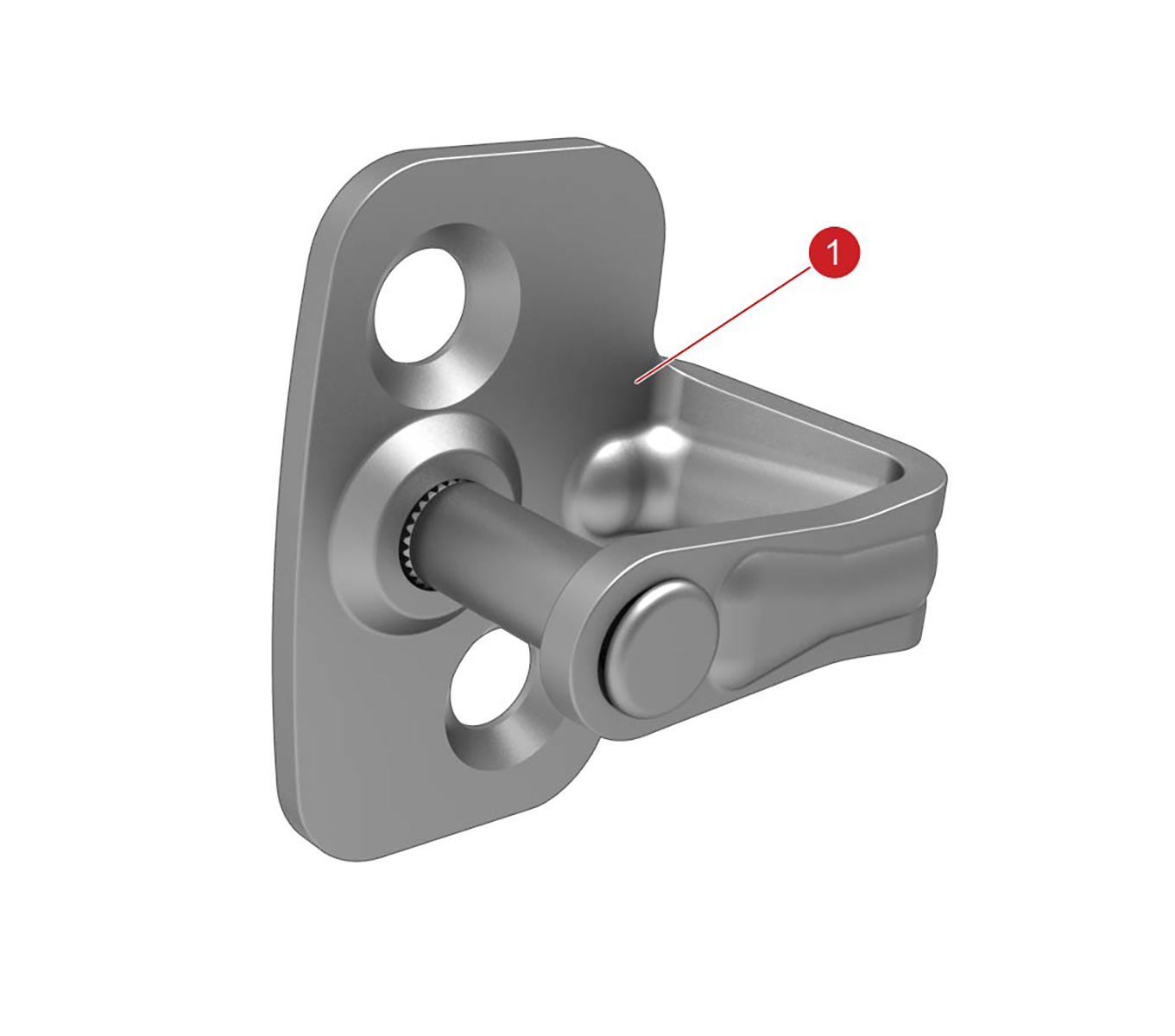 |
| 1. Door latch striker |
The front door latches are located inside each door. The latch is primarily electric, but a cable is connected to the latch from the front door interior release handle to open the door if there is an electrical fault or malfunction.
The front door latch striker is located on the ‘B’ post, and can be adjusted for alignment.
Rear Door Latchlink
 |
|---|
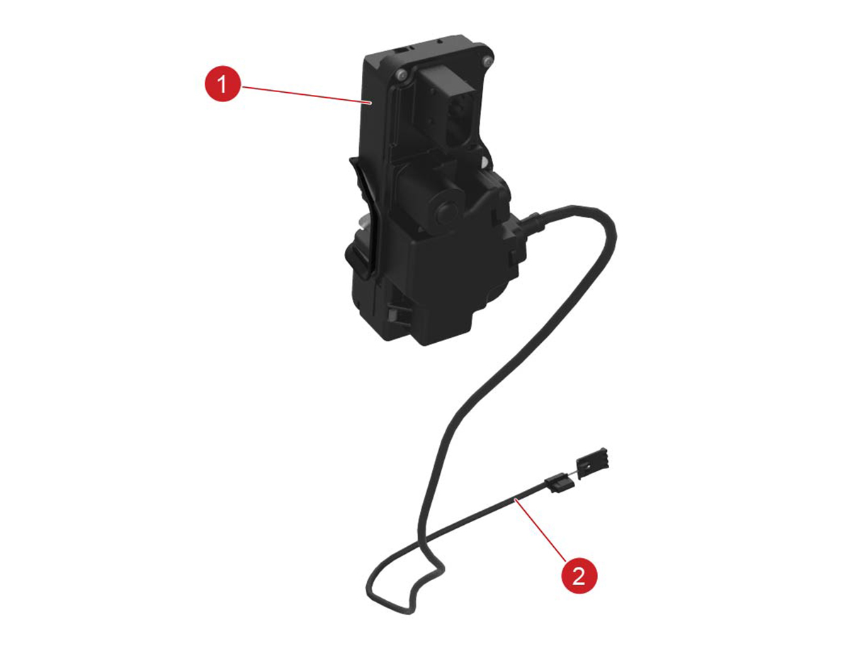
| 1. Rear door latch 2. Release cable |
|
| 1. Door latch striker |
The rear door latches are inside the rear quarter panels. The rear interior door handle electronically operates the latch switch in the rear of the handle.
The rear door latch striker is located on the rear edge of the door. The latch strikers can be adjusted for alignment.
The rear door latches have child locks, which can be enabled and disabled using the touchscreen.
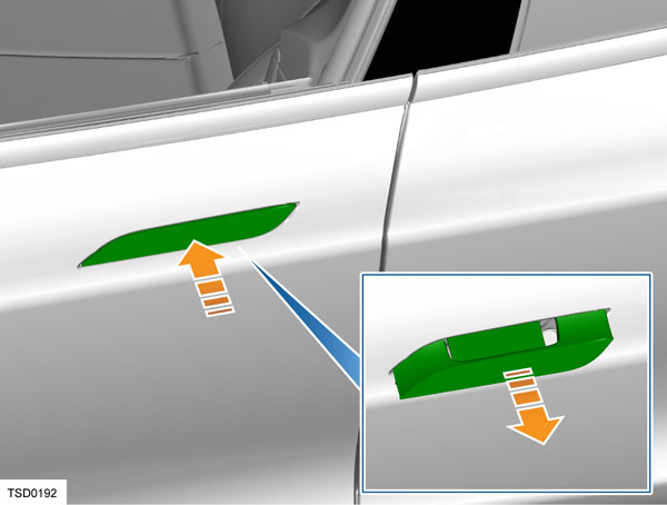
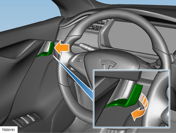
In the event of vehicle electrical malfunction, the rear doors can be opened using the release cables located under the carpet of the rear seat.
- Fold back the panel in the carpet under the seat to access the release cable.
- Pull the release cable towards the center rear seat to open the door.
Door Handleslink
Overviewlink
The exterior door handle sits flush with the door panel when retracted. Upon request, the handles extend out to allow the doors to be opened.
 |
|---|
Model S has electrically actuated exterior door handles that are normally flush with the body, but present themselves for use when needed. When retracted, the exterior door handle is flush with the door panel. Upon request, the handles extend out to allow the doors to be opened. There are multiple ways of extending the exterior door handles:
-
Unlock the vehicle without door handle interaction. This can be done by:
- Double pressing the key fob top button
- Approaching the vehicle carrying the key fob (only if 'Auto-present handles' and 'Passive Entry" is enabled)
- Shifting to Park (only if 'Unlock on Park' is enabled)
- Pressing the Park button again after shifting to Park if 'Unlock on Park' is disabled
- Unlock the vehicle from the MCU
- Use the mobile app to unlock
-
Unlock the vehicle by pressing a front exterior handle while carrying a key fob. Only if "Passive Entry is enabled'. In the past 'Push to Unlock' was optional but has become a standard feature
- Press any exterior door handle while the vehicle is already unlocked
Note
When 'Driver Door Unlock Mode' is enabled, only the driver front door will present instead of all 4 handles.
Note
When 'Passive Entry' is disabled, the vehicle doesn't use the LF antennae. In this situation, it cannot locate a key fob. The vehicle will not unlock when a key is in close proximity, even not when a front door handle is pushed. The only way to unlock a vehicle with Passive Entry disabled, is to physically double-press the top key fob button or to use the mobile app.
The handle is designed so that the present motion is actively achieved using a gear-reduction motor and mechanical linkage, which can overcome resistance from an iced-over handle. When the motor is reversed and removes pressure from the linkage, the handle retract motion is passively achieved using light spring pressure. Door handles automatically retract 60 seconds after the door is closed if they are not pulled. If Model S is still unlocked or a key fob is detected, lightly push a door handle to extend it.
Note
The door handles retract on spring pressure alone. If a hand or other object is in the door handle when the handle retracts, only light pressure is applied. The handle can easily be pulled back out to its fully extended position. This enables the hand or object blocking the handle to be removed.
Note
Lock the Model S using the touchscreen to prevent the door handles from extending.
Identifying Door Handle Generationslink
Refer to the table below for the external and behavioral differences between 1st Generation (Gen1), 2nd Generation (Gen2), 2.5 Generation (Gen2.5) and 3rd Generation (Gen3) door handles.
| 1st Generation | 2nd Generation | 2.5 Generation | 3rd Generation | |
|---|---|---|---|---|
| Handle Presentation Value | 100% | 90% | 90% | 90% |
| Grip Operation | Grip does not noticeably move when pulled | Grip moves remaining 10% when pulled | Grip moves remaining 10% when pulled | Grip moves remaining 10% when pulled |
| Retracted detection | Micro-switch | Micro-switch | Micro-switch | Hall effect sensor |
| Presented detection | Pressure Strip | Micro-switch | Micro-switch | Hall effect sensor |
| Pulled detection | Pressure Strip | Micro-switch | Micro-switch | Hall effect sensor |
| Push-to-Present detection | Push Sensor | Push Sensor | Push Sensor | Hall effect sensor |
| Handle firmware | 0.x.x | 1.x.x | 1.x.x | 2.x.x |
Refer to the Tech Note TN-17-11-001 - "Replacing Model S Exterior Door Handles" for additional information.
Exterior Door Handleslink
1st Generation Door Handlelink
Vehicles manufactured before 9 April 2013 originally were equipped with 1st Generation door handles. Vehicles that had a door handle malfunction with 1st generation handles might have been upgraded to 2nd generation door handles.
The handle uses two pressure sensors. One sensor is located on the retract hard stop, and is used to detect a press on the handle when the user wants it to present. The second sensor is on the present hard stop, and is used for two purposes: to detect when the handle has reached its presented position and stop the motor, or to detect a pull on the handle that indicates a request to open the door. The pressure sensors are inputs to the control module that is built into the handle. The control module processes the inputs and sends out messages on the LIN bus that connects it to the door control module. Also incorporated into the handle is a LED puddle light that illuminates the handle area and the ground below it.
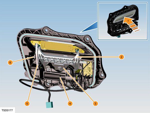 |
|---|
| 1. Outer handle 2. Door handle fork 3. Door press sensor 4. Door handle motor 5. Door handle control link 6. Door handle position switch |
| 1st Generation Door Handle |
 |
|---|
| Push Sensor,1st Generation Door Handle |
 |
|---|
| Push Sensor, 1st Generation Door Handle (Pressure Strip Highlighted) |
Pressing the outer handle applies pressure to the door handle fork, which rests against the door press sensor. This extra pressure to the sensor gives a small resistance change in the circuit that the handle control modules detect. The handle control modules activate the exterior handle motors that extend the exterior handles outward. When the handle linkage makes contact with the pressure sensor, the control module detects the change in voltage from the sensor and stops the motor. Pulling on an exterior handle increases the pressure on the sensor, and the control module monitors the sensor for this increase. When the increase in voltage crosses a calibrated threshold, a door opening request is recognized and sent to the door control module. The door handle module sends a message over the discrete LIN bus to the door control module and, if the criteria for allowing door opening are met, releases the respective door latch assembly from the latched position and allows the door to be opened.
2nd Generation Door Handleslink
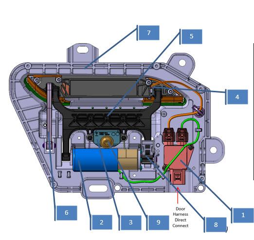
Vehicles manufactured between 10 April 2013 and 16 April 2016 originally were equipped with 2nd Generation door handles. Vehicles manufactured after 16 April 2016 through 24 August 2017 originally were equipped with 2.5 Generation door handles. The differences between the 2nd Generation and 2.5 Generation handle are the carrier, the motor, and the hard back cover.
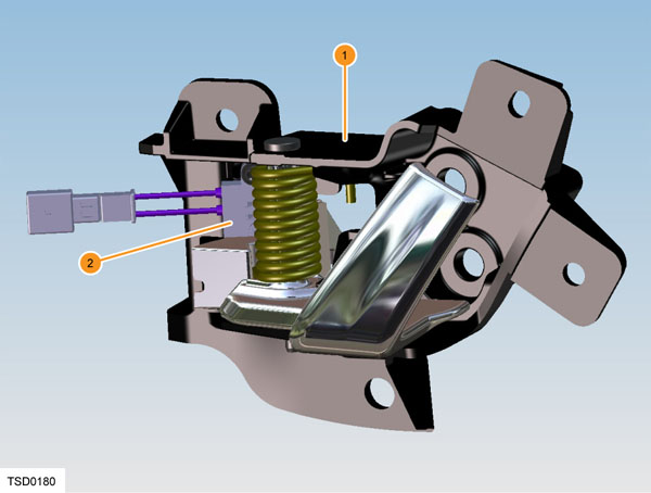
 |
|---|
| 1. ECU 2. Motor 3. Pressure Sensor 4. Present Micro-switch 5. Retract Micro-switch 6. Unlatch Micro-switch 7. LED 8. Handle Fork 9. Hankle Link 10. Carrier 11. Paddle Gear 12. T40 Adjustment Screw |
| 2nd Generation Door Handle, Overview |
The handle uses pressure sensors to detect push-to-present. The pressure sensor is located on the retract hard stop, and is used to detect a press on the handle when the user wants it to present. The pressure sensor is a piezo electric sensor that creates a voltage when touched. These pressure sensors are inputs to the control module that is built into the handle. The control module processes the inputs and sends out messages on the LIN bus that connects it to the door control module. Also incorporated into the handle is a LED puddle light that illuminates the handle area and the ground below it. The door handle motor is a DC motor that is PWM controlled by the ECU. The motor doesn’t have an encoder. Position of the handle is measured by the 3 micro-switches
The door handle has 3 main positions: retracted (0%), presented (90%) and pulled (100%). These positions are measured by micro-switches. Next to the 3 micro-switches, there is a pressure sensor that detects push-to-present.
To start movement from one position to another, the handle needs to be in a known position. This means that if the door handle is in an unknown state it will not move to another state. For example, this could be caused by a not operating as expected micro-switch.
Both door handles on the same side of the vehicle communicate over LIN to their corresponding door module (DDM/PDM). The LIN bus speed is 19.2 kb/s. The door module is the primary node in the LIN communication and the door handles are secondary nodes. The door module sends commands to the door handles and the door handles respond with feedback signals.
The most important command the door module sends to the door handle is ‘Handle Position Command’, which can represent ‘No Change’, ‘Present Handle’ or ‘Retract Handle’.
The door handle receives this command and will actuate the handle accordingly.
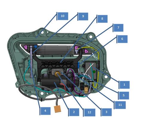
3rd Generation Door Handleslink
Overviewlink
Vehicles manufactured after 24 August 2017 originally were equipped with 3rd Generation door handles. At time of publication, 3rd Generation door handles could only be installed on vehicles with the new style door panel. So, only vehicles with 2.5 Generation door handles can be retrofitted with 3rd Generation door handles. There is no difference between the front door handles and rear door handles. However, the door handles are different for the left-hand and right-hand side of the vehicle.
3rd Generation door handles are fundamentally different from 2nd Generation and 1st Generation door handles. The 3 micro-switches and the push sensor are replaced by a single hall effect sensor, the ECU is external to the handle. and the many connectors are removed and the only necessary connectors are replaced by IPx9 rated automotive connectors.
 |
|---|
| 1. Connector Block 2. Motor 3. Push Block 4. LED 5. Handle Fork 6. Handle Link 7. Carrier 8. Paddle Gear 9. T40 Adjsutment Screw 10. Fork Axle |
| 3rd Generation Door Handle, Overview |
 |
|---|
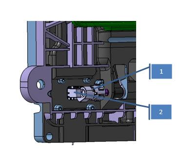
| 1. Magnet Holder + Magnet 2. Hall Effect Sensor |
| 3rd Generation Door Handle, Hall Effect Sensor and Magnet |
 |
|---|
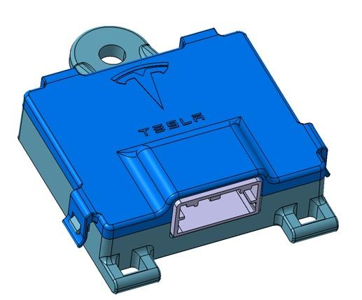
| Door Handle ECU |
Component Detailslink
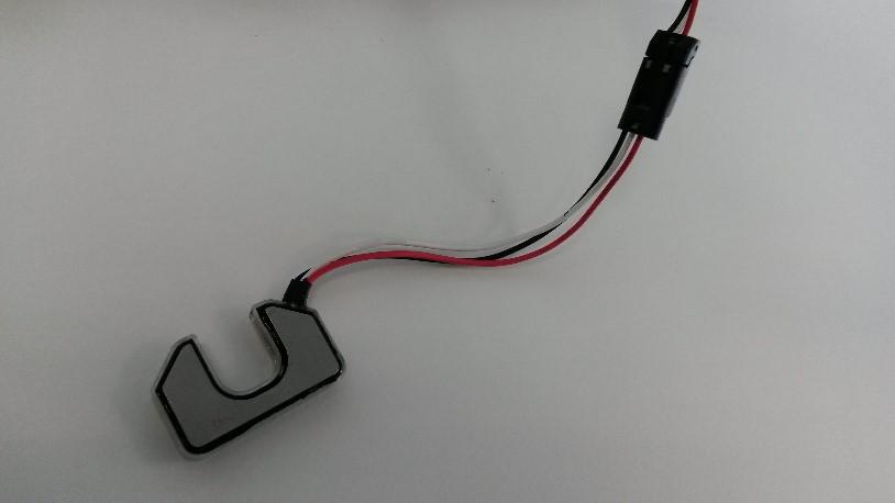
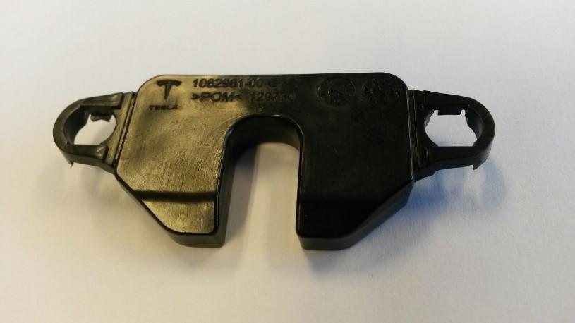
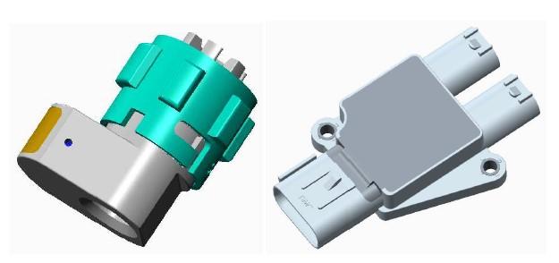
Connector Blocklink
The connector block is located where the ECU used to be on older door handles. The connector block connects the LED and the motor to the vehicle harness. The three connectors are IPx9 rated. The connector block assembly also contains a hall effect sensor. The entire assembly is encapsulated in a low pressure mold to make it watertight. A connector with 6-pins connects to the door harness.
 |
|---|
| Connector Block |
Motorlink
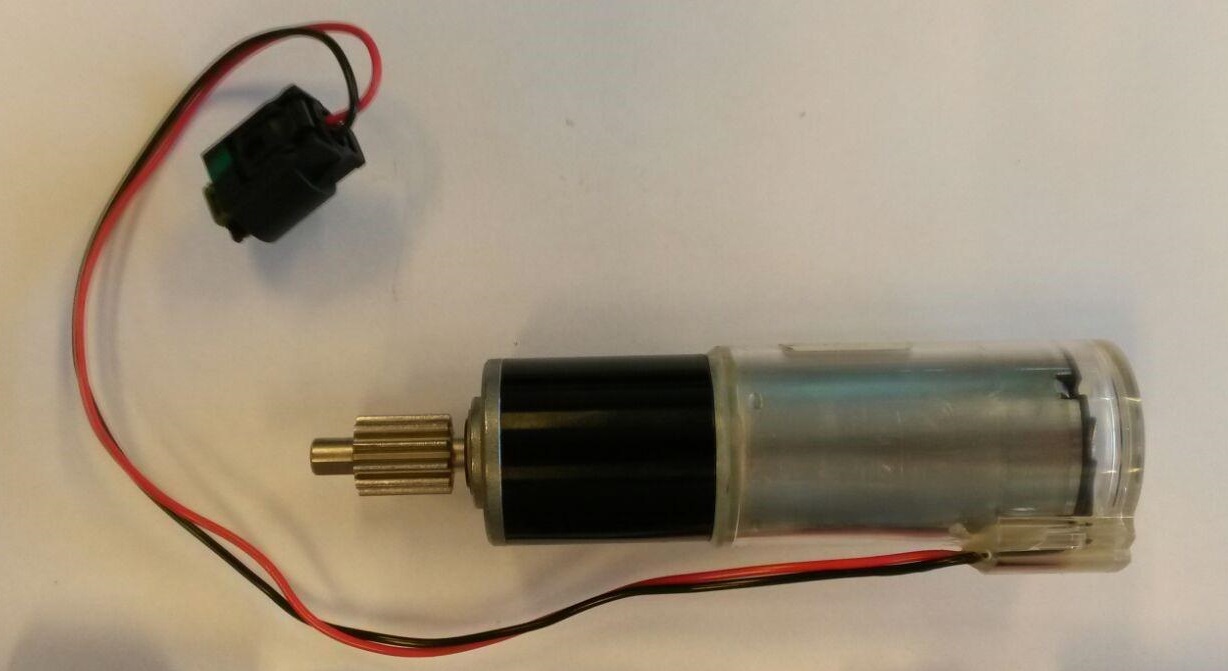
The motor assembly consists of a motor, an adaptor plate, and a 3-stage planetary gearbox. The motor is a DC motor with brushes and 3 pole-pairs. It is PWM controlled by the ECU. The maximum PWM percentage that is applied is 80% (9.6V) but in most cases less voltage is applied. The maximum current is hardware limited to 2.5A but software controlled to a lower limit by the ECU depending on the motion.
 |
|---|
| Motor and Gear Box |
Push Blocklink
The push block replaces the push sensor on earlier door handles. The push block is not a sensor but is just a plastic mold that is a little bit flexible. It basically acts as a spring to allow the handle axle to rotate slightly upon a push-to-present event.
 |
|---|
| Push Block |
LEDlink
The LED is the same as on older door handles. The only difference is the new IPx9 connector that connects it to the connector block. The handle has a LED puddle light that illuminates the handle area and the ground below it.
Carrierlink
At the time of publication, the carrier only fits vehicles built after 16 April 2016.
Magnet Holder and Magnetlink
The magnet is located inside of a holder that is mounted to the handle shaft. Each handle position corresponds to a certain magnetic flux measurement value from the hall effect sensor. After calibration, the door handle can relate the measured value to a door handle position.
 |
|---|
| Magnet |
Hall Effect Sensorlink
The hall effect sensor is the only sensor in the 3rd Generation door handle. It measures magnetic flux of the magnet on the axle shaft. The sensor is encapsulated into the connector assembly.
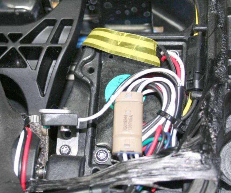
Electronic Control Unitlink
The motor, LED, and hall effect sensor are wired to the ECU which is external to the door handle. It is fitted onto the closeout panel on the dry side of the door.
Operationlink
The door handle has 3 main positions: retracted (0%), presented (90%) and pulled (100%). These positions are measured by micro-switches. Next to the 3 micro-switches, there is a pressure sensor that detects push-to-present.
To start movement from one position to another, the handle needs to be in a known position. If the door handle is in an unknown state, it will not move to another state. For example, this could be caused by a not operating as expected micro-switch.
Both door handles on the same side of the vehicle communicate over LIN to the corresponding door module (DDM/PDM). The LIN bus speed is 19.2 kb/s. The door module is the primary node in the LIN communication and the door handles are secondary nodes. The door module sends commands to the door handles and the door handles respond with feedback signals.
The most important command the door module sends to the door handle is ‘Handle Position Command’, which can represent ‘No Change’, ‘Present Handle’ or ‘Retract Handle’.
The door handle receives this command and will actuate the handle accordingly.
Pinoutlink
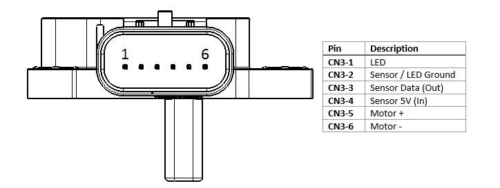 |
|---|
| Pinout, Top |
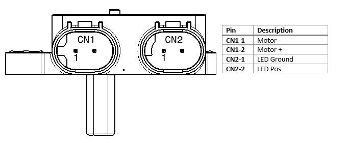 |
|---|
| Pinout, Bottom |
Door Handle Stateslink
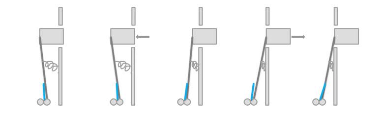
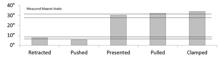
The figure below explains the different door handle states and how they relate to the handle shaft angle. There are 2 angle ranges which are the ‘Retracted’ position and the ‘Presented’ position.
 |
|---|
The table below explains how handle axle shaft angle relates to travel percentage, to motor state and to hall sensor value.
 |
|---|
Calibrationlink
Since the 3rd Generation door handle has continuous position feedback by means of a hall effect sensor, it needs a calibration routine like any other position controller in the vehicle (Falcon Doors, seat track positions, active spoiler, etc.).
The calibration routine cycles through the entire range of positions and match the position measurement values with known fixed positions (latched position for the Falcon Doors, hall sensor for seat track position, and hall sensor for the spoiler).
For the 3rd Generation door handle, these positions are the clamped and the retracted positions.
- Clamped: This is the most outward position of a door handle. The motor pushes the handle outwards against its mechanical end where current starts to rise. This position is considered 100% handle position.
- Retracted: This is the most inward position of a door handle. It is the point where the 'push-to-present block' starts to touch the T40 screw. This is also the point where the hall effect sensor doesn't see a change in angle while the motor still spins. This point is considered 0% handle position.
Once the handle knows which hall effect sensor readings correspond to 0% and 100%, it knows all other position in between, e.g. the presented position is considered 90% handle position.
When retracting, the motor actually stops a little later than the 0% position (~ -5%) to leave a little bit of room to push the handle.
The handle is self-calibrating in the vehicle. This way the handle can compensate for carrier and door sheet metal warpage.
Sleep Modelink
The microcontroller will go to sleep if a sleep command is sent over LIN, or if there is no LIN activity and the door handle is in the retracted position. When asleep, the microcontroller can be awakened by LIN activity or by a handle push. By periodically waking up, sampling the sensor, then going back to sleep (at a rate of 10Hz), the microcontroller is able to detect the handle position to register the pushes. The hall effect sensor is switched off while the microcontroller is asleep and turned on when it wakes to take samples.
Interior Door Handleslink
 |
|---|
To operate the interior door handles, pull the lever.
The front door interior release handles have a switch that closes when the handle is pulled. This sends a signal to the door control module to request a door opening. If the switch malfunctions or power is not present, the release cable acts as a mechanical backup and releases the latch.
 |
|---|
| 1. Rear door handle 2. Release switch |
The rear door interior release handles have a switch that closes when the handle is pulled. This sends a signal to the door control module to request a door opening. If the switch malfunctions or power is not present, the door can be opened using the manual release cable. A pull tab is located behind a flap in the carpet at each outboard seating position.
Note
Enabling the child-protection lock prevents door opening from the rear door interior release handles. The only exception is in the event of an airbag deployment, which unlocks all doors and overrides the child-protection locks. The manual release cables open the rear doors regardless of the state of the child-protection lock. Note: If the doors are locked and the child-protection lock is disabled, a single pull on the rear door interior release handle unlocks that door. A second pull opens the door.