Drive Unitlink
Last updated: May 11, 2024
Acronymslink
| Acronym | Term |
|---|---|
| ABS | Anti-lock Braking System |
| C1IM | Cybertruck Single Motor Drive Unit, Induction |
| C1PM | Cybertruck Single Motor Drive Unit, Permanent Magnet |
| C2IM | Cybertruck Dual Motor Drive Unit, Induction |
| DFLKx (x = F/R) | Differential Locker ECU (Front/Rear) |
| DI | Drive Interface |
| DIx (x= F/R/REL/RER) | Drive Inverter (Front/Rear/Rear Left/Rear Right) |
| DIG | Drive Interface Gateway |
| DSP | Digital Signal Processor |
| DUx (x = F/R/REL/RER) | Drive Unit (Front/Rear/Rear Left/Rear Right) |
| EEPROM | Electrically Erasable Programmable Read-only Memory |
| GDIC | Gate Drive Integrated Circuit |
| IR sensor | Infrared temperature sensor |
| GPO | Graceful Power Off |
| MOSFET | Metal-oxide-semiconductor Field-effect Transistor |
| OPC | Oil Pump Controller |
| PCBA | Printed Circuit Board Assembly |
| PM | Pedal Monitor (Vehicle Powertrain System Monitor) |
| PMx (x = F/R/REL/RER) | Propulsion Monitor (Front/Rear/Rear Left/Rear Right) |
| PM/PMaSRM | Permanent Magnet Motor Type (aSRM = asynchronous reluctance motor) |
| 2PO or 2PD | Two Phase Open or Two Phase Disconnect pyrotechnic fuse |
| SDC (F/R/REL/RER) | Secondary Disconnect Controller (Front/Rear/Rear Left/Rear Right) |
| SOPT | Switch off Path Test |
| TPAK | T = Tesla, PAK = package. Tesla designed package power semiconductor |
| VDC | Vehicle Dynamic Control |
Danger
Obey all high voltage safety requirements when servicing drive unit components. The drive inverter contains up to 560uF of internal capacitance, enough to be lethal if shocked. Always use a multimeter to confirm that high voltage potential is not present on the DC input connector of the drive inverter.
Overviewlink
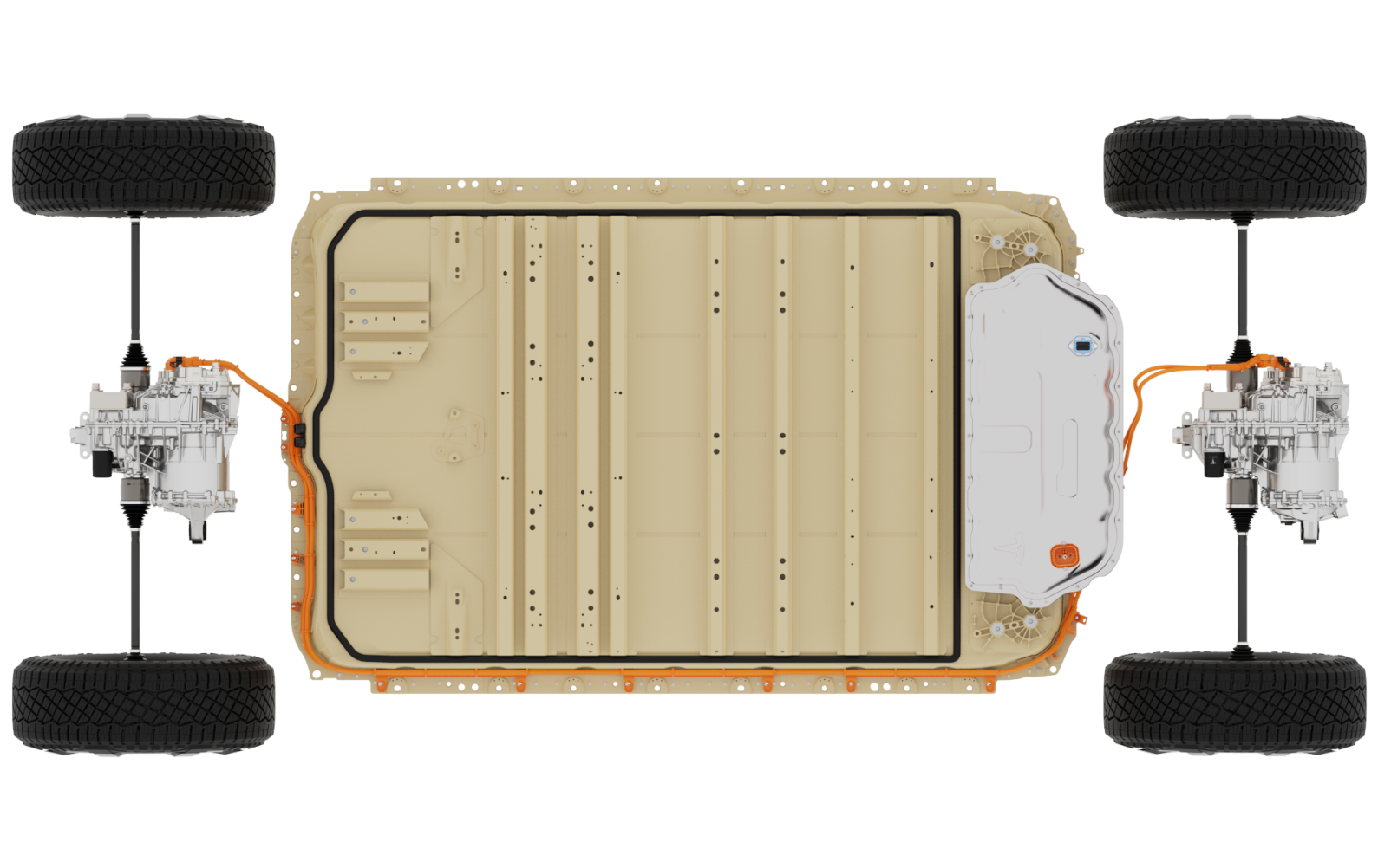
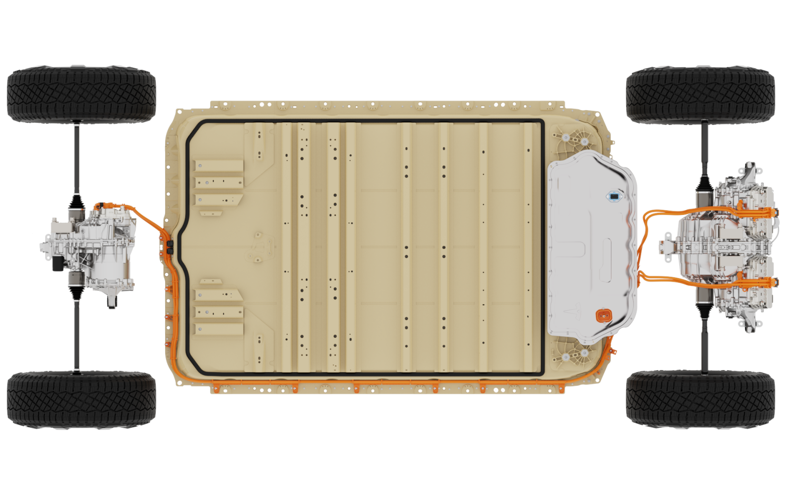
The motor, gearbox, and drive inverter make up the drive unit assembly. The primary function of the vehicle drive unit is to convert electrical energy from the high voltage battery into mechanical energy in the form of wheel rotation. This is done through the interaction between the motor's magnetic field and electric current in the copper winding to generate torque.
Drive units are secured to the vehicle by three mounts in order to resist axial and rotational forces. Torque is transmitted to each wheel via half shafts connected to the drive unit output flanges. Each drive unit gives motion to the wheels in the respective axle. The drive units are not mechanically connected to each other.
Specificationlink
Dual Motor Configuration
 |
|---|
| Drive Unit | #of Motors | Motor Type | Inverter Type | Gear Ratio | Differential Locker | Oil Pump |
|---|---|---|---|---|---|---|
| Front Drive Unit (C1IM) | 1 | Induction Rotor | 850V MOSFET 4DI | 15:1 | Long Range Only | Dual-Gerotor 48V |
| Rear Drive Unit (C1PM) | 1 | Permanent Magnet Rotor | 850V MOSFET 4DI | 15:1 | Long Range Only | Dual-Gerotor 48V |
Tri-Motor Configuration
 |
|---|
| Drive Unit | #of Motors | Motor Type | Inverter Type | Gear Ratio | Differential Locker | Oil Pump |
|---|---|---|---|---|---|---|
| Front Drive Unit (C1PM) | 1 | Permanent Magnet Rotor | 850V MOSFET 4DI | 15:1 | Yes | Dual-Gerotor 48V |
| Rear Drive Unit (C2IM) | 2 | Induction Rotor | 850V MOSFET 4DI | 15:1 | No | Dual-Gerotor 48V |
 |
|---|
| Drive Unit: Single Motor |
 |
|---|
| Drive Unit: Dual Motor |
Drive Inverterlink
Specificationlink
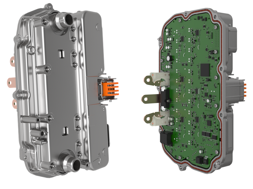 |
|---|
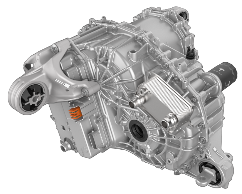
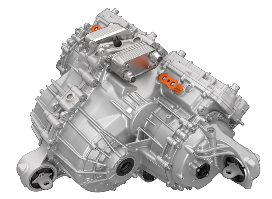
| 4DI Drive Inverter |
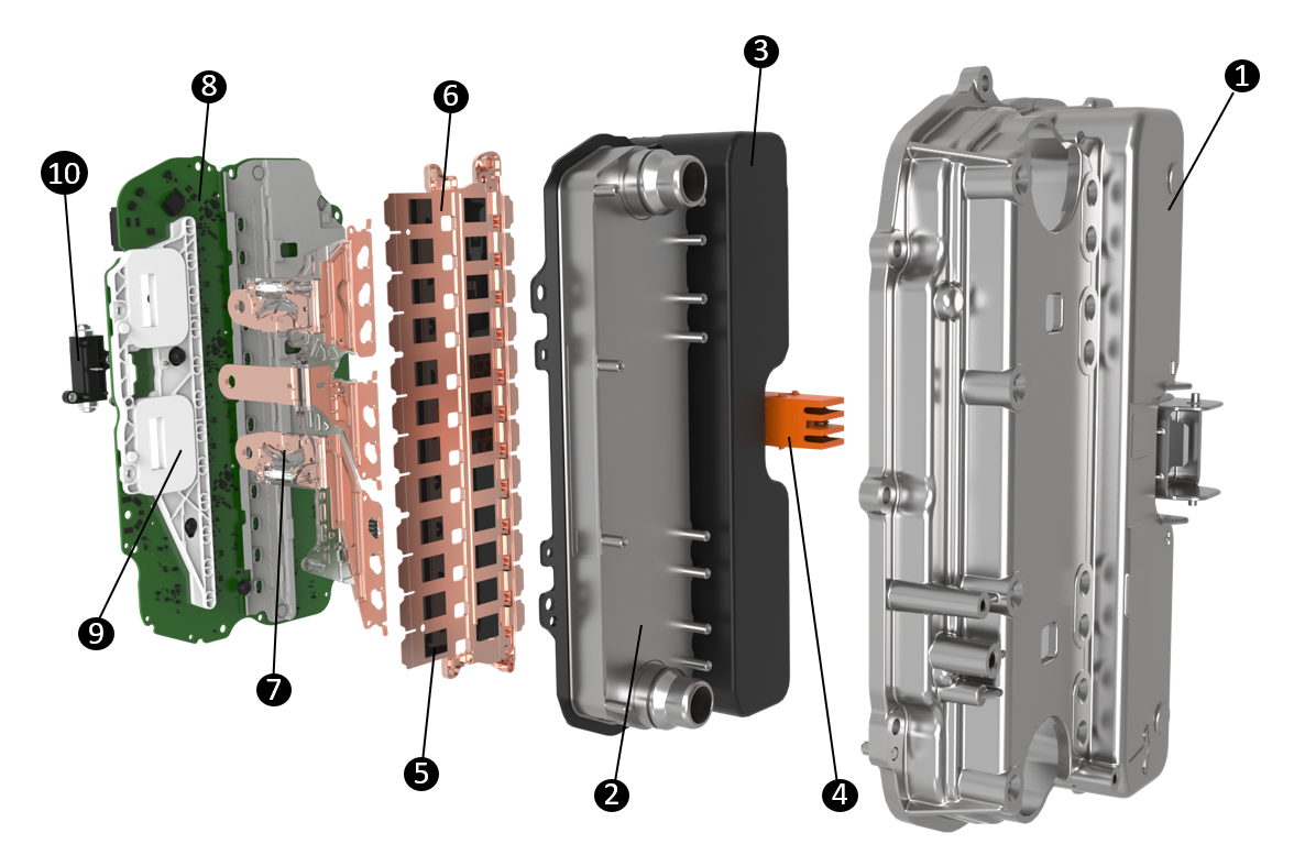 |
|---|
| 4DI Drive Inverter |
| 1. Inverter Case 2. Inverter Heatsink w integrated Coolant Ports 3. DC Link Capacitor 4. HV Header 5. Metal-oxide-semiconductor field-effect transistor (MOSFET) 6. Busbars 7. 3-Phase Bus Bars (connect inverter to stator) 8. Inverter PCBA 9. Current Sensors 10. Two Phase Open (2PO) Pyro |
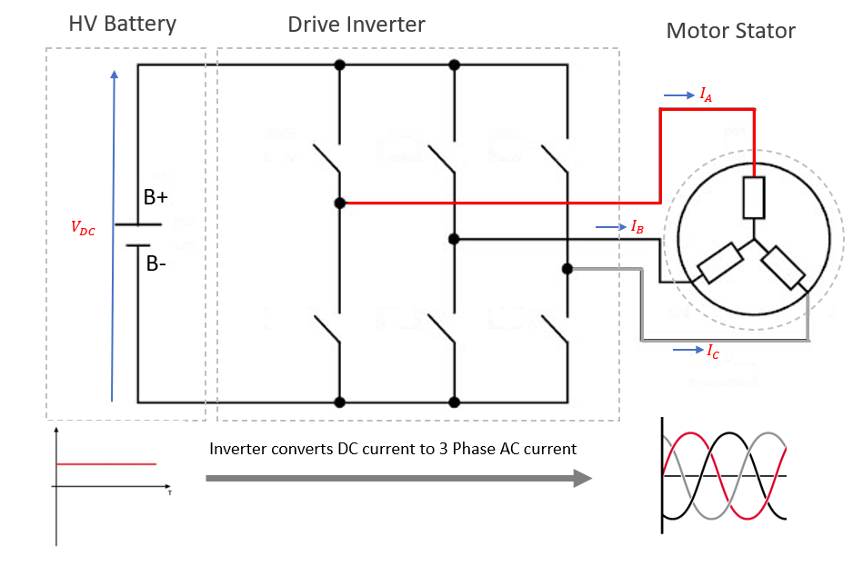
Operationlink
The drive inverter converts Direct Current (DC) electricity from the high voltage battery pack into three-phase Alternating current (AC) electricity required to drive the motor. The current wave forms are 120 degrees out of phase with each other, which creates a rotating magnetic field in the stator.
In an induction motor, the rotating magnetic field in the stator induces an electric current in the rotor. The interaction of these two magnetic fields creates torque, which causes the motor to spin.
In a permanent magnet motor, the permanent magnets inside the motor have a fixed magnetic field. The interaction of this fixed magnetic field with the rotating magnetic field in the stator creates torque.
The speed of both types of motors depends on the frequency of the AC electricity supplied by the inverter. The torque produced by both types of motors depends on the amplitude of the AC electricity. In a permanent magnet motor, the torque also depends on the electrical angle between the magnetic field of the stator and the permanent magnets.
Drive Inverter and Drive Interfacelink
Drive Inverter is the primary torque production controller. Drive Inverter can be unit level, located on the printed circuit board of the drive inverter assembly, or it can be system level, located in the VCLEFT. System level controller is referred to as the Drive Interface.
Drive Interface is responsible for sending appropriate torque commands to front and rear drive units based on the external inputs it receives from the UI, the gear selector, the accelerator pedal, and the brakes system. Drive Interface also handles system level functionality like drive gear management, cruise control, traction control, vehicle dynamics etc.
The unit level Drive Inverter receives torque requests from the Drive Interface and provides a Pulse Width Modulation (PWM) signal to the power stage electronics in order to generate three-phase AC power that is needed to drive the motor. It is also responsible for overall motor controls, fault handling, and unit protections.
Pedal Monitor and Propulsion Monitorlink
The pedal monitor is a safety controller that ensures the motor torque output matches the driver's request. Its primary function is to continuously monitor the DI torque production. If the torque deviates from the Pedal Monitor's calculation, the Pedal Monitor will intervene and cut torque.
Pedal Monitor can be unit level, located on the printed circuit board of the drive inverter assembly, or it can be a system level monitor, located in the VCLEFT. System level controller is referred to as the Propulsion Monitor.
Propulsion Monitor is responsible for monitoring the overall torque production of the vehicle. It also verifies that the drive gear set by Drive Interface is in agreement with the gear qualified by Propulsion Monitor. If there is a disagreement, Propulsion Monitor can command DI to enter neutral or park gear depending on vehicle speed.
Gate Driver and Package MOSFETlink
The gate driver integrated circuit (GDIC) is a specialized electronic circuit part of the drive inverter PCBA that controls the switching of high-power semiconductor devices (MOSFETs). The gate driver's primary function is to convert the low-voltage control signals generated by the DIx chip into the higher voltage levels needed to activate the MOSFETs effectively.
MOSFETs are semiconductor devices utilized as high voltage switches. MOSFETs control the current flow from the battery to the motor, essentially acting as the gatekeepers of power. By adjusting the voltage applied to their gate terminals, MOSFETs can rapidly turn on and off, allowing precise control over the amount of power delivered to the motor. This control determines crucial motor characteristics such as speed, torque, and direction of rotation. The gate driver's role is to ensure that these MOSFETs switch accurately and efficiently, translating the control commands into the necessary voltage signals that manipulate the MOSFETs' operation for optimal motor performance.
Rapid switching of MOSFETs at the appropriate frequency and pattern, convert the DC voltage from the battery into an AC waveform that drives the motor. This voltage conversion is achieved through a technique called Pulse Width Modulation (PWM).
 |
|---|
| DC to AC power conversion |
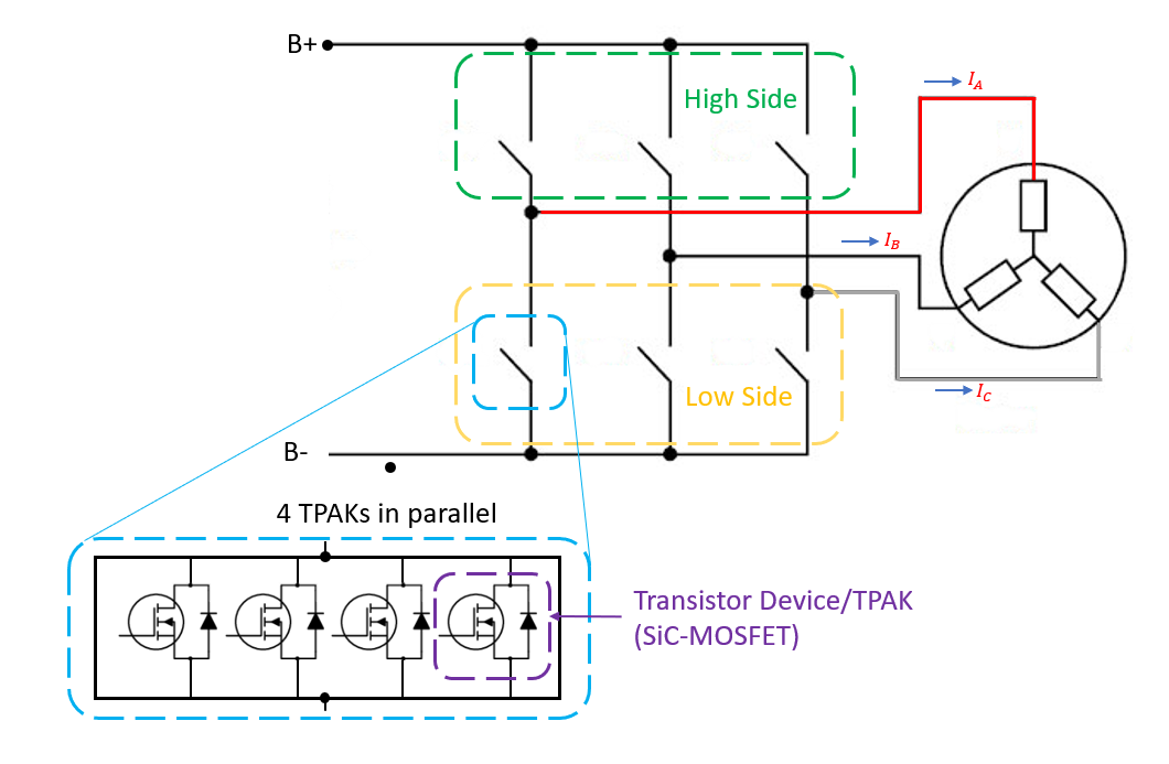 |
|---|
| High Side/Low Side TPAKs |
Communicationlink
Specificationlink
 |
|---|
| Drive Inverter Communication Architecture |
 |
|---|
| Harness Side Drive Inverter Logic Connector |
| Pin | Name | Notes |
|---|---|---|
| 1 | ||
| 2 | CAN_N_IN | Primary CAN bus input (N), connected internally to CAN_N_OUT. Unterminated. |
| 3 | LV_POWER_IN | Switched 48V power from VCLEFT |
| 4 | ||
| 5 | ||
| 6 | ||
| 7 | RES_SIN_N | Twisted pair with Resolver Sine +. Connects to resolver on drive unit assembly. |
| 8 | RES_COS_P | Twisted pair with Resolver Cosine -. Connects to resolver on drive unit assembly. |
| 8 | RES_COS_P | Twisted pair with Resolver Cosine -. Connects to resolver on drive unit assembly. |
| 9 | ||
| 10 | OIL_PUMP_LIN_1 | Oil pump LIN communication. 15V rail powering LIN transceiver. |
| 11 | CAN_P_TERM | Connect to CAN_P_OUT to terminate bus. |
| 12 | CAN_P_IN | Primary CAN bus input (P), connected internally to CAN_P_OUT. Unterminated. |
| 13 | GDN_IN | Ground |
| 14 | CAN_N_OUT Passthrough | Internally connected to CAN_N_IN. Loops to CAN_N_TERM to terminate bus. |
| 15 | CAN_P_OUT Passthrough | Internally connected to CAN_P_IN. Connect this pin to CAN_P_TERM to terminate bus. |
| 16 | RES_EXT_N | Twisted pair with Resolver Excitation +. Connects to resolver on drive unit assembly. |
| 17 | RES_SIN_P | Twisted pair with resolver Sine -. Connects to resolver on drive unit assembly. |
| 18 | ||
| 19 | ||
| 20 | ||
| 21 | CAN_N_TERM | Internally connected to CAN_N_OUT. Loops to CAN_N_OUT to terminate bus. |
| 22 | ||
| 23 | ||
| 24 | ||
| 25 | ||
| 26 | RES_EXT_P | Twisted pair with Resolver Excitation -. Connects to resolver on drive unit assembly. |
| 27 | RES_COS_N | Twisted pair with Resolver Cosine +. Connects to resolver on drive unit assembly. |
| 28 | ||
| 23 | ||
| 23 |
Note
All pins are gold plated and sized the same: 0.64x0.64FS.
Operationlink
The Drive Interface and Propulsion monitor are located in the VCLEFT. The accelerator pedal has two dedicated signal lines directly to the Drive Interface. The rest of the inputs from external ECUs, such as the brakes system, UI, and gear selector, are done over Etherloop.
The torque commands from the Drive Interface to the individual front and rear Drive Inverters are sent via independent private CAN buses. In the three-motor configuration, the rear drive inverters share a single bus. In vehicles equipped with the differential locker, it is important to note that the CAN communication passes through the Differential Locking Actuator (DFLK) PCBA. If the DFLK connector or PCBA is compromised, it is possible for CAN signals to not transmit to/from the respective inverters.
Fault Protectionlink
The inverter fault monitoring uses a range of sensors to protect the inverter and motor hardware and provide the most desirable outcome for the driver.
Switch-Off Path Test (SOPT)link
The switch-off path test is run on every Drive Unit power up to test the functionality of the system responsible for safely shutting down the unit torque production. This test ensures that the shutdown process is executed correctly and reliably, preventing any unintended operation or potential damage while in drive. A non-torque-producing current is sent from the Drive Inverter (DIx) and subsequently shut down by the Propulsion Monitor (PMx) to validate proper operation. The test is twofold, ensuring that drive unit gate drive circuitry is healthy and can generate current and that Propulsion Monitor has full authority over the Drive Inverter.
Serviceabilitylink
Alerts The following alerts will be present during a drive unit power up if the SOPT test fails. Persistent SOPT are usually indicative of gate drive circuit failures or other internal faults like shorts. Looking at alert payload is not required.
- DIX_a024_selfTest - SOPT test failure reported by the DI
- PMX_a033_selfTest - SOPT test failure reported by the PM
Safe Statelink
A motor inverter safe state is a predetermined and controlled mode that is engaged when the drive inverter encounters abnormal or hazardous operating condition. It actuates the low side and highs side switches (MOSFETs) to the best possible outcome to prevent propagating failures. Any torque requests are overridden during Safe State.
| Safe State Type | Low Side Switch State | High Side Switch State | Safe State Application Triggers |
|---|---|---|---|
| None | Normal | Normal | No safe state applied. Normal Drive Inverter operation |
| All-Off | Open | Open | GDIC Fault, Phase Overcurrent, Desaturation, Uncontrolled Regen |
| Low Side 3 Phase Short (LS-3PS) | Closed | Open | Bus Overvoltage, Loss of LV, Pedal Monitor Torque Intervention. May also be applied per the current observer's recommendation |
| High Side 3 Phase Short (HS- 3PS) | Open | Closed | Not automatically applied but can be applied as a result of the current observer's recommendation. |
Current Observerlink
Current observer is triggered following a Safe State application (or any change in Safe State thereafter). The current observer will recommend a new Safe State based on its observation.
If the current observer does not detect any hardware issues, it will recommend the Safe State to return to None, and a retry is attempted.
MOSFET Desaturationlink
Saturation voltage is the voltage drop across the MOSFET when current is flowing through it. During nominal operation, the resistance loses are dissipated in the form of heat through the inverter heatsink and into the coolant loop. If the voltage drop across the MOSFET increases beyond the allowed threshold, this is known as desaturation. This typically occurs in the event of a short circuit, where unexpectedly high currents are flowing through the MOSFET. If not controlled quickly, the MOSFET can overheat and fail.
A desaturation fault detection provides protection against short circuit events by turning off the MOSFET when the saturation voltage exceeds maximum limit.
Two-Phase Open (2PO)link
Overviewlink
Cybertruck uses one permanent magnet drive unit either on the front or rear depending on the vehicle configuration. When the wheels spin, the magnets generate a voltage inside the motor. This voltage needs to be controlled even if the torque command is zero. The drive inverter stops switching (hibernates) during normal operation only if the drive torque command is zero, the waste heat command is zero, and the speed is low enough that the voltage in the motor will not induce uncontrollable deceleration. This voltage needs to be controlled even if the drive unit is in a fault state until the vehicle comes to a full stop. For this reason, in case of semiconductor (TPAK) failure, such as single or double phase shorts, the inverter deploys the two-phase open pyro to physically break the connection on two of the three phases. This disconnects the inverter and high voltage battery from the motor and protects against high voltage battery shorts and high voltage battery pyro deployment. The inverter then checks that the two-phase open deployed successfully and the vehicle is able to continue driving on the remaining drive units.
For cases where DIx chip is unavailable or unable to deploy the pyro, a secondary controller ECU (SDCx) was introduced as a backup actuation method for the pyro. See Secondary Disconnect Controller (SDC) section below.
Operationlink
 |
|---|
| 1. Two-phase open pyro device 2. Phase lug breakaway points 3. Fuses |
| Two Phase Disconnect Pyro Device |
Secondary Disconnect Controller (SDC)link
Specificationslink
 |
|---|
| 1. Secondary Disconnect Controller |
Operationlink
Secondary Disconnect Controller (SDC) is a fallback controller responsible for actuation of the two-phase open (2PO) pyrotechnic fuse inside the drive inverter when the DI chip is unavailable or unable to do so. Some conditions may include:
- Unintended reset of the DI.
- Abrupt loss of mid-voltage power to DI.
- Uncontrolled regenerative braking torque caused by towing abuse (high speed wheels on the ground towing) with DIx chip unpowered.
- Other DI chip or board level failures.
SDC can trigger the 2PO pyro to prevent further propagation of the fault and damage to upstream components in the HV circuit. It is powered by three redundant power sources supplying 5V for reliable operation under various fault conditions:
- Mid voltage - from the vehicle mid voltage circuit.
- DC high voltage - from the high voltage battery.
- Rectified back electromotive force (emf) DC high voltage - energy produced by the motor while vehicle is coasting.
The SDC cannot be repaired or replaced independent of the drive inverter as it is part of the drive inverter PCBA.
Serviceabilitylink
Alerts The following alerts can be used to quickly identify Drive Inverter hardware faults:
- DIx_a156_currentObserver -This alert is triggered when the current observer is executed. The payload can tell:
- a156_initialSafeState - Initial Safe State at time of observation.
- a156_safeStateRecommend - Recommended Safe State based on observation.
- a156_observation - The observed hardware fault.
- DIx_a244_mechSafeStateApplied - Triggered when 2PO pyro is triggered (will not trigger again).
- DIx_a244_postShortTestFailed - The 2PO pyro has triggered if = 1.
- DIx_a015_mechSafeStateAnomaly will be present on every power up if the 2PO pyro was triggered.
- DIx_a00x_hwPhaseXgateDrive - Indicates whether there was a desaturation event detected on high side (a00X_desat_H) or low side (a00X_desat_L).
Note
The shorted MOSFET is usually on the opposite side of the MOSFET reporting desaturation.
- SDCx_a006_pyroTriggered - SDC triggered the 2PO pyro. This will only show at time or when triggered.
- SDCx_a007_faultCurrentsDetected - Abnormal currents are detected but does not necessarily trigger 2PO pyro. If DI is also MIA, it will trigger pyro.
Limp Modelink
Similar to drive inverter fault protection, Limp Mode is intended to protect the vehicle hardware when a fault is detected. The vehicle's performance is intentionally constrained to a basic level, allowing the driver to navigate to a safe location for inspection or repair. This mode can involve reducing power output, limiting speed and/or acceleration, and displaying warning indicators and speed limit to alert the driver of the problem. This can be limited to an individual drive unit (unit limp) or across a vehicle powertrain system (system limp).
If the system is confirmed to have fully recovered, the restrictions imposed during limp mode are lifted, allowing the vehicle performance to return to normal.
Serviceabilitylink
Alerts
- DIx_a062_systemLimpMode - Indicates a system limp mode, meaning there was a fault detected somewhere in the powertrain system.
- DIx_a062_limpReason - Shows which condition caused the system limp.
- DIx_a126_limpMode - Indicates a unit limp mode, meaning there was a fault detected by the unit.
- DIx_a126_limpReason - Shows which condition caused the unit limp.
Note
There are limp reasons that may require further investigation. Do not indicate a fault with the unit reporting it. Some examples are:
- DI_LIMP_TRQCMD_VALIDITY_UNKNOWN - Indicates a missing or invalid torque command from the Drive Interface.
- DI_LIMP_PMREQUEST - Indicates limp mode was requested by the PM/PMx node. Review of the PM/PMx node alerts will show the cause for the limp request.
Motorlink
The stator and rotor comprise the core elements of the motor assembly responsible for the conversion of electrical energy into mechanical motion. The stator (the stationary component) features wound copper bars that carry alternating current, generating a rotating magnetic field. Positioned within this magnetic field, the rotor (the rotating component), is constructed with conductive elements that induce electromagnetic forces, resulting in rotational motion. This interaction between the stator's magnetic field and the rotor's response creates torque. Control systems meticulously regulate the electrical current supplied to the stator, ensuring precise control over the speed and direction of the rotor.
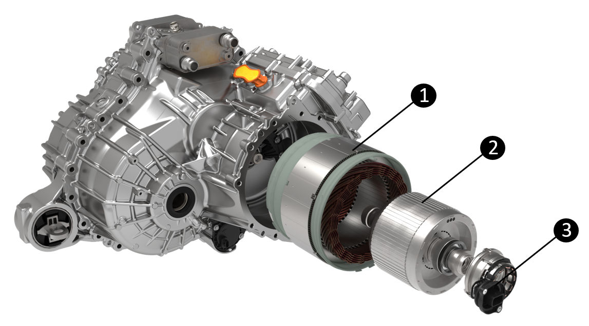 |
|---|
| 1. Drive Unit Stator 2. Drive Unit Rotor 3. Drive Unit Resolver |
| Motor Assembly (Induction Motor shown) |
Resolverlink
A resolver is a type of electrical sensor used to measure the position and speed of the drive unit rotor. Unlike the encoders which are speed sensors, the resolver directly measures the angle of the rotor. Speed measurements are derived from position measurements made over time. It is made up of a copper winding located in the resolver cover and resolver rotor pressed onto the motor rotor shaft.
A resolver operates by applying an AC signal to its stator windings to create a rotating magnetic field. As the rotor rotates within this field, it induces voltages in the stator's secondary winding, and by analyzing the amplitude and phase of these induced voltages, the resolver determines the angular position of the rotor.
To ensure optimal operation, it is essential to install and calibrate the drive unit resolver correctly. This typically involves aligning the stator and rotor windings to ensure that the resolver provides accurate position and speed feedback. If the resolver is not calibrated, it can lead to inaccurate readings which can affect motor controls.
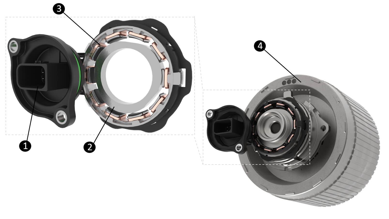 |
|---|
| 1. Resolver Connector 2. Resolver Rotor 3. Resolver Stator 4. Drive Unit Rotor |
| Drive Unit Resolver |
Cooling and Lubricationlink
Motor Gearbox Lubrication and Coolinglink
Effective thermal management is crucial for ensuring the optimal performance and reliability of electric drive units, particularly those with permanent magnet motors. These motors utilize rare-earth magnets that are susceptible to demagnetization when exposed to high operating temperatures.
The motor gearbox oiling system integrates both thermal control and lubrication functions. A network of oil passages circulates gearbox fluid (oil) through both the motor and the gearbox. This dual-purpose system cools the stator and rotor assemblies while simultaneously lubricating moving components like bearings and gears. The heated oil is then pumped through the heat exchanger, where thermal energy is transferred to the vehicle coolant system.
Specificationlink
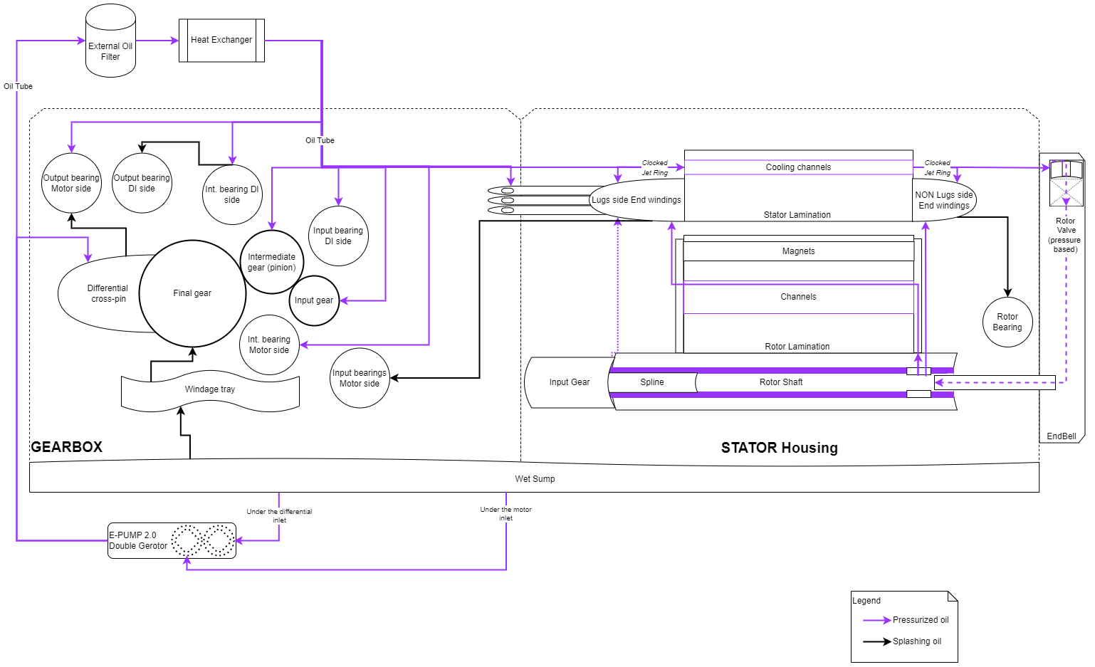 |
|---|
| C1PM Oiling Schematic |
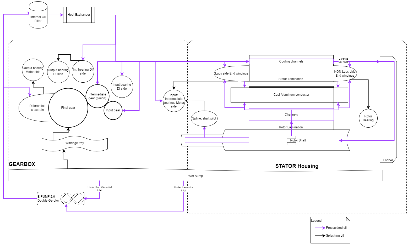 |
|---|
| C1IM Oiling Schematic |
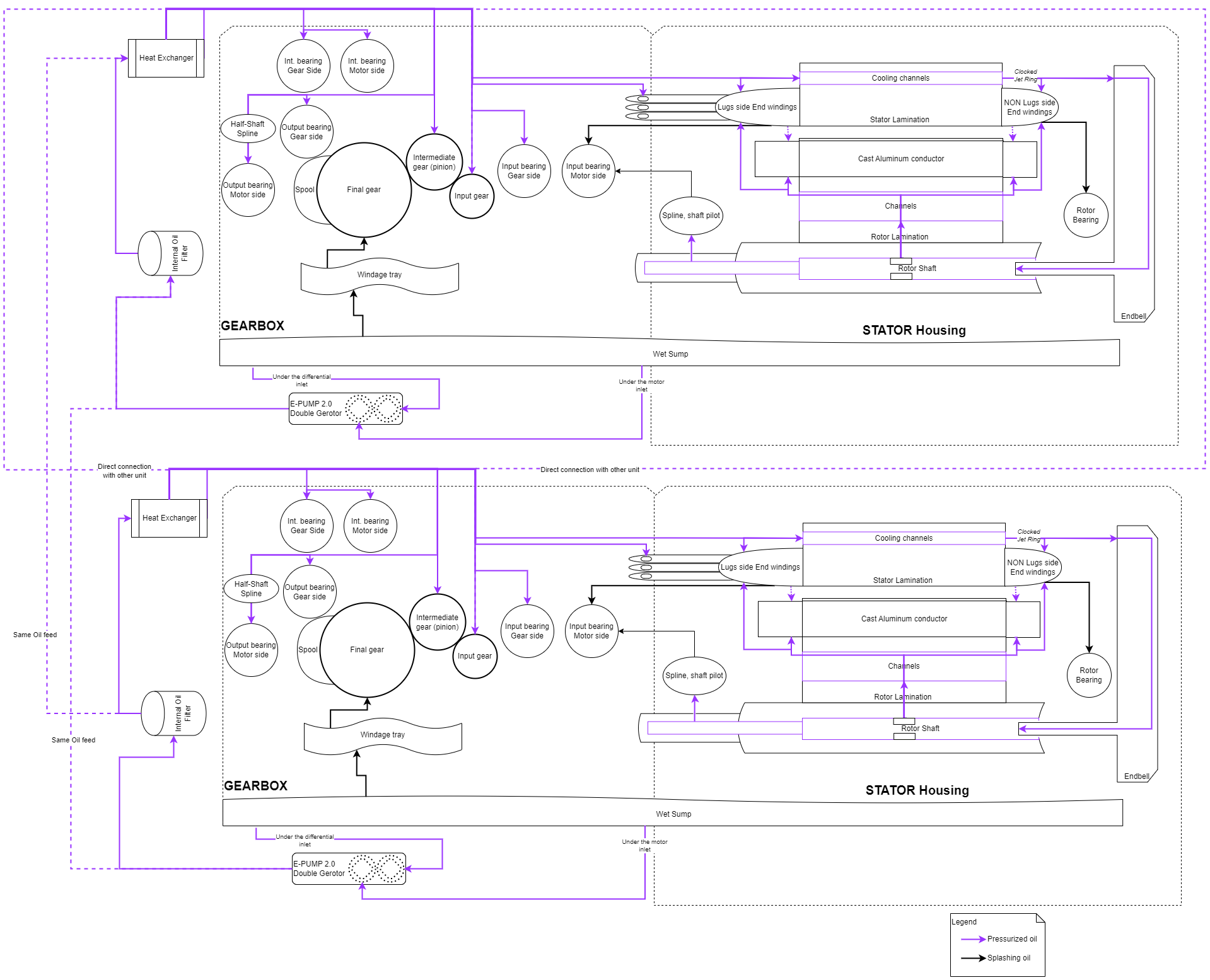 |
|---|
| C2IM Oiling Schematic |
Oil Pumplink
Specificationlink
Operationlink
The primary function of the oil pump is for cooling the internal components of the motor gearbox, but a small flow of the circuit is used to actively lubricate some rotating components including gears and bearings. An electrically powered oil pump allows flexibility of controlling flow rate independent of the motor speed. The flow control is optimized to deliver the best thermal performance and efficiency based on operating conditions. Ability to circulate oil while the vehicle is stationary enables the stationary waste heat feature.
During normal operating conditions, the oil pump is controlled by the drive inverter based on the system thermal requirements. The pump controller is connected to the inverter using a wire harness and communicates via LIN protocol. During operation, the oil pump continuously transmits parameters such as speed, phase current, and oil temperature to drive inverter which uses these inputs to define the pump duty cycle. The oil pump has built-in protection that can override external commands and set its own duty cycle based on operating conditions.
Cybertruck is equipped with second generation of the electric pump, called pump 2.0, which operates on 48V power input. The pump has two inlets and one common outlet. The PCBA is submerged in oil which creates several improvements:
- PCBA temperature sensor, which is also used for oil temperature estimation, is located on the lowest point of the PCBA where it is always submerged in oil, which improves oil temperature estimates
- Increases thermal limits of the pump through better heat dissipation in oil.
- Reduce cost and complexity by eliminating thermal gap pad, and cooling fins on the cover
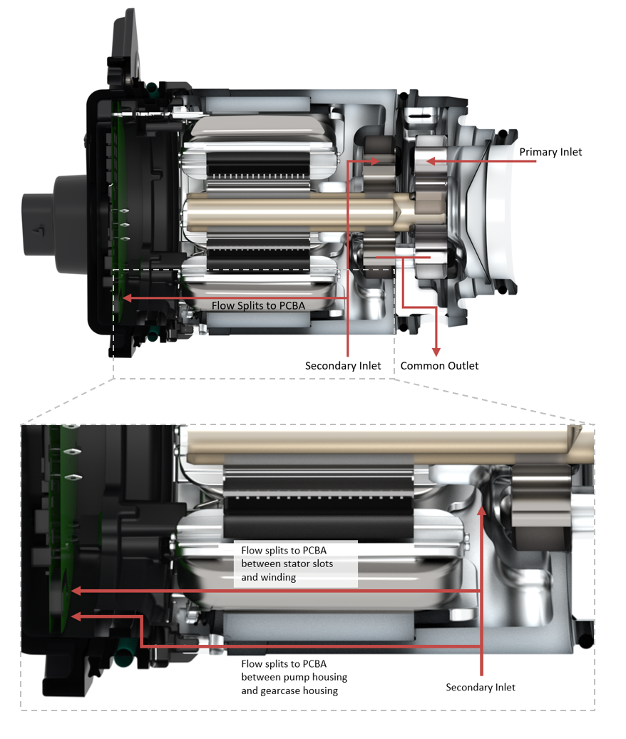 |
|---|
| 48V Oil Pump 2.0 Cutaway |
Serviceabilitylink
Alerts
- DIx_a149_oilPumpFailure - Is triggered when there is loss of power or communication to the pump, or the pump is reporting persistent faults. Vehicle will enter limp while this alert is present.
- DIx_a149_fluidTempSNA - Oil pump fluid temperature signal is not available. Can be caused by thermistor failure or communication issue.
- DIx_a152_linError - Indicates Local Interconntect Network (LIN) communication error with the oil pump. Check wiring between the drive inverter and the oil pump.
- DIx_a149_insufficientFlow - Insufficient flow triggers when pump cannot maintain minimum amount of flow at warm temperatures. In cold temperatures, there is logic to have greater tolerances due to higher inaccuracies.
- DIX_a149_motorOpenPhase - Open phase condition internal to the pump. Expect the pump to not start or abruptly stop. Could see pump state enable but not starting. Try to drive the motor with external power source to confirm failure.
- DIX_a149_motorShorted - Short condition internal to the pump. Expect pump to not start or drop out. Current draw might be high.
Oil Pressure Detectionlink
Operationlink
During operation, the drive inverter is constantly monitoring the estimated oil pressure in order to detect any abnormalities to protect hardware from failure. This can be caused by various conditions such as oil leaks or blockages in the oiling circuit. The pressure is estimated based on load on the pump (using phase current), pump speed, and oil temperature. A lookup table is used to compare the estimated pressure to the expected pressure at given operating conditions.
Serviceabilitylink
Alerts
- DIX_a251_oilPumpService - Is set when these pressures deviate more than expected. Alert payload DIX_a251_reason will indicate the cause of the alert. Low pressure is likely due to low oil level or blockage at inlet, causing the pump to pull air. High pressure can indicate a blockage in the system.
Signals
- DIX_oilPumpFlowActual - Actual flow estimated based on pump rotor RPM and oil temperature. In cold temperatures, flow actual should not get very high. If high flow is seen at low temperatures, the pump is likely taking in air.
- DIX_oilPumpFlowTarget - Target flow for given operating condition. Relationship between flow actual and target is temperature dependent. High temperatures should track close. At low temperatures, it is expected to deviate.
- DIX_oilPumpFluidT - Oil temperature as measured by the temperature sensor on the oil submerged PCBA. During low temperature and low flow rate operating conditions, the sensor may not be receiving sufficient oil flow accurate drive unit oil temperature measurements. Under those conditions, a thermal model is used for more accurate temperature estimates.
- DIX_oilPumpPressureResidual - Anything but 0 is not expected. -ve value indicates pressure too low; positive indicates pressure is too high. Can see this briefly during transients, looking back to see if condition is persistent is good for confirmation. The higher the oil flow, the more confidence there is in this signal.
Routines
- TEST-SELF_DIX_X_OIL-PUMP-PRESSURE - Following gearbox fluid refill, it is important to run the oil pressure check routine in order to confirm the pressure has returned to normal and to reset the service alert. Failure to run the routine will not clear the alert until a long drive is completed as part of the periodic pressure checks that occur while driving.
Drive Inverter Coolinglink
Power semiconductors are the critical components within a drive inverter, and they are highly sensitive to changes in temperature. When the power electronics get too hot, they can fail quickly, resulting in permanent damage to the inverter. Therefore, it is crucial to maintain optimal cooling conditions to ensure the longevity and performance of the drive inverter.
Cooling of the power semiconductors is done via the inverter heatsink, which transfers heat from power semiconductors into the vehicle coolant loop. Low flow detection systems have been developed to catch cooling issues early on and prevent permanent damage to the inverter.
Low Flow Detectionlink
Low flow detection works by monitoring coolant temperature change between the inverter inlet and outlet. When the outlet temperature diverges from the estimated temperature, an alert is triggered, indicating that there may be a cooling issue. However, low flow detection alerts can be triggered for various reasons, making them difficult to troubleshoot.
Specificationlink
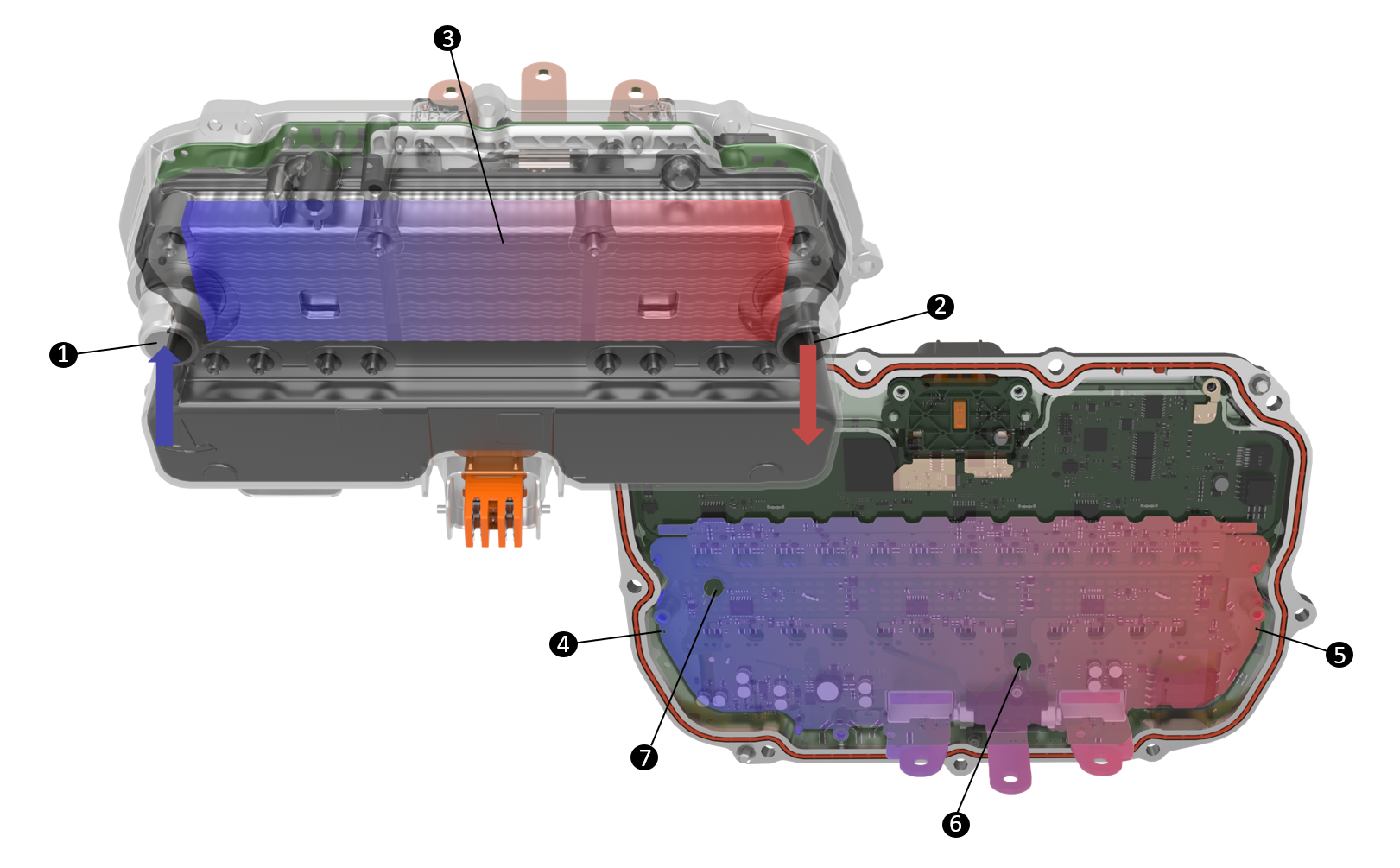 |
|---|
| 1. Coolant Inlet |
| 2. Coolant Outlet |
| 3. Inverter Heatsink |
| 4. Inlet Temperature Sensor located on PCBA (DIx_fluidInTemp) |
| 5. Outlet Temperature Sensor located on PCBA (DIx_inverterT) |
| 6. Infrared TPAK Temperature Sensor (DIx_TPak1Temp) |
| 7. Infrared TPAK Temperature Sensor (DIx_TPak2Temp) |
| Coolant Flow and Temperature Sensors |
Operationlink
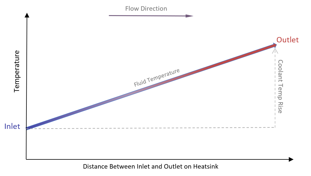
When coolant flows across the inverter heatsink, there is a temperature rise from inlet to outlet, as heat is transferred from inverter to the coolant. Based on the operating conditions of the inverter, it is possible to estimate the losses in the form of heat and the expected coolant temperature to rise. When the actual coolant temperature rise deviates from estimated, this indicates a low or no flow condition. The following inputs are used to estimate the outlet temperature:
- EGGRIGHT3_ coolantPTInlet
- EGGRIGHT3_coolantFlowDIXActual
- DIx_motorCurrent
 |
|---|
| Coolant Temperature Increase Across Inverter |
Serviceabilitylink
Alerts
DIX_a103_lowFLow will set anytime the algorithm detects a low flow condition. The following payloads may be helpful in troubleshooting:
- DIX_a103_fluidTorDeltaT: 4DI inverter fluid temperature difference i.e., (DI*_inverter-DI*_fluidInTemp).
- DIX_a103_inverterTemp: 4DI max TPAK temperature i.e., max [TPak1Temp, TPak2Temp].
- DIX_a103_ambientTemp: Ambient temperature from EGGRIGHT3.
- DIX_a103_sensorTempEst: 4DI outlet sensor estimate (what thermal model is estimating DIX_inverterT to be).
Signals
- DIX_fluidInTemp: Inlet coolant temperature sensor on the drive inverter.
- DIX_inverterT: Outlet coolant temperature sensor on the drive inverter.
- DIX_ TPak1Temp, DIX_ TPak2Temp: IR sensors above TPAKs on phase B & C.
- EGGRIGHT3_tempCoolantPTInlet: this is the immersed coolant sensor upstream of the drive inverters (and PCS).
- DIX_coolantFlowReq: this is the amount of flow in LPM the inverter is requesting.
- EGGRIGHT3_coolantFlowPTActual: The coolant flow in LPM of the powertrain loop.
- DIX_motorCurrent: filtered motor current.
- EGGRIGHT3_pumpPowertrainRPMActual: the measured RPM of the PT pump.
Troubleshooting Tips
Possible hardware conditions causing the low flow algorithm to trip:
- Low coolant level.
- Restriction/blockage in the coolant loop.
- Failed powertrain loop (PT) pumps.
- Miscalibrated coolant valves.
- Swapped powertrain (PT) and HV battery (BAT) coolant sensors.
- Swapped coolant pumps.
Known behaviors that may challenge the low flow algorithm and should be checked at the time of low flow detection:
- Waste Heat Mode.
- Highly transient coolant temperature.
- After thermal mode switches (between parallel & series), generally after super-charging.
- Rapid environmental changes, such as driving through a long tunnel.
Case review
- Is DIX_fluidInTemp within a few degC of EGGRIGHT3_tempCoolantPTInlet? These temperature signals should always be close together when there is adequate flow.
- Is DIX_inverterT within a few degC of DIX_fluidInTemp?
- These signals can deviate during waste heat mode. Check DIX_wasteState.
- Is the drive inverter getting the flow it’s requesting? Check DIX_coolantFlowReq vs. EGGRIGHT3_coolantFlowDIXActual
- Does the coolant pump actual rpm match the target? Check EGGRIGHT3_pumpPowertrainRPMTarget match EGGRIGHT3_pumpPowertrainRPMActual?
- Is the pump actually running? Is it audible?
Differential Lockerlink
Specificationlink
 |
|---|
| Differential Locker Components |
Operationlink
A differential locker, also known as a locking differential or diff locker, is a device used to enhance traction and improve off-road performance. It is housed inside the differential, which is a component that distributes power between the wheels (on the same axle) while allowing them to rotate at different speeds, such as during turns.
In an open differential, power follows the path of least resistance, going to the wheel with the least traction. This can lead to situations where a wheel on a slippery surface spins while the other wheel with better traction remains stationary.
A differential locker addresses this by "locking" the differential, ensuring that both wheels on the same axle rotate at equal speeds, regardless of traction differences. This is particularly advantageous in off-road and low-friction conditions, as it enables both wheels to receive power, providing better stability and traction.
Cybertruck is equipped with an electric diff locker on all single motor drive units (C1IM and C1PM). In a dual motor drive unit (C2IM), a differential locker is not needed, as both wheels can be controlled independently.
 |
|---|
| Differential Locker Locking/Unlocking |
| Locking | Unlocking |
|---|---|
|
|
The request flow to the locker coil is as follows:
An engage/disengage request originates from the UI via user press and travels through each node to command coil actuation. Each node is responsible for monitoring and protection.
- UI
- Provide and interface between the user and the DFLKx.
- DI (system)
- System level availability and unit level availability, to tell UI whether front or rear lockers are available (unavailable units are disabled on the screen).
- Enforcement of top speed for locker engagement and operation.
- Delay of actuation while TC/VDC/ABS are active.
- Coordinate engagement/disengagement of front/rear differential locker.
- DIx (unit)
- Unit level availability to ensure all inputs are active and not faulted.
- Wheel speed difference protection.
- Time outs if no engagement is reported from DFLKx.
- DFLKx
- Engagement/disengagement of the differential locker
- Differential locker position sensing and reporting
- Hardware protection (voltage, current, thermal)
If any of the conditions are not met, each node can block the request from going though. Some examples include:
- If vehicle speed is too high for actuation, DI will stop request at that level (UI button will not be available)
- If wheel speed difference is too high, DIx unit will stop the request at that level to prevent damage to the locker
- If PCBA is too hot, DFLKx unit will stop the request at that level
Position sensinglink
The differential locker uses an Inductance-to-Digital Converter (LDC) to sense the position of the "moving plate". It operates by applying an AC excitation signal to a sensing coil, generating a changing magnetic field around it. When the metallic "moving plate" changes proximity to the sensing coil, it induces eddy currents in the "moving plate". These currents affect the sensing coil's inductance, which is detected by the LDC's capacitive sensor. The resulting digital output represents the position of the moving plate relative to the sensor coil, enabling accurate non-contact position sensing of the differential locker.
Serviceabilitylink
 |
|---|
| Differential Locker Signal Communication Diagram |
Noise Vibration Harshness (NVH)link
All electric motors produce some level of noise and vibration due to the mechanical movement and interaction of various components such as gears, bearings, and shafts, which create vibrations that propagate as sound waves. Additionally, the electromagnetic forces and switching operations within the drive unit can contribute to the generation of audible noise. While some levels of NVH are considered within design parameters, other loud or abnormal noises can be an early indicator of a wear or potential failure within the drive unit.
- Electric Motor: The electric motor converts electrical energy into mechanical motion to propel the vehicle. It can generate noise and vibrations due to electromagnetic forces, mechanical imbalances, or bearing issues.
- Power Electronics: Power electronics internal to the drive inverter can introduce high-frequency electrical noise and may produce audible noise due to switching operations.
- Gearbox: Gearbox is used to adjust the torque and speed delivered to the wheels. Gears can generate noise and vibration due to meshing forces, misalignment, or inadequate lubrication.
- Mounts and Mounting Structures: The motor mounts are design to dampen vibrations and isolate the drive unit for the vehicle structure. Worn or misaligned bushings can ground out and transmit vibrations directly to the vehicle structure.
All Cybertruck drive units are wrapped in a multi-piece sound deadening cover to absorb, block, or dampen sources of NVH from the drive unit, contributing to a quieter and more comfortable driving experience. Different sections of the NVH cover are joined by convenient ball socket snap in clips for easy of access for maintenance.
Serviceabilitylink
Prior to replacing any components, always check for NVH leak paths and ground outs (are components physically touching?):
- Physical ground outs:
- Is the drive unit oriented correctly? Are mounts centered and secured in nominal position?
- Are the motor mounts in good shape? Are they cracked or torn? Are there any mounts preloaded?
- Is there any tension or stiffness in the ground strap?
- Are there any other components surrounding the drive unit that could be contacting under hard acceleration?
- Leak paths:
- Inspect all seal and grommets on the body to ensure they are properly seated.
- Use a Smoke Machine or an Ultrasonic Leak Detector to check for any leak paths.
- Other:
- Drain and inspect the gearbox fluid. Is the drained fluid volume expected per specification? Is there debris in the oil?
- Check for historic oil pump pressure alerts:
- DIx_a251_oilPumpService with payload DIx_a251_reason = "DI_OILPUMP_SERVICE_INSUFFICIENT_FLOW" or DIx_a251_reason = "DI_OILPUMP_SERVICE_PRESSURE_LOW"
- Inspect the halfshafts.