Electric Power Steeringlink
Last updated: October 20, 2023
Overviewlink
 |
|---|
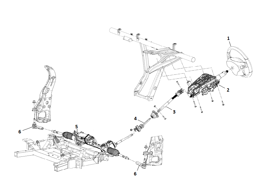
| 1. Steering wheel 2. Steering column assembly 3. Upper i-Shaft 4. Lower i-Shaft 5. Steering Gear 6. Tie Rod |
| Component Locations |
The Electric Power Assisted Steering (EPAS) system comprises a steering wheel, a collapsible steering column assembly that is bolted to the vehicle dashboard cross-beam and an electrically operated rack and pinion steering gear. The tie-rods are at each end of the rack and transmit the movement of the rack to the front road wheels.
Even in the event of a malfunction of the vehicle electrical system or the electric assistance, the vehicle can still be steered thanks to the mechanical connection between the steering wheel and the road wheels
Warning
Greater effort than normal is required to turn the steering wheel.
EPAS also has 3 different, Driver selectable, modes: Comfort, Sport, and Standard.
Adjustments can be made by the Driver to the feel/sensitivity using the Touch Screen – Controls > Driving > Steering Mode
| Mode | Description |
|---|---|
| Comfort | More assistance - reduces effort to turn the Steering Wheel making it lighter to the touch |
| Standard | Best feel in all conditions |
| Sport | Least assistance - Increases effort to turn the Steering Wheel giving it a “Sporty” more feedback feel |
| Manufacturer | Abbreviation | Vehicle production date | |
|---|---|---|---|
| Bosch | EPAS | SOP - Nov 2016 | |
| Mando | EPAS2 | Feb 2016 - Apr 2019 | |
Operation of Electric Power Assistancelink
 |
|---|
Steering Assistance L538link
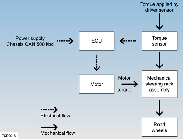
The ECU takes readings from the Torque Angle Sensor, mounted in the Input Shaft Housing, of the Drivers requested input torque as its primary input and runs control algorithms to translate into the appropriate Motor current.
The ECU also takes in other CAN inputs in order to vary this assistance level.
Information from the user interface (UI) informs the ECU the level of assist the driver has requested.
Speed information from ESP reported vehicle speed (and Drive Inverter motor RPM for vehicle speed correlation) alters the level of assistance, with more being provided at low speeds.
EPAS synchronizes its internal steering angle sensor to the external SCCM steering angle sensor in order to learn absolute steering wheel angle.
SCCM, ESP and RCM combined to get an angle of direction of the vehicle and minor adjustments are made to compensate for offsets in the alignment
If equipped the DAS module can directly request steering outputs for autopilot features.
Note
Remember that EPAS behavior relies on data from many different systems via CAN.
Steering Assistance VGR66 & VGR66Gen3link
Additional to L538 both types of VGR generation systems work the same except that the Gen3 has built in redundance in the form of additional ECU, Inverter and wiring.
The ECU1 (primary) controls the Motor.
On detecting an error ECU2 (secondary) takes over.
Both ECUs have their own torque sensor and circuit board to drive the Motor, also separate connections to the BUS/12V Harness of the vehicle so that if any connection is lost, the system will still continue to operate.
ECU1 is connected to the Party Bus (Secondary CAN)
ECU2 is connected to the Chassis Bus (Primary CAN)
An internal bus between ECU1 and ECU2 transmits the messages the other is not receiving on the Private CAN
The most critical systems communicate with the EPAS over two buses in order to provide redundancy in case of various faults.
Component Descriptionslink
Steering Column Assemblylink
 |
|---|
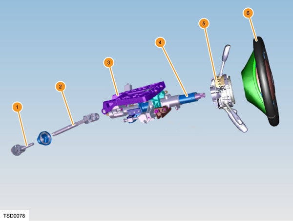
| 1. Intermediate link - lower 2. Intermediate link - upper 3. Sliding carrier 4. Steering column 5. Steering column control module (SCCM) 6. Steering wheel |
| Steering Column Assembly |
The steering column assembly comprises an aluminum base plate, a sliding carrier, pivot brackets, and a collapsible shaft assembly. The sliding carrier is connected to the base plate using an M-shaped wire, which is permanently deformed by the sliding carrier when the column is subjected to a severe impact. The upper column mounting bolts pass through the column base plate and are secured into weld nuts in the vehicle cross beam.
The three-spoke steering wheel is manufactured from molded rubber, with a leather trimmed rim. It is secured to the steering column using 66 non-indexed splines and a flathead internal hexagon bolt.
The Steering Column Control Module (SCCM) has integrated Driver input switches for turn signals, steering column position, gear selector, wiper/washer controls and dependant on configuration either standard Cruise Control or Driver Assist Control are housed in an assembly that is a press fit onto the steering column assembly. Also integrated into SCCM is the Steering Angle Sensor (SAS), this communicates the Steering Column Angle to the Chassis CAN
The steering column is adjustable for reach and rake. Two electric motors turn plastic drive nuts that are attached to drive screws, which in turn are connected to the upper pivot bracket and shaft assembly.
EPAS Electronic Control Unit (ECU)link
The EPAS ECU is a sealed unit mounted on the motor. It houses the microprocessor and the output stage for the motor. The ECU is pre-programmed with vehicle data and operating parameters with which to calculate the motor drive current, based on signals sent by the torque sensor and CAN data signals from other vehicle systems.
The ECU has Diagnostic Trouble Codes (DTCs) and live data parameters can be accessed using Toolbox.
 |
|---|
Steering Gearlink
 |
|---|
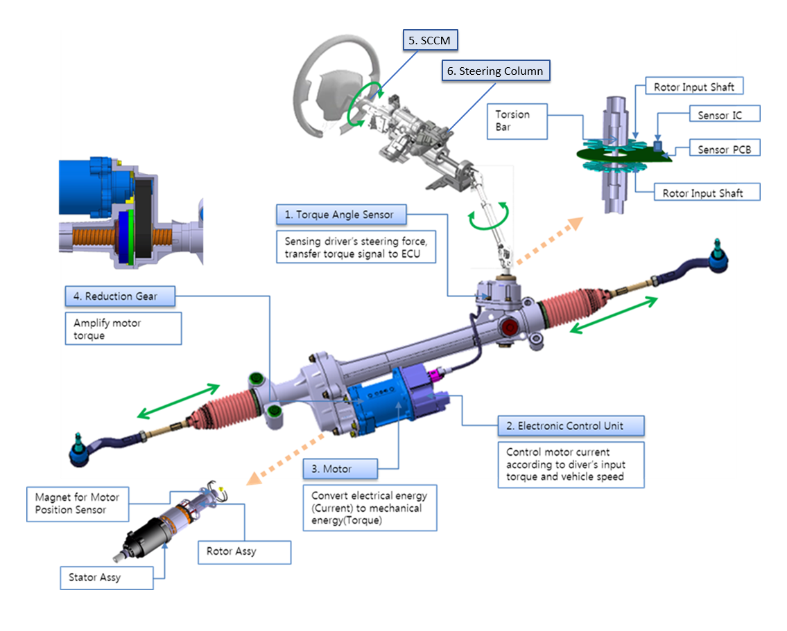
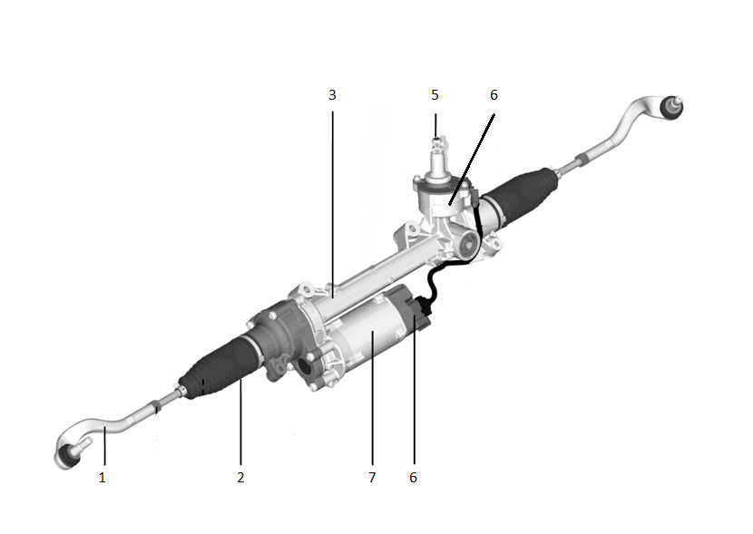
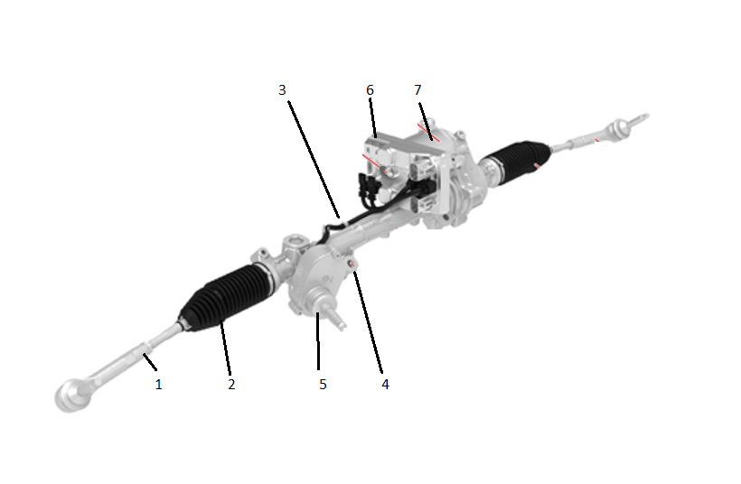
| 1. Outer Tie Rod 2. Inner Tie Rod (inside rubber bellows) 3. Steering Gear 4. Torque Sensor 5. Input Shaft 6. ECU 7. Motor |
| Steering Gear L538 |
|  |
| 1. Outer Tie Rod
|
| 1. Outer Tie Rod
2. Inner Tie Rod (inside rubber bellows)
3. Steering Gear
4. Torque Sensor
5. Input Shaft
6. ECU
7. Motor |
| Steering Gear VGR66|
 |
|---|
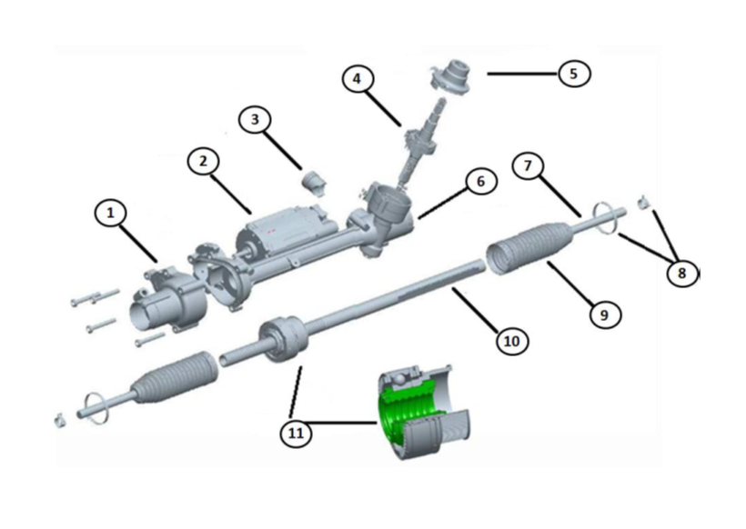
| 1. End Housing (belt drive and ball screw) 2. Motor 3. Yoke 4. Input Shaft/Pinion Assembly (including Torque Sensor) 5. Cover 6. Housing 7. Tie Rod 8. Clips 9. Rubber Bellows 10. Rack Bar 11. Ball Screw Assembly |
| Steering Gear Internal |
EPAS consists of a housing with an internal rack. The steering torque supplied by the steering wheel is transmitted to the input shaft by the steering column and the intermediate shaft. The yoke presses the rack against the steering pinion so as to keep the clearance constant and play-free. A one-time adjustment of the adjusting screw on the yoke is done at the manufacturer; this screw may not be readjusted in the field. The steering input shaft transforms the radial movement into a linear one and transmits the movement to the rack.
The torque sensor is arranged on the input shaft. Its task is to measure the steering torque and to transmit it to the electronic control unit. The servo motor generates an assistance torque. Transmission to the rack takes place in the End Housing via a belt drive.
The tie rods and the outer ball joints are arranged at the ends of the rack, they transmit the movement of the rack to the road wheels. Even in the event of a malfunction of the vehicle electrical system or the electric assistance, the vehicle can still be steered thanks to the mechanical connection between the steering wheel and the road wheels.
Motorlink
 |
|---|
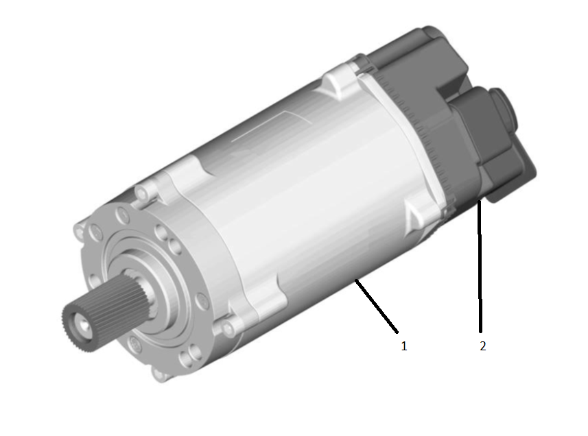
| 1. Motor Unit 2. Electronic Control Unit (ECU) |
| Motor |
The Motor Unit consists of the electronic control unit and the electric servo motor and is fitted to the steering housing parallel to the rack. The control unit, fitted to the electric servo motor is connected mechanically to the servo motor housing in a way making the two inseparable.
The control unit acquires various input signals such as steering torque, vehicle driving speed, steering angle, and steering velocity. The steering torque signal is compared with the characteristic stored in the control unit, so that the steering assistance required can be determined based on this data.
The servo motor is connected with the housing of the servo-end through drive. Dependent on the actuation by the control unit the electric servo motor generates a torque, which is transmitted by a toothed drive arranged on the motor shaft via a toothed rubber belt the servo motor transmits the power to the recirculating ball gear. The effective steering power at the rack is the sum of the power of the steering torque applied at the steering wheel and the power of the steering assistance supplied by the servo motor.
Torque Sensorlink
 |
|---|
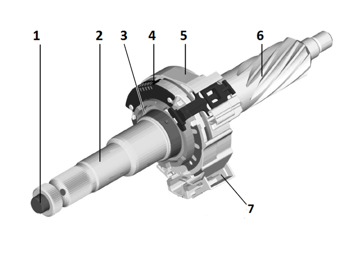
| 1. Torsion Bar 2. Steering Input Shaft 3. Magnet Ring 4. Sensor Module 5. Clock Spring 6. Steering Pinion 7. Electrical Connector |
| Torque Sensor |
The torque sensor measures the steering torque the driver exerts on the steering wheel. The control unit uses the measured value to calculate the steering assistance to be provided by the motor.
On the torque sensor the steering input shaft and the steering pinion are connected with each other by means of a torsion bar. A magnet ring is fitted to the steering input shaft. When the driver exerts a steering torque on the steering wheel, the torsion bar and, as a consequence, also the magnet ring, are rotated in relation to the sensor module.
Via the torsion of the torsion bar the contactless sensor measures the steering torque exerted. The clock spring transmits the signal coming from the torque sensor to the housing connector. The sensor cable towards the servo motor is plugged in the connector.
Ball Screw Assemblylink
 |
|---|
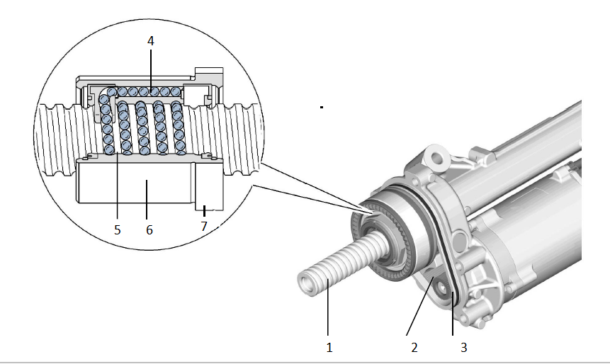
| 1. Rack 2. Toothed Belt 3. Toothed Wheel 4. Ball Return Channel 5. Ball Chain 6. Ball Recirculation Nut 7. Toothed Wheel |
| Ball Screw Assembly |
There is a mechanical connection between the servo motor and the servo-end through drive. Via a toothed belt and recirculating ball gear the radial drive movement of the servo motor is converted into a linear movement of the rack.
Via a large toothed wheel (7) the toothed belt (2) drives the recirculating ball gear. In the recirculating ball gear the ball chain (5) is led back through an internal ball return channel (4) in the ball recirculation nut (6).
The rotation of the recirculating ball gear causes the rack (1) to move to the left or to the right.
Haptic Feedbacklink
This function is used with the vehicle’s driver assistance components to alert the driver that a vehicle has un-intentionally crossed a lane marking. The feedback is provided through a high frequency vibration of the steering wheel generated by the steering gear. This does not have any effect on overall steering feel or the current driving path.
EAC External Angle Controllink
This function is used to steer the vehicle using the EPAS by an external angle request and is the interface between the Steering Gear and the EPAS ECU module to support:
- Autosteer - Driver Assist System Functions
- Autopark
- Summon
Motor Torque is commanded to control EPAS Steering Angle to match DAS requested Steering Angle when autopilot is engaged.
EAC is inhibited if any of the following are TRUE
- High vehicle road speed
- Hands on steering wheel detected
- Motor assistance detected level too low
- Steering angle suspected inaccurate
- Differences between desired and actual steering rack angle position
- Defined inputs from CAN (DAS, ESP, GTW, EPB, SCCM)
The system will indicate a fault if any of the following are TRUE
- CAN error resulting in BUSOFF condition
- MIA conditions on CAN
- Invalid CAN data
- LOAD_SHED detected on GTW
This fault state is a latching state and requires a power cycle to clear.
Hands-On Detectionlink
EPAS monitors torsion bar torque to determine the level of driver interaction with the steering. The level of hands-on detection is set by evaluating the amount of torsion bar torque exceeding a calibrated threshold for a calibrated period time.
There are 4 levels of detection
| Level | Description |
|---|---|
| Level 0 | No driver interaction and no effect on EAC |
| Level 1 | Light driver interaction and no effect on EAC |
| Level 2 | Moderate driver interaction |
| Level 3 | High driver interaction, cancels Autopilot and disables EAC |
Power Faultslink
If the vehicle power supply is interrupted, either a full vehicle or EPAS power, the driver can continue to steer the vehicle due to the mechanical connection between the steering wheel and the road wheels.
Warning
Greater effort than normal is required to turn the steering wheel.