Suspension
Suspensionlink
Overviewlink
The suspension is the mechanical linkage that connects the wheels and tires to the front and rear subframes. The subframes are attached to the body.
A vehicle’s suspension controls tire motion, absorbs energy from the road, and reduces vibration from road imperfections. The 2024+ Model 3 uses multi-link suspension in the rear and a variation of the double wishbone design on the front. Although complex, these suspension geometries allow great design freedom to tune the suspension to optimally split the difference between immediate response and ultimate cornering grip, and comfort. The system is comprised of both steel and aluminum with each piece being analyzed and optimized for its task. Due to manufacturing variability and wear over time, the alignment of the wheels with respect to each other may require adjustment. The most important alignment parameter, toe, has built in adjustment mechanisms. Additional alignment values might be changed with longer procedures or worn component swaps.
Component Specificationslink
Front Suspensionlink
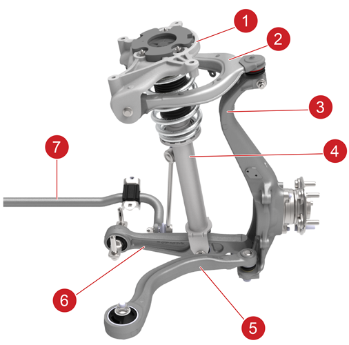
The front suspension is a variation of the double wishbone design. This geometry is widely used in higher end cars and racing because it allows for independent tuning of multiple parameters of the suspension. The double wishbone design usually consists of a short upper control arm and a longer lower control arm, however in the case of the Model 3 the lower link is actually comprised of 2 links. This variation moves the steering axis of rotation of the front tires in such a way as to make the vehicle more stable and planted. The 2 lower arms are aluminum forgings that connect to an aluminum knuckle that houses the wheel hub. The knuckle is tall in order to transfer most of the lateral loads from the tire through the two lower links, while the upper arm experiences less load. The shock absorber and the upper control arm connect to a structural reinforcement called the Front Upper Control Arm (FUCA) mount that is bolted into the body.
 |
|---|
| 1. Front Upper Control Arm (FUCA) mount 2. Upper control arm 3. Knuckle 4. Shock absorber 5. Lower compliance link 6. Lower lateral link 7. Stabilizer bar |
| Front Suspension, Overview |
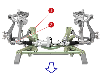
The front damper and spring come together as one assembly and connect to the lower lateral link. A spring steel stabilizer bar exists in order to tune the roll stiffness of the front suspension. The upper arm and the lower lateral link are mostly responsible for the camber and camber curve of the wheel. The lower compliance link is mainly responsible for the caster, which can be adjusted by moving the FUCA mount. The steering rack connection to the knuckle is through a tie rod that is adjustable in length, allowing for adjustment of the front toe. The lower links and the steering gear are all connected to a structural member called a subframe that is made of stamped and welded steel and provides a mounting structure between the body and the suspensions.
 |
|---|
| 1. Subframe 2. Tie rod |
Note
The arrow points to the front of the vehicle.
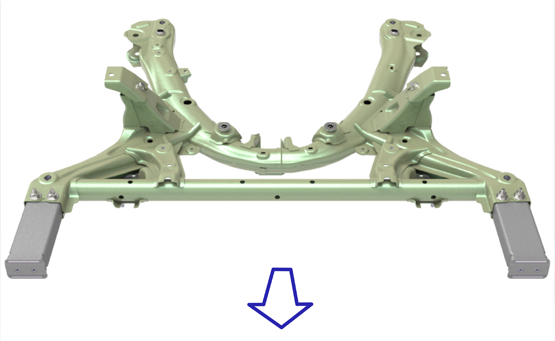
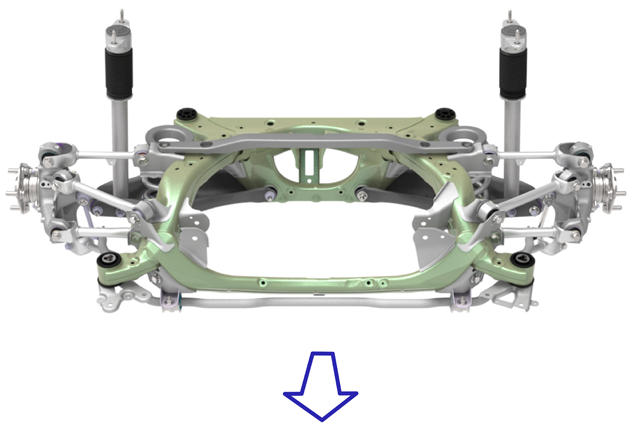
The use of a subframe provides extra rigidity in the body for mounting suspension links, and is an important part of crash management. The subframe also simplifies the manufacturing process, allowing the entire front end to be built as a unit and mounted to the body. It also provides mounting points for things such as a steering rack and the front fascia.
 |
|---|
| Front Subframe |
Note
The arrow points to the front of the vehicle.
Rear Suspensionlink
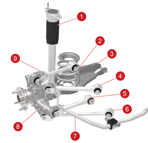
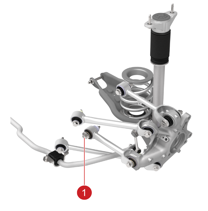
The rear suspension is a multi-link set up comprised of 5 arms. The arms are all steel and either tubes or stamped. They connect to an aluminum knuckle which houses the wheel hub. The high strength steel arms are effective at transmitting loads while the aluminum knuckle reduces unsprung weight. The spring and damper are split but both connect to the lower aft link. The spring is a larger diameter but lower profile while the strut is thinner but longer; by splitting them up they can be packaged to allow for much more interior space in the trunk for storage.
 |
|---|
| 1. Damper 2. Spring 3. Lower compliance link 4. Upper fore link 5. Toe link 6. Lower lateral link 7. Stabar 8. Knuckle 9. Upper aft link |
| Rear Suspension, Overview |
The upper and lower aft links are mainly responsible for the camber and camber curve of the wheel. The fore links are responsible for the longitudinal and rotational movement of the wheel. The toe link is responsible for pointing the wheel and is the only adjustable link. There is a cam bolt on the inboard side of the toe link to allow for alignment.
The rear subframe is a stamped and welded steel structure. It provides the hard mounting points for the suspension and the rear drive unit. The subframe connects to the body in white via 4 large, main bushings. This arrangement allows the subframe to both distribute the loads from the suspension into the main structures within the unibody as well as to isolate the cabin from road inputs and drive unit vibration.
 |
|---|
| View of the Rear Suspension |
Note
The arrow points to the front of the vehicle.
 |
|---|
| 1. Cam bolt |
| Rear Suspension Toe Adjustment |
Adaptive Dampinglink
The adaptive damping's controller in right vehicle controller (VCRIGHT) allows the vehicle to be adapted to different damping characteristics according to different driving conditions for higher performance.
 |
|---|
|
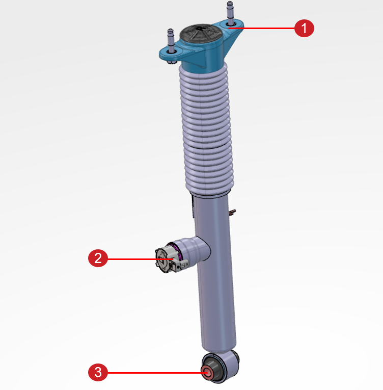
| Adaptive Damping Assembly |
Warning
- Oil and gas under high pressure in this assembly. Do not try to open it.
- Do not apply heat or flame on this assembly. Injury may occur.
4 switchable damper valves and 4 wheel accelerometers are added to this system, with 1 damper valve and 1 wheel accelerometer at each corner. Accelerometer and wheel speed sensor are integrated as one unit and installed on the knuckle of each wheel. The wheel speed sensor measures the wheel speed and sends the speed data to ESP, while the accelerometer measures the 3-axis acceleration and sends the acceleration data to VCRIGHT through the Automotive Audio Bus (A2B) interface. The data is then processed by VCRIGHT and the appropriate damper valve is actuated to change the damping characteristic of the vehicle.
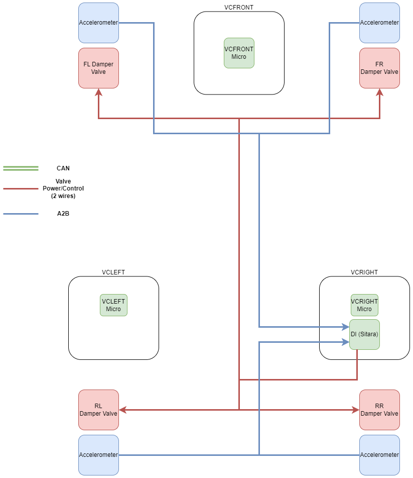
Damper valves are proportional valves, unlike on-off solenoids. As the vehicle moves, these valves are continuously adjusted with high frequency to regulate the amount of oil flowing through the valve. The damper valves are managed by the external drive inverter micro within VCRIGHT, since the necessary accelerometer data used to modulate the damping characteristics is also processed on VCRIGHT. This configuration allows the dampers to react quickly and smoothly to changing road conditions.
The following diagram shows the architecture of the adaptive damping system:
 |
|---|
| Adaptive Damping System Architecture |
The accelerometer on each wheel is able to provide acceleration signals for 3 axis and all accelerometers communicates with VCRIGHT over the Automotive Audio Bus (A2B). The following diagrams show the communication and data flow of adaptive damping system's A2B layout:
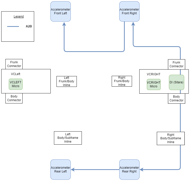 |
|---|
| A2B Communication of Accelerometers |
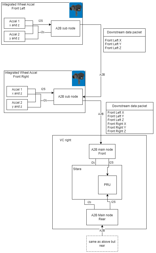 |
|---|
| A2B Data Flow of Accelerometers |
Serviceabilitylink
The suspension is serviceable by individual component replacement. If issues arise with any of the suspension links or their integrated bushings, the whole link must be replaced. The same is true with the subframes and the clevis mounting points. After suspension components are loosened, it is important to align the suspension to ensure the vehicle stability and correct tire wear.