Structural High Voltage Batterylink
Last updated: December 11, 2024
Overviewlink
The high voltage (HV) battery is the primary energy storage device in the vehicle. Its main purpose is to provide power to the powertrain for all vehicle operations.
The HV battery hosts several key components of the powertrain that are vital for vehicle functions like driving, charging, and providing power to the vehicle low or medium voltage (referred to as LV or MV) systems.
Warning
The HV battery has a lot of energy stored in a small volume. Use extreme care when handling HV batteries.
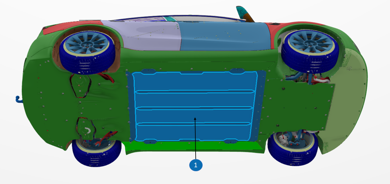
Location of the High Voltage Batterylink
The HV battery is mounted to the chassis bottom for easy removal and installation, improving vehicle dynamics with a lower center of gravity.
The structural HV battery is designed to be part of the vehicle body and provides structural properties to the chassis and body of the vehicle. The structural HV battery enclosure is integrated with the Body-in-White and provides frontal and side impact backup structure along with interior seat mounts.
The HV battery not only provides rigidity to the chassis for vehicle dynamics and vehicle impact response, but it also acts as the floor of the vehicle. The seats, carpet, center console, harnesses, thermal duct and other interior trim are mounted directly onto the structural HV battery.
 |
 |
|---|---|
| HV Battery Location | structural HV battery Removed |
 |
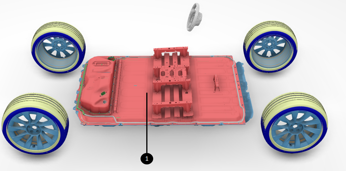 |
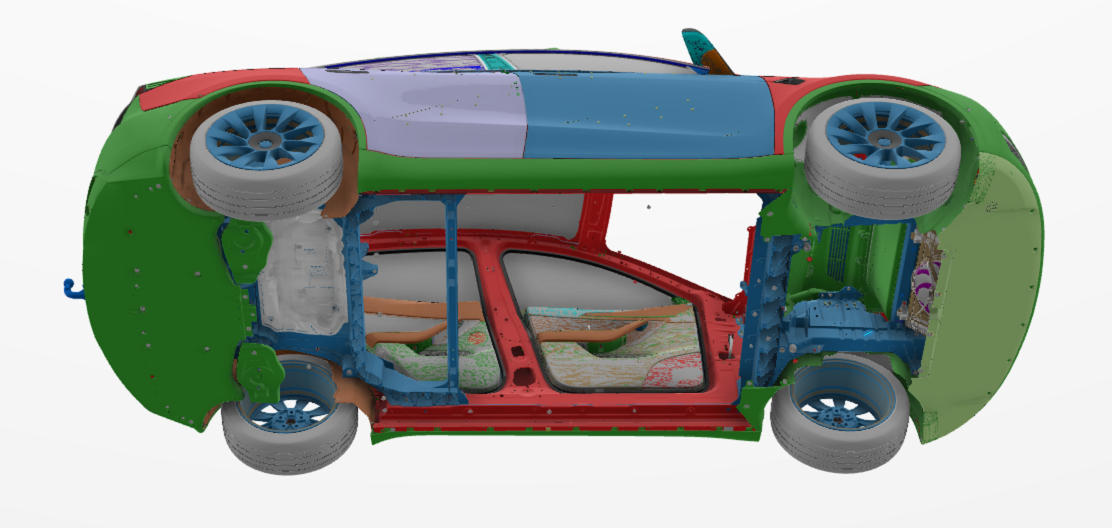
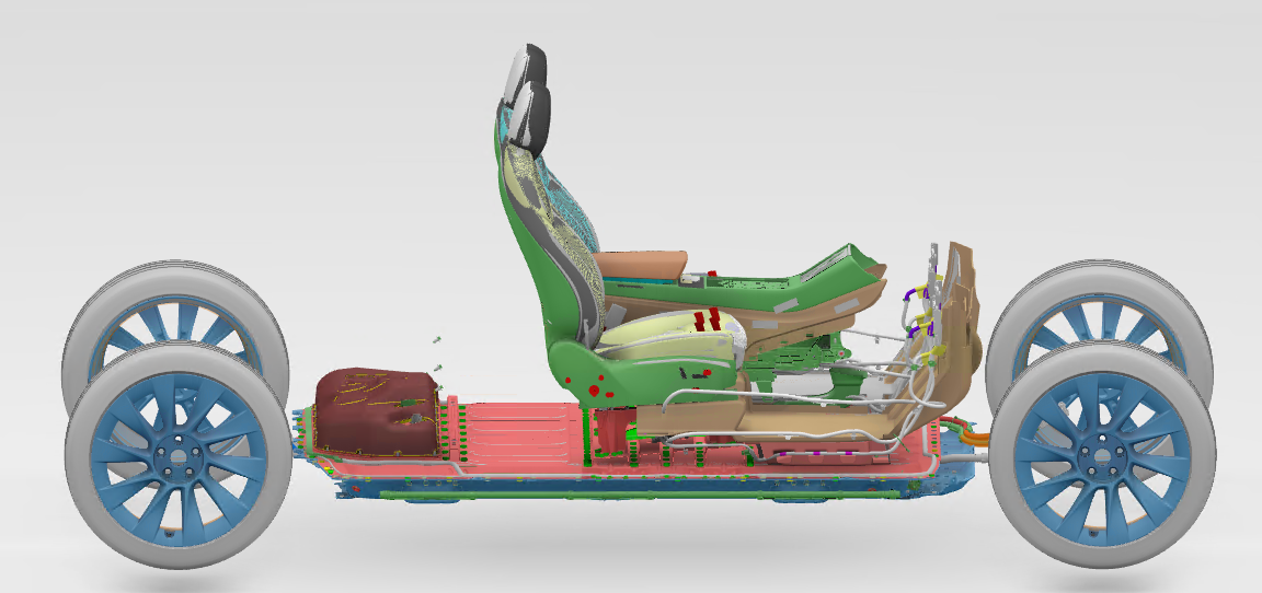
| structural HV battery with Interior Attached | structural HV battery Without Interior Attached |
The battery pack is integral to the chassis, so removing it without first removing interior components can cause them to be pulled out with the battery.
When all the attached components are removed from structural HV battery, the HV battery looks similar to a non-structural HV battery from the outside (except for the mounts of the seat rails).
Pack Generationslink
Below are the different generations of Tesla HV batteries:
| HV battery Generation | Applicable Models |
|---|---|
| Gen 1 | 2012-2020 Model S 2015-2020 Model X |
| Gen 2 | Model 3 Model Y (Non-Structural and structural HV batteries) |
| Gen 3 | 2021+ Model S 2021+ Model X |
| Gen 4 | Cybertruck |
Starting in early 2022, the structural HV battery made in Gigafactory Austin using 4680 cells was introduced on the Model Y AWD. In May 2023, the structural HV battery made in Gigafactory Berlin using Blade shape cells was introduced on the Model Y RWD. Both versions are Standard Range (SR) configurations. The structural battery Model Y AWD (4689 cells) is for the North American market and the RWD (Blade shape cells) for Europe, Middle East, and Africa (EMEA) markets.
Pack Architecturelink
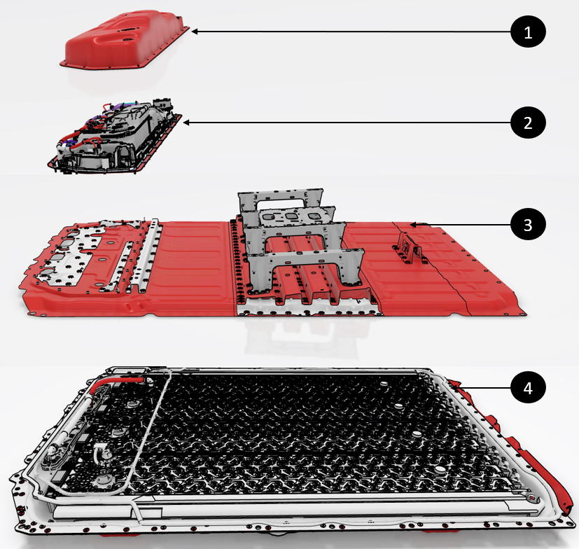
The HV battery consists of the two distinct sections:
- The module platter
- The Ancillary Bay
- The rear access service panel
- The pyro-disconnect area
The HV battery module platter includes battery cells and thermal management components, and the Ancillary Bay holds electronic components known as "high voltage devices." For more details, see HV Devices Theory of Operation.
 |
|---|
| 1. Ancillary Bay Cover 2. Ancillary Bay 3. HV battery Cover 4. HV battery Platter |
| HV Battery Architecture Sections |
Battery Platterlink
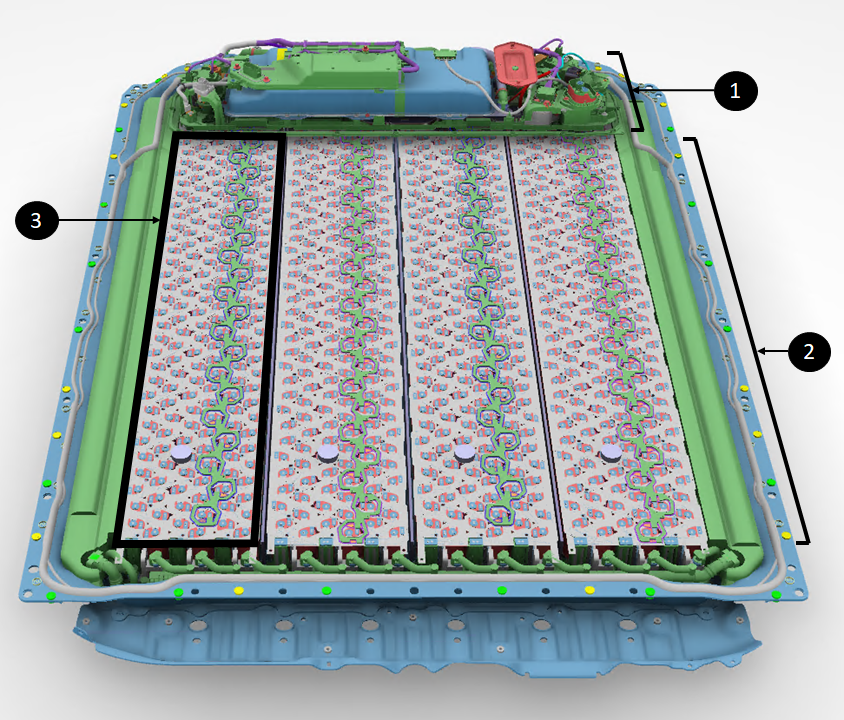
The HV platter is the large area of the battery that is below the Ancillary Bay and inside the enclosure. It contains the cell-arrays, high voltage distribution links, and thermal elements of the HV battery. The High Voltage Devices of the HV battery are located in the Ancillary Bay. The only piece of HV electronic that is not in the Ancillary Bay is the set of Battery Monitoring Boards (BMB) which are located in the cell-arrays of the HV battery.
The platter contains all the cells which have a minimum voltage of 2.5V closed circuit and a max voltage of 4.2V open circuit. With a s-count of 96, the HV battery has a minimum voltage of 240V and a maximum of 403V.
Warning
The top cover is not removeable in service. The top cover is bonded to the enclosure and all cell-arrays with adhesive. The cover cannot be removed without being damaged. Only specifically trained personnel shall remove the HV battery cover.
Note
For more information about the Ancillary Bay, refer to the Ancillary Bay Theory of Operation.
 |
|---|
| 1. Ancillary Bay 2. Platter 3. Cell-Array |
| Main section of the HV battery (Cover Lifted) |
Ancillary Baylink
The Ancillary Bay contains most of the HV electronics in the HV battery used to control the HV system of the vehicle. This includes:
- Powering up the HV system of the vehicle
- Charging the vehicle HV battery
- Providing power to the low- voltage system
- Managing power available for the HV system
- Managing HV system failures
- Managing thermal condition of the HV battery
The Ancillary Bay allows access to most components of the HV battery, aside from cell-arrays and the platter thermal cooling system.
 |
|---|
| 1. Ancillary Bay with Ancillary Bay Cover On |
| Location of Ancillary Bay - Cover Attached |
 |
|---|
| 1. Ancillary Bay Components with Ancillary Bay Cover Off |
| Location of Ancillary Bay - Cover Removed |
The Ancillary Bay contains:
| HV Device | Purpose |
|---|---|
| Power Conversion System (PCS) |
|
| High Voltage Controller (HVC) | Includes the High Voltage Battery Management System (HVBMS) and High Voltage Processor (HVP) |
| Fast Charge Contactors | Connect the HV battery to the charge port for DC charging |
| Pack Contactors | Connect HV from modules to vehicle powertrain |
| HV Shunt | Measures HV current |
| HV Pyro-disconnect |
|
| Charge inlet connector | Connects PCS input to the charge port |
| HV fuses |
|
Located under the rear passenger seats, the Ancillary Bay cover can be accessed and removed without taking out the HV battery.
A dedicated cover on the Ancillary Bay provides access to the pyro-disconnect, allowing for replacement without removing the entire Ancillary Bay cover.
High Voltage Interfaceslink
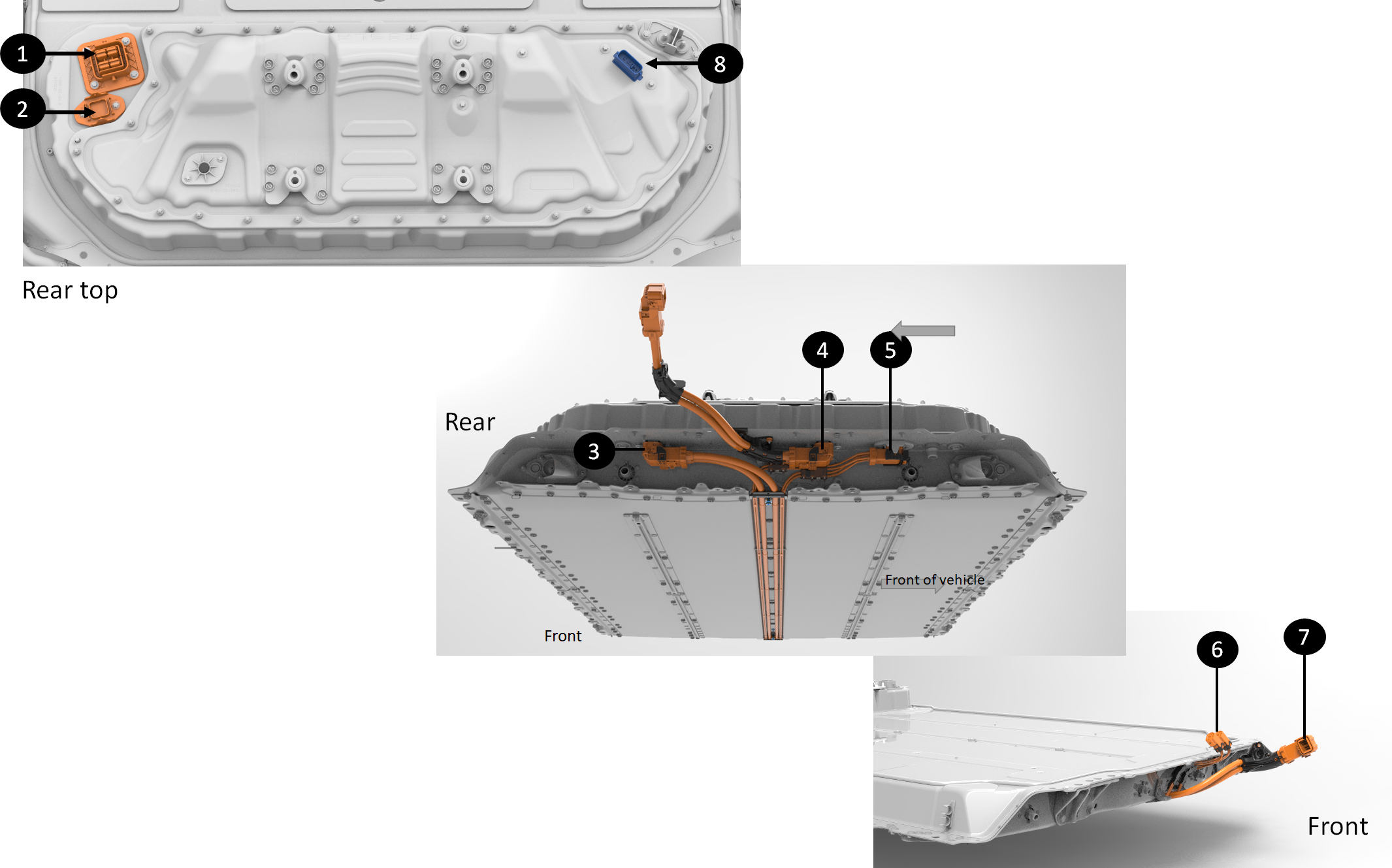
The HV battery integrates the functionality of the on-board charger, DCDC converter, High Voltage Junction Box (HVJB), and Front Junction Box (FJB)HV distribution to receive and transmit signals to most powertrain electronic control units (ECUs) in the vehicle and powers on bank of the low- voltage system through the power conversion system. To achieve all this, the following interfaces exist on the HV battery:
 |
|---|
| 1. Charge inlet connector 2. Three phase charge inlet connector 3. Front Drive Unit connector at HV battery (connector reference FDU-HV-AT-HVBATT) 4. Rear drive unit connector at HV battery (connector reference RDU-HV-AT-HVBATT) 5. Four pole HV connector for ancillaries (PTC heater and compressor) - (connector reference CMP-HV-AT-HVBATT) 6. Ancillaries front HV connectors (only one connector for cars with heat pump and without PTC heater) 7. Front drive unit HV connector (connector reference FDU-HV-AT-FDU) 8. Logic connector at Ancillary Bay (x098) |
| HV battery interfaces |
Cell-Arrayslink
Specificationslink
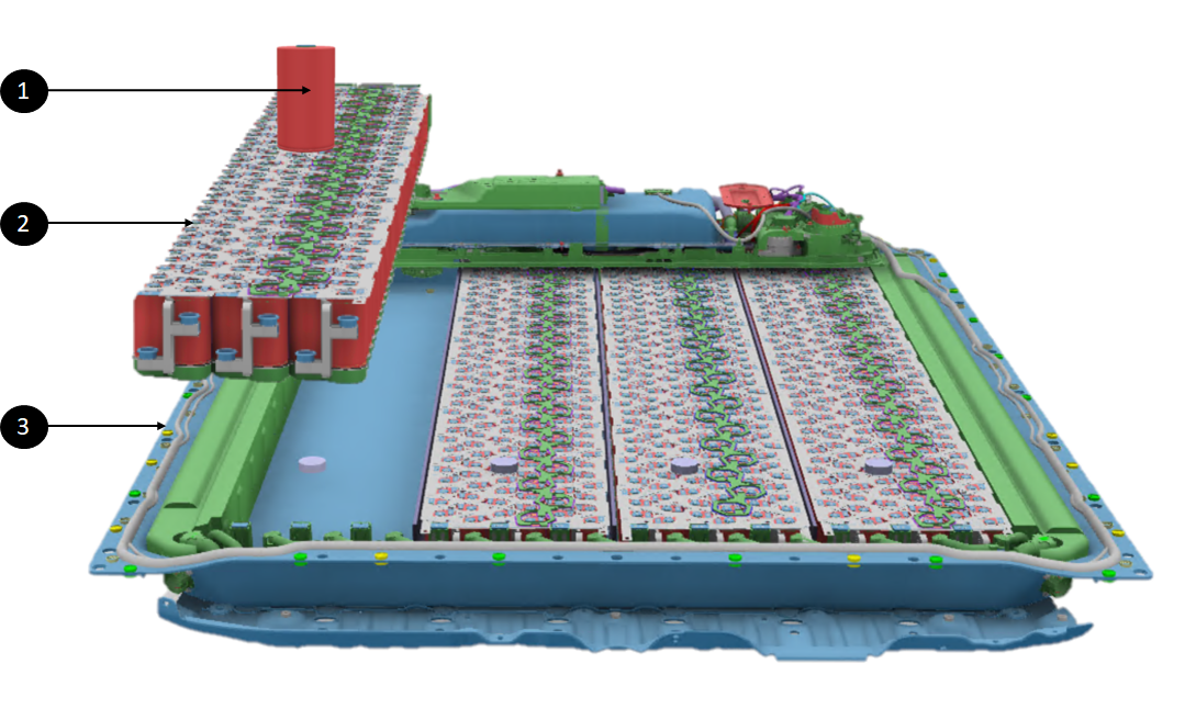
The HV battery is made of 4 independent cell-arrays installed length wise in the platter. The cell-array contains the cells of the HV battery and it is the source of energy and power for the vehicle. Each cell-arraycell-array
Each 4680 based cell-array is made of 24 bricks in series which sums up to a voltage of 86V per cell array. The single LFP base cell-array is made of 105 bricks in series.
 |
|---|
| 1. Battery cell 2. Cell-Array 3. Platter |
| HV Platter - Cell-Array to cell |
Operationlink
Cellslink
Cells are the source of energy and power for the vehicle.
The HV battery has an internal structure of lithium ion cells linked together in combination of parallel and series to reach the desired level of energy and power required.
The lithium ion cells have a high energy density (Wh/kg), about 2 to 3 times the energy density of a nickel-metal hydride battery and 6 times the energy density of lead acid battery. Lithium ion cells are agnostic to charge and discharge patterns. When not in use, lithium ion cells self-discharge and have a flat discharge curve, meaning they have linear power capability even at half charge level.
Rechargeable batteries perform reversible electrochemical reactions at the battery’s positive and negative electrodes. The battery is charged by applying an electric current.
During discharge, lithium ions de-intercalate from the negative electrode and move through a separator to intercalate in the positive electrode. When charging, the reverse occurs. Lithium ions de-intercalate from the positive electrode and move through a separator to intercalate in the negative electrode.
 |
|---|
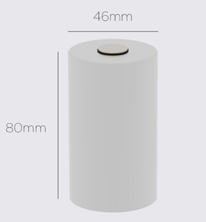
| 4680 cell |
The cells used in the HV battery have a 4680 (Gigafactory Austin) or Blade style (Gigafactory Berlin)
| HV battery Generation | Configuration | Cell Type | S-Count | P-Count | Total Cells in Pack |
|---|---|---|---|---|---|
| Gen 2 | Standard Range 2170 | 2170 | 96 | 31 | 2976 |
| Gen 2 | Standard Range LFP | LFP | 106 | 1 | 106 |
| Gen 2 | Standard Range LFP2 | LFP | 102 | 1 | 102 |
| Gen 2 | Mid-Range | 2170 | 96 | 37 | 3552 |
| Gen 2 | Long Range | 2170 | 96 | 46 | 4416 |
| Gen 2 | Structural Standard Range | Blade | 105 | 1 | 105 |
| Gen 2 | Structural Dual Motor | 4680 | 96 | 10 | 960 |
Bricks in Bandolierslink
A brick is a group of cells connected in parallel. Linking cells in parallel adds current from each cell to increase current capability and the amp hour count (the unit for measuring the energy capacity of a battery).
The bricks are connected in series in a cell-array to increase voltage. The cell-arrays are also chained together in series to further increase voltage and power capability.
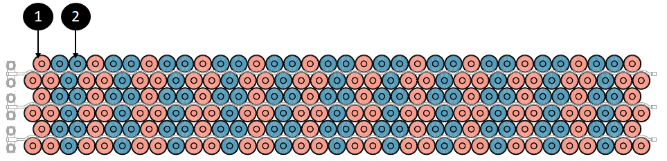
Each brick is spread on the entire width of the cell-array for even repartition of current among the cells. Nine cells from one brick will be connected to the cell collector via their positive terminal and nine cells from the next brick will be connected to the cell collector via their negative terminal.
A bandolier refers to one or two strings of cells against a cooling tube. A cell-array is made of four7 bandoliers.
The cells in the bandolier are positioned vertically and oriented in the same direction (one brick with anode facing up and the next brick with anode facing up).
Cell-arrays are separated by a cross member running length wise in The HV battery. There are three inner longitudinals between each cell-array and two outer longitudinals between the outer cell-arrays and the edge of the battery. The outer longitudinal protects the cell-arrays during side vehicle impacts.
The top of the cells of each brick are spot welded to two current collectors. The center button of the cell is the positive terminal of the cell, and the outside can of the cell is the negative terminal.
- One current collector is connected to two bricks (positive of one brick and negative of the other one).
- A single collector will be connected to 18 cells.
- Half of a collector will be connected to the can of the cells (anode) and the other half are connected to the center tab (cathode).
The current collector performs the following functions:
- Electrically interconnects cell-arrays in a series of parallel groupings,
- Distributes current between all cells in a given parallel grouping,
- Allows terminal voltage sensing, at a single point, for all cell in a given brick,
- Conducts peak and continuous operating currents between each cell and array,
- Fusing protection for HV shorts.
 |
|---|
| 1. First brick 2. Next brick |
| Brick Layout in a Cell-Array |
Cell and Brick Numberinglink
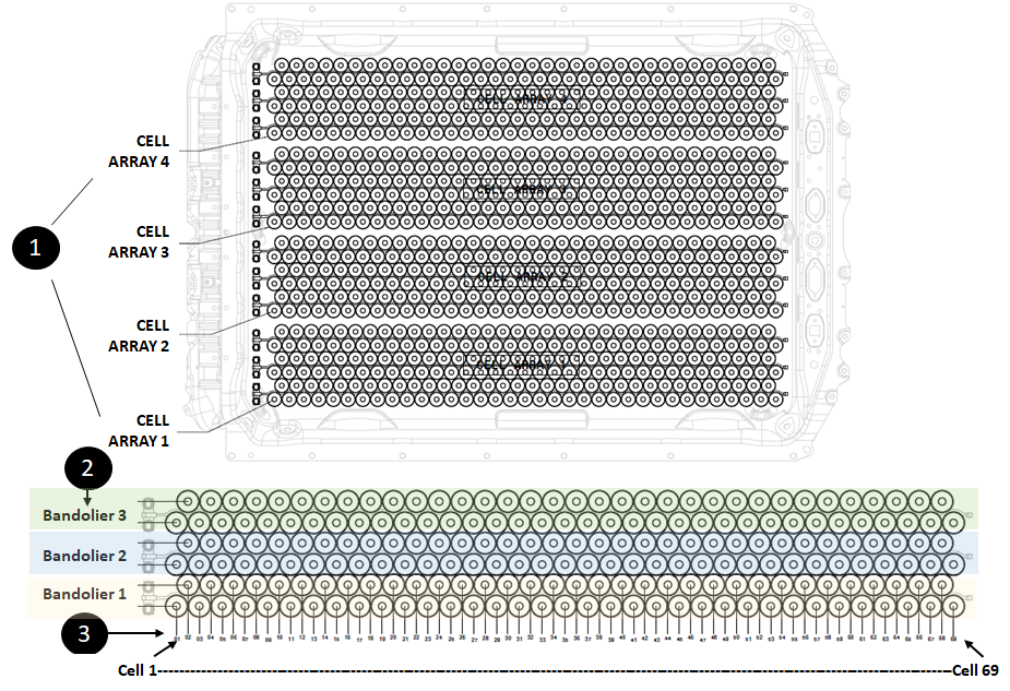
Cell and brick numbering is the link between software and the physical pack. The numbering hierarchy in the structural HV battery is as follows:
- Cell-Arrays are numbered from 1 to 4.
- Bandoliers in each cell-array are numbered from 1 to 3.
- Each cell within a bandolier is numbered from 1 to 69
 |
|---|
| 1. Numbering of Cell-Arrays 2. Numbering of Bandoliers per Cell-Array 3. Numbering of Cells per Bandolier |
| Numbering of Cell-Array, Bandolier, and Cells in the HV battery |
High Voltage Chainlink
Current and power accumulate along the cell-array, beginning at the first brick on the most negative end and growing to the positive end of the array, with HV terminals at each end to facilitate connection.
Note
The front terminals are designed to fuse under short circuit events at the cell-array level.
For detailed information on how the voltage builds up in the HV battery, refer to the HV Architecture Theory of Operation
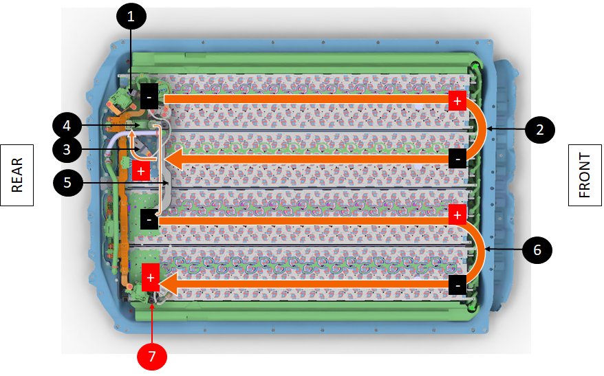
Voltage build-up within structural HV battery goes as follows:
- HV starts from Cell-Array 1 (the most negative side) located on the front left corner of the HV battery.
- The negative HV terminal of Cell-Array 1 is connected to the negative pack-contactor.
- Voltage builds up brick to brick within Cell-Array 1 toward the front of the cell-array and HV battery where the front HV jumper takes the voltage to Cell-Array 2.
- Voltage builds up brick to brick within Cell-Array 2 toward the rear of the cell-array and HV battery where a rod takes the HV link to the inside of the Ancillary Bay.
- A bus bar takes the current toward the pyro-disconnect via joint that is bolted to the pyro-disconnect.
- The pyro-disconnect opens the HV loop when the high voltage processor (HVP) fires it. A bus bar then takes the current to the negative HV terminal of Cell-Array 3.
- Voltage builds up brick to brick within Cell-Array 3 toward the front of the cell-array and HV battery where the last switch back via a front terminal jumper takes the voltage to Cell-Array 4.
- HV travels back to the rear of the HV battery where it will find the terminal rod of Cell-Array 4, which connects to the positive pack-contactor via a bus bar.
 |
|---|
| 1. Most negative HV terminal at negative contactor 2. Front HV jumper between Cell-Array 1 and 2 3. Bus bar from Cell-Array 2 to pyro-disconnect 4. Pyro-disconnect 5. Bus bar from pyro-disconnect to Cell-Array 3 6. Front HV jumper between Cell-Array 3 and 4 7. Most positive HV terminal at positive contactor |
| Diagram of Voltage Build-Up |
The HV battery contactors connect or disconnect the HV battery's high voltage to the vehicle's powertrain, while the HV pyro-disconnect is located between Cell-Array 2 and 3. The HVC will trip the pyro fuse if a short circuit is detected inside or outside the HV battery, or if a condition requires immediate power cutoff.
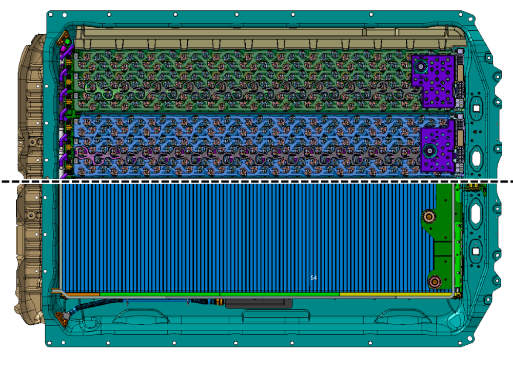
Blade Cell High Voltage Chainlink
The Blade cell structural battery contains 105 cells in series. Each cell takes the place of one brick, as with CATL. The cells are prismatic (rectangular shaped), just as with CATL. However, the cells are also long and travel across the enclosure.
 |
|---|
| Illustration of HV Chain inside Blade cell HV battery versus 4680 |
Serviceabilitylink
Cell-Arrays are not serviceable because they are embedded within the platter area, making them inaccessible due to the structural HV battery's bonded top and bottom enclosures.
Battery Management Boardlink
Specificationslink
A BMB is a Printed Electrical Circuit Board (PCBA) with various electrical components on it. The primary functions of a battery monitoring board (BMB) are:
- Measuring voltages of the bricks in a cell-array
- Measuring temperatures of cell-arrays in one or several locations
- Balancing bricks charge level amongst other bricks
BMBs are connected to both sides of each brick in a cell-array.
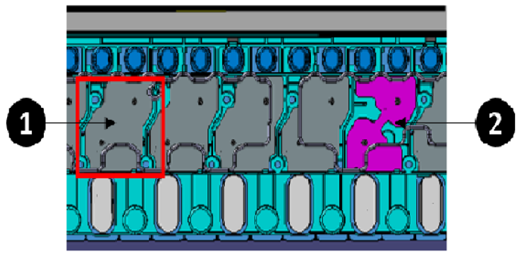
The wires linking current collectors to BMBs are consolidated into a flexible ribbon cable called the Voltage Sense Harness (VSH). Blade cell HV batteries use busbars to connect cells, replacing wire bonds and VSH wiring, with some busbars featuring a thinner center for added protection against fusing.
 |
|---|
| 1. Regular Busbar 2. Fusing Busbar |
| Busbar Interconnects |
 |
|---|
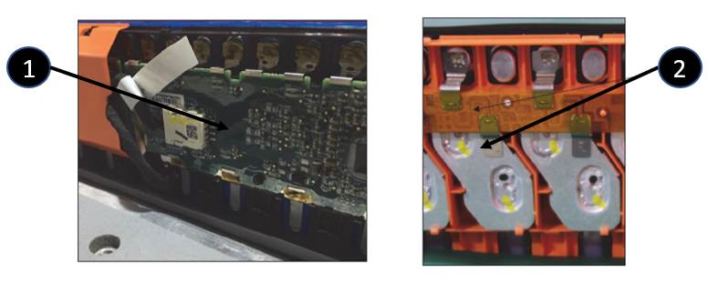
| 1. BMB 2. Zoom on a single BMB board |
| Battery Monitoring Board Overview |
 |
|---|
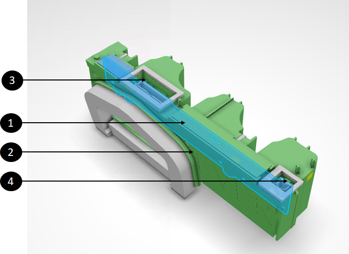
| 1. BMB (inside the housing, in blue on the rendering) 2. BMB plastic housing 3. Female connector at BMB for voltage sensor harness (VSH) 4. Female connector at BMB for daisy chain communication |
| BMB Location in the Brick HV batteries |
 |
|---|
| 1. BMBs (along one side of blade cell terminals) 2. Busbar interconnects (along other side of blade cell terminals) |
| BMB and Busbar Locations in the Blade Cell HV batteries |
BMBs have two thermistors mounted directly on the PCBA close to where the bandolier cooling tubes contact the BMB PCBA. The temperature of the cell-array can be measured without requiring extra wiring between BMBs other locations on the cell-array.
BMBs connect to each other via a daisy chain which itself is connected to the high voltage controller (HVC). Temperature and brick voltage measurements from BMBs travel on this daisy chain to the HVC. If the daisy chain is interrupted or cut anywhere, the data from BMBs can travel the other direction to the HVC.
BMBs are equipped with an analog to digital converter (ADC) to get the brick voltages and temperatures into a format that can be sent on a digital communication protocol. They also embed a multiplexer to send each measurement in sequenced order on the daisy chain.
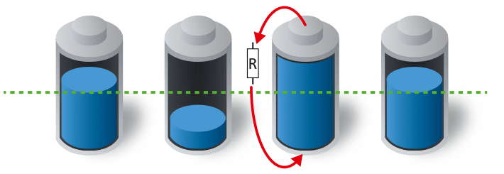
BMBs contain one power resistor and Field Effect Transistor (FET) per brick. The FET enables a resistor to be connected in parallel with the brick, allowing for controlled energy dissipation and balancing of brick charge levels in the HV battery. BMBs only perform this passive balancing and do not charge the least charge bricks (known as active balancing).
 |
|---|
| Each cell on the picture is equivalent to a brick |
| Passive Balancing with Discharge of Most Charge Bricks |
Operationlink
The BMB functions of measuring cell-array voltage and temperature and balancing brick charge levels are critical to operating the HV battery and the vehicle. A BMB not operating as expected can prevent vehicle charging or starting, and may also cause reduced power or graceful power-off with a 30-second warning while driving to pull over before contactors open.
BMBs continuously monitor temperatures and brick voltages during charging, driving, and low-voltage system support. When the vehicle is asleep, the HVC wakes the BMBs every 10 minutes for them to report measurements and ensure brick health.
BMBs will balance the bricks when the HVC enables balancing. The HVC enables brick balancing only when the charge level of bricks has enough charge or voltage difference, and the least charged brick is above a certain threshold.
BMBs don't have embedded advanced micro processing capabilities. Their duty is to sense voltage, temperatures, and be able to put a resistor across a brick for balancing. All the processing happens in the HVC, which requires the measurements provided by the BMBs. To get the data from BMBs to the HVC, there is a daisy chain leaving the HVC, going through all BMBs in series and back into the HVC.
The daisy chain communication is bi-directional. If the daisy chain is cut anywhere, all BMBs can still communicate to the HVC.
Note
Model 3 and Y HVBMS is named HVBMS in UDS commands. This is to differentiate from Model S and Model X UDS commands nomenclature.
Serviceabilitylink
BMBs not serviceable because they are embedded within the platter area, making them inaccessible due to the structural HV battery's bonded top and bottom enclosures.
High Voltage Battery Thermal Managementlink
Specificationslink
The HV battery uses liquid based thermal systems to keep battery cells at their optimized temperature and to control heat generated during conversions between AC/DC and AC/DC power. The thermal systems are split between cooling the Power Conversion System (PCS) and the cells within the cell-arrays.
Power Conversion System Thermal Looplink
The PCS cooling loop consists of:
- Coolant passthrough to connect external coolant lines to the ones going to the PCS inside the HV battery.
- Inlet coolant hose bringing external coolant to the PCS.
- The PCS cooling plate on which electronic components of the PCS are mounted.
- Temperature sensors on the PCS Printed Electrical Circuit Board (PCBA).
- Outlet coolant hose to push the warm coolant back out to the external cooling system.
- Temperature sensor at the coolant inlet into the HV battery.
The PCS coolant inlet and outlets are located at the front of the HV battery directly through the ancillary bay cover.
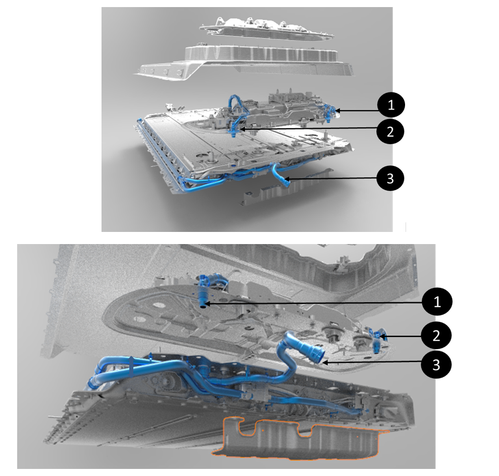 |
|---|
| 1. Coolant outlet out of the ancillary bay 2. Coolant inlet into the ancillary bay 3. Coolant inlet into the HV battery for the ancillary bay |
| PCS / Ancillary Coolant Loop |
Cell-Array Thermal Looplink
The platter cooling system consists of:
- Coolant passthrough to connect external coolant lines to the ones to the cell-arrays.
- Inlet coolant manifolds to split the coolant flow to all the cooling tubes of the HV battery.
- Cooling tubes thermally connecting the cells to the coolant.
- Outlet manifolds to collect the coolant back from all the cooling tubes .
- Outlet coolant hose to push the coolant back out to the external cooling system.
- Temperature sensors on each BMB.
 |
|---|
| 1. Module coolant outlets 2. Coolant line from ancillary bay to rear drive unit 3. Coolant inlet to Ancillary bay |
| Coolant Ports of the HV Battery Platter |
Operationlink
Power Conversion System Thermal Looplink
The PCS requests a desired temperature to VCFRONT. VCFRONT aggregate all the component temperature requests and appropriately set the pumps speeds and the coolant loop state.
The coolant coming from the PCS inlet passthrough will travel in the PCS cooling plate where heat will be transferred from the PCS electronics to the coolant. The coolant, from the hot electronics, will exit the PCS to get back to the vehicle cooling system where heat will be transferred to the outside air of other components that requested heat.
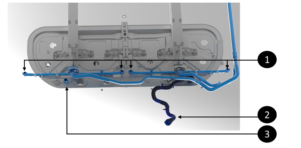
Cell-Array Thermal Looplink
The HVC calculates the desired coolant temperature based on brick State of Charge (SOC), temperatures, and vehicle state, sending it to VCFRONT. VCFRONTaggregates this data to control pump speeds and coolant flow. The output is either hot or cool coolant traveling through the cooling tubes of the platter.
In the cell-arrays, each cell has about a third of its surface in contact with a cooling tube. The entire height of any cell contacts the cooling tube to ensure homogenous temperature along the cell.
Each cooling tubes running length
 |
|---|
| Platter / Module / Cell Cooling Flow |
Serviceabilitylink
The PCS cooling system is serviceable:
- The PCS can be replaced if the cooling plate has a blockage or is leaking.
- The coolant hoses from the Ancillary Bay cover to the PCS are also replaceable if damaged.
- The coolant hoses and passthroughs set up on the HV battery avoids any spillage in the Ancillary Bay upon disconnection and avoid having to drain coolant for other service actions in the Ancillary Bay that do not involve PCS.
- Service can disconnect coolant connections at the passthrough (coolant will leak outside) and plug the passthroughs. From there, the PCS and with the coolant hoses connected can be removed as one unit preventing any spillage.
The platter thermal system is not serviceable because its components are embedded within the platter area, making them inaccessible due to the structural HV battery's bonded top and bottom enclosures.
Overpressure / Overtemperature Dissipationlink
Specificationslink
The HV battery needs to be able to handle thermal runaway events internal to the HV battery in a controlled manner. Those events are sometimes caused by:
- Significant external damage to the HV battery causing cell penetration or deformation
- An internal coolant or other liquid flood. In rare cases, it can also be caused by some internal failures in the HV battery.
The HV battery features the following hardware to control runaways:
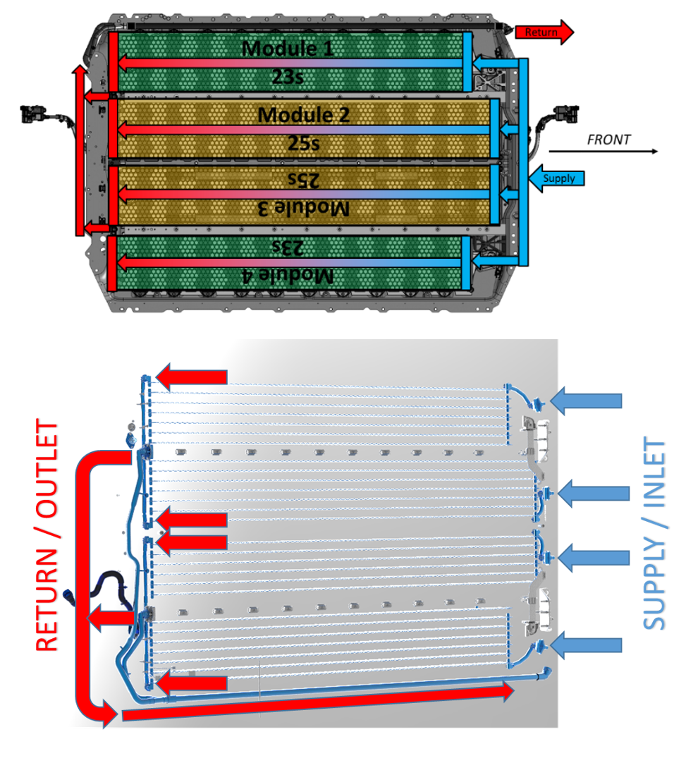
- Pack venting to allow controlled release of internal HV battery overpressure. The HV battery uses vents to allow the pressure in the enclosure to vent if pressure builds up inside the HV battery.
 |
|---|
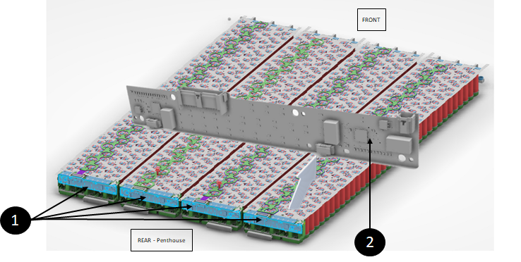
| 1. Four vent assemblies at the rear of the HV battery |
| HV Pack Vents |
- Flood ports to allow automated drainage of any liquids trapped in the HV battery. Flood ports open when liquid contacts the inside of the flood port on the HV battery side (and not when liquid contacts the section of the flood port sticking outside of the HV battery).
Note
The number of flood ports depends on the pedigree of the structural HV battery. The first iteration did not have any flood ports on the enclosure.
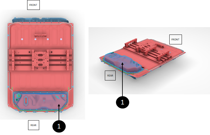
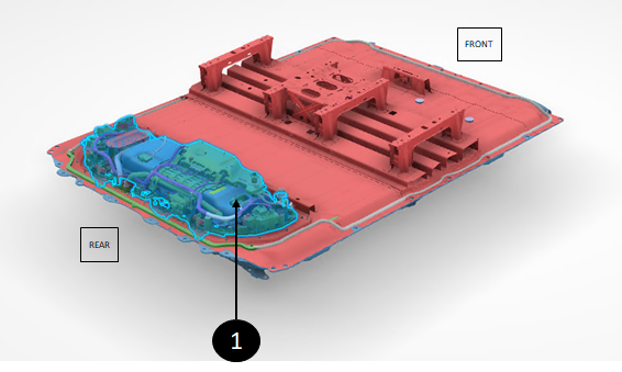
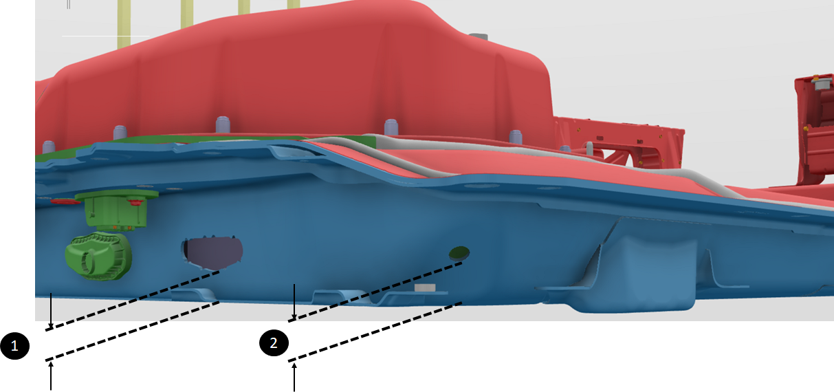
Most commonly, the structural HV battery has four flood ports located in the rear, two at the rear extreme corners for platter flood, and two on the Ancillary Bay floor to drain the Ancillary Bay .
 |
|---|
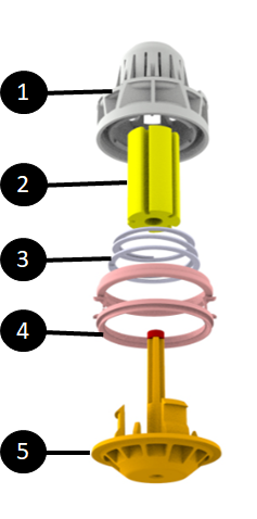
| 1. Flood port basket housing preventing blockage 2. Cellulose element 3. Spring load allowing the valve to shoot down when cellulose element dissolves 4. Flood port carrier 5. Valve pushed down in presence of liquid |
The basket housing is designed to prevent anything from blocking the flow of liquid by catching any large debris that would otherwise flow into the hole and plug it.
Note
The flood ports of the platter are protected with a dust cover. See below.
 |
|---|
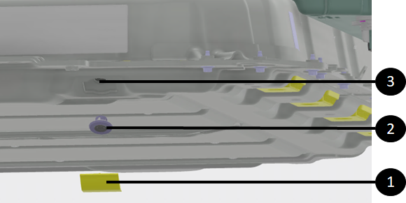
| 1. Dust cover to protect the flood port 2. Flood port 3. Opening in the enclosure where flood port seats to let liquid out |
 |
|---|
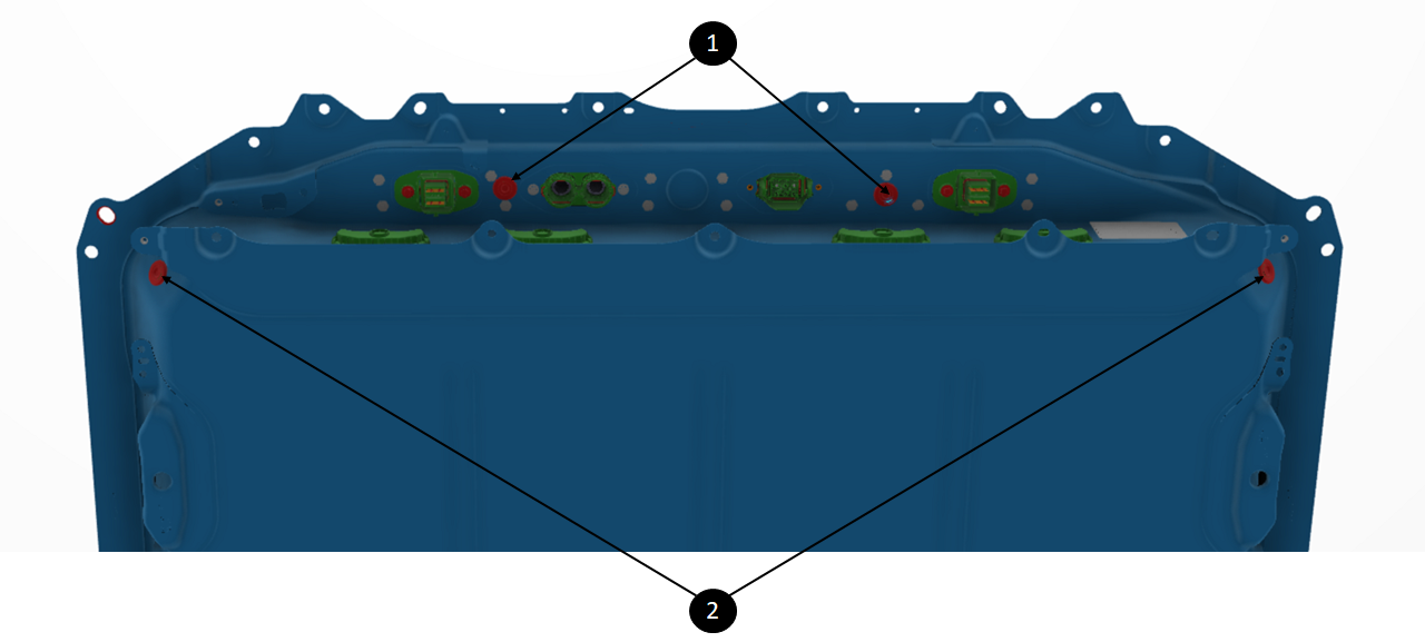
| 1. Ancillary Bay flood ports 2. Flood port on rear bottom corners of the platter enclosure |
| Flood port location |
The cellulose-based ring is not serviceable. Once the flood port has been opened, it needs to be replaced. The flood port is replaceable in service from the outside of the HV battery. It can be rotated out while pulling. It is likely that a plastic tab will break and fall into the HV battery, which is okay.
The flood port design helps:
- Prevent hazardous pooling of fluid in Ancillary Bay volume.
- Seal against liquid/gas passage into Ancillary Bay volume from outside.
Operationlink
Pack Ventslink
If pressure builds up inside the HV battery, the vents are designed to open outward, allowing pressure to escape the enclosure if it builds up inside. It is a one-way vent, designed so that air or other environmental debris will not enter the HV battery. The vent will disintegrate under high heat. Once disintegrated, it creates a large opening to allow faster expulsion of high-pressure gases inside the HV battery.
The structural HV battery has a dedicated space under the cell-array for pressure and heat to escape to the rear vents, and electrical isolators between arrays to reduce propagation risk.
Flood Portslink
Any long standing liquid inside the HV battery is concerning, it could overtime create soft short between cells that could generate uncontrolled heat. Flood ports automatically drain any liquid inside the HV battery to below cell-arrays. A flood port is a mechanical one way valve that opens in presence of liquid. It has a cellulose element that expands upon contact with liquid. This causes a plastic retainer to release a spring that opens the valve to let the liquid drain from the Ancillary Bay . The flood port design helps:
- Prevent hazardous pooling of fluid inside the HV battery volume.
- Seal against liquid/gas passage into the HV battery from outside.
The flood port is one time use, once it opens, it cannot close back and needs to be replaced. However, the flood ports are replaceable in service from the outside of the HV battery by twisting and pulling. It is likely that a plastic tab will break and fall into the HV battery, which is okay.
On the structural HV battery, removing the vent assemblies will not aid in liquid removal, as there is a gap between the assemblies and the battery floor. A significant amount of liquid would be required to reach the bottom of the vent assemblies inside the HV battery. The HV battery has been designed to handle some liquid inside and the cell-array is raised up off the floor of the enclosure. If the vehicle is level, it would take around 40 liters of liquid to reach the cell-array tub, more than the vehicle's total coolant volume. If the vehicle is tilted, then coolant could leak in a cell-array tub and reach cells. To drain liquid from an HV battery, rotate and remove the 4 flood ports (if equipped), and tilt the vehicle or HV battery rearward to allow liquid to exit via the ports.
Serviceabilitylink
Both vents and flood ports are replaceable in service if damaged, missing or opened. They snap on to the enclosure from the outside of the HV battery (flood port require a twist before being pulled out)
Note
If it is suspected that a HV battery has liquid in the platter, service is responsible for draining the liquid as soon as possible.
Even when the flood port opened and drained some liquid, more will still be present in the HV battery as the flood port is not flush with the bottom of the enclosure.
 |
|---|
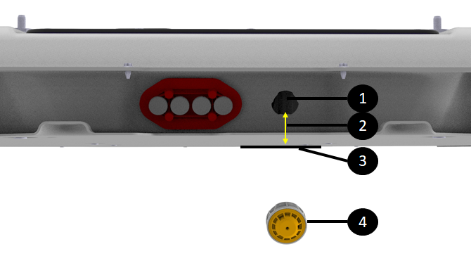
| 1. Hole opening with flood port opened 2. Lip between bottom of hole and enclosure floor 3. Enclosure floor 4. Flood port removed |
| Lip between flood port hole and enclosure floor |
To drain the liquid not emptied by flood ports, it is recommended to use a screwdriver or thin plastic trim tool to pop off the 5 side umbrella valves. Once the umbrella valves are removed, the vehicle should be tilted on the passenger side (LHD vehicles) while keeping it as horizontal as possible to allow liquid to drain out of the HV battery.
Removing the breather assembly and tilting the vehicle toward the rear would not work, as the inter-module bays are sealed. That procedure would only drain the rearmost module bay.
 |
|---|
| 1. Lip between vent assembly opening and enclosure floor 2. Lip between flood port opening and enclosure floor |
| Lip Between Enclosure Vent and Flood Port Holes and Enclosure Floor |
To drain the liquid not emptied by flood ports, it is recommended to use a screwdriver or thin plastic trim tool to pop off the 3 vent assemblies. Once the umbrella valves are removed, the vehicle should be tilted toward the rear and either passenger or vehicle side as much as possible to allow liquid to drain out of the HV battery via a flood port corner hole.
Removing the breather assembly and tilting the vehicle toward the rear would not work, as the inter-cell-array bays are sealed. That procedure would only drain the rearmost cell-array bay.