Safety and Restraintslink
Last updated: December 02, 2024
Introduction and Overviewlink
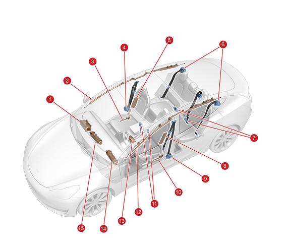
Location of Airbag and Seat Belt Componentslink
 |
|---|
| 1. Front passenger airbag 2. Curtain airbag - RH 3. Lap belt pretensioner - RH 4. Seat belt - 1st row - RH 5. Passenger seat mounted airbag 6. Shoulder belt pretensioners - 2nd row 7. Seat belt buckles - 2nd row 8. Driver seat mounted airbag 9. Seat belt - 1st row - LH 10. Lap belt pretensioner - LH 11. Seat belt buckles - 1st row 12. Curtain airbag - LH 13. Driver airbag - LH 14. Knee airbag - LH (if equipped) 15. Knee airbag - RH (if equipped) |
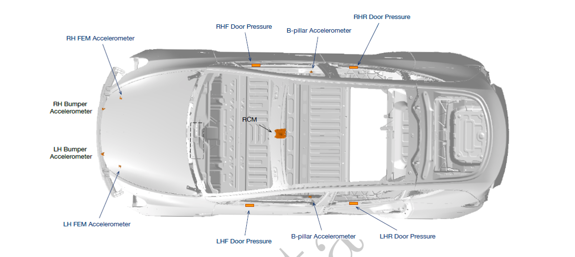
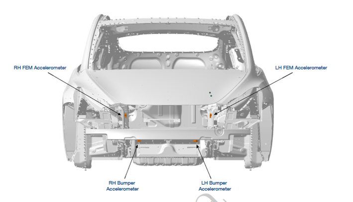
Location of Impact Sensorslink
 |
|---|
| 1. Front end module sensor - RH 2. Front door pressure sensor - RH 3. B-Pillar sensor - RH 4. Rear door pressure sensor - RH 5. Rear door pressure sensor - LH 6. B-Pillar sensor - LH 7. Restraint Control Module (RCM) 8. Front door pressure sensor - LH 9. Front end module sensor - LH 10. Bumper accelerometer - LH 11. Bumper accelerometer - RH |
Overviewlink
The Tesla Supplementary Restraint System (TSRS) is designed to work in conjunction with the seat belts. These devices supplement, but DO NOT replace, the protection afforded by the seat belts. Seat belts are proven to be the single most effective safety device in a vehicle, and should always be worn. Properly worn seat belts also ensure that the occupant is seated in the optimum position to benefit from the full effectiveness of the airbags and seat belt pretensioners.
The Model Y has a variety of airbags which, when combined with seat belts are intended to safely dissipate the occupant’s kinetic energy during an impact. The amount of kinetic energy airbags must absorb depends on the velocity of the vehicle and the mass of the occupant. Advanced multi-stage airbags like those in Model Y front row are able to adjust the energy absorption for different speeds or passenger sizes. Seat sensors like the Occupant Classification System (OCS) and seat track position sensor give an indication of the passenger mass and location while crash accelerometer and pressure measurements allow for an understanding of the impact speed. The information is continually fed into the Restraint Control Module (RCM) where, in the event of a crash, it can determine the appropriate energy absorption needed from the seat belts and airbags.
Seat belts in the front row are equipped with a variable load limiter, which adjusts the amount of energy that the seat belts absorb from the occupant. To minimize the risk of occupant injury the load limiter can be deployed to lessen the maximum tension in the seat belts. When load limiters are deployed the energy absorbed by the seat belts is decreased, which allows the airbags to absorb occupant energy more effectively. The system is only deployed in frontal impacts where the airbags are most effective. In cases with only lateral motion or any rear impact, the seat belts absorb as much energy as possible.
Seat belt pretensioners are used to remove slack from the seat belt which helps to absorb occupant energy. Front row seats have shoulder and lap belts with pyrotechnic retractors located in the lower B-pillar trim and lap pretensioners mounted to the seat frame. Second row seats have a shoulder belt with a pyrotechnic retractor. The middle seat does not have a pretensioner.
The first row and second row outboard occupants are protected in crashes with lateral motion (side, angled or offset type crashes) by side curtain airbags. The curtain airbags deploy down from the upper trim area. Seat airbags inflate from the outboard seat bolsters to soften occupant hip and torso contact with the door trim in the first row. In North American markets vehicles are equipped with knee airbags, which deploy in frontal crashes. However, the knee airbag will not deploy when a belted occupant is seated in the passenger seat, and the seat is forward of a pre-determined point in seat track travel (closer to the airbag module). This is in order to protect the occupant from being too close to the airbag during deployment.
In the event of a collision with the drive rail on, the pyrotechnic fuse is deployed to isolate high voltage from the HV Battery. All crash modes including: front, side, rear or roll, which exceed programed threshold will trigger the pyrofuse. The fuse disables high voltage by breaking continuity.
All deployable safety systems such as airbags and seat belt pretensioners are single use pyrotechnic devices and must be replaced after deployment. All partially-deployed devices (except load limiters) will completely dispose of their pyrotechnic component within a short period of time of pretensioner deployment. Seat airbag deployment will require a full seat replacement in the event of deployment. While deployed safety devices are designed to be inert after a crash to protect occupants and first responders, any pyrotechnic device should be handled with all proper procedures and care according to the vehicle Service Manual.
Note
Refer to Collision Repair Procedure SRS Inspection and Component Replacement.
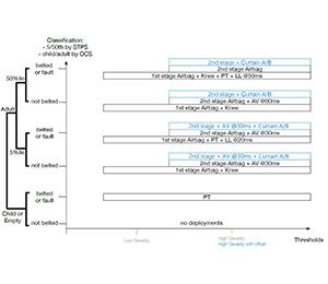
where deceleration above calibration threshold with force directed mostly along the direction of travel. The control module will deploy pyrotechnic fuse, pretensioners where the seating position is reading faulted or buckled, knee airbags, load limiter selectors, and stage 1 front body airbags. To avoid stress on the occupant, stage 2 is not deployed and goes to disposal to protect occupants and first responders. Side airbags are NOT deployed. The RCM continues to monitor for any additional impacts, and can still deploy remaining systems in any later side impacts or rollover. - Flat frontal impact (high speed): Impact velocity above a certain speed with force directed mostly along the direction of travel. The same systems are deployed as a low speed frontal, but front airbags deploy both stage 1 and stage 2 for faster positioning and greater stiffness. The RCM will use information about the mass of occupant to determine the appropriate deployment strategy. The front airbags also deploy the active vents, if equipped, to lessen absorption energy. - Angled frontal impact (high speed): Impact velocity above a certain speed
Starting and Drivinglink
The airbag warning indicator displays for six seconds when the vehicle is switched on as a system check. After the system check, if there is no active fault, the indicator turns off and stays off. If there is an active fault, the indicator turns off for one second and then turns back. Some faults will latch the light on for the remainder of the drive cycle, while others can clear and the light will shut off. Consult Toolbox for airbag light behavior of specific faults.
The front seat belt indicator and chime are controlled by the restraint control module based on input from the Seat Belt Reminder (SBR) switches and the OCS (OCS). The passenger seat SBR and the OCS are inputs to the RCM.
If the seat belt is fastened during any of the three stages, the chime stops and the indicator turns off.
The center display shows all occupied and unbuckled seats on a bird’s eye view of the vehicle. The occupancy sensors can be triggered by any object above approximately 30 lbs.
Component Specificationslink
Model Y is equipped with a Supplementary Restraint System (TSRS). The system comprises the following components:
- Restraint Control Module
- Occupant Classification System
- Occupancy sensors
- Seat track position sensor
- Only available in North American market.
- Impact / Pressure sensors
- Passenger seat position sensor
- Seat belt buckle switch
Restraint Control Modulelink
 |
|---|
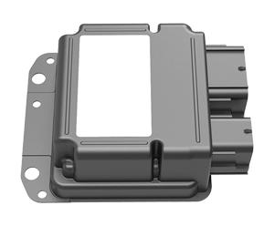
| Restraint Control Module |
 |
|---|
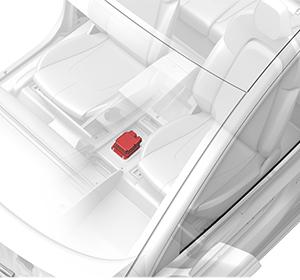
| Restraint Control Module Location |
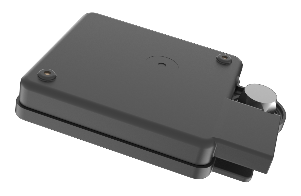
The supplementary restraint system is controlled by the universal Restraint Control Module (RCM), which includes fault detection and warning circuits. If a fault is detected, an indicator light in the instrument panel notifies the driver. Alerts (with the Electronic Control Unit (ECU) prefix "RCM2") are also retrievable using Vitals (via Toolbox) or the vehicle's center display in Service mode.
The RCM is calibrated specifically for the vehicle model. It contains accelerometers and gyroscopes to measure forces acting on the vehicle, and circuits for monitoring the condition of all pyrotechnic devices. It is the primary device that commands the deployment of all Tesla Restraint System components. During a deployment the system runs a current through individual components to trigger the pyrotechnics. Each stage and part has its own independent wire loop for this triggering signal.
The RCM monitors the TSRS's electrical components and circuitry when the drive rail is on. The RCM uses an internal six axis inertial measurement unit (IMU) to monitor all 3 angular velocities, as well as 3D velocity and acceleration changes in the vehicle. The module is located under the center console near the vehicles center of gravity to sample the motion of the entire vehicle and isolate it from chassis and body vibration as much as possible. The module can be affected by jolts or knocks to the center console from passengers in the vehicle.
The acceleration data from the RCM is broadcast on Chassis CAN (primary) and Party CAN (redundant) to other vehicle systems for use in the traction control, stability control, and other dynamic control algorithms. If the internal sensor detects a high acceleration event it looks to data from the satellite sensors to determine the type and severity of the crash. The RCM only deploys safety components if multiple sensor signals are available and agree. When the signals exceed the calibrated values, the restraint control module directs current through the appropriate deployment loops to deploy the airbags and pretensioners, as necessary.
The RCM records certain aspects of the event data when a deployment occurs. The module holds data for a maximum of 2 independent deployment events. The module stores near deploys into the record, but those can be overwritten by additional near or actual deployments. If both records have been stored as full deployments the module will not allow any additional records, the RCM would then need to be replaced. The data is only available when pulled using the proprietary Electronic Device Reader (EDR) tool. The system is entirely separate from the data storage on the gateway after a crash is detected.
When deployment occurs, the RCM sends a collision detection CAN message to vehicle controllers which:
- switches on the hazard lights
- unlocks all doors
- unlocks the trunk
The gateway will:
- initiate a standard log pull
- package the RCM information
- attempt to gather any Automated Emergency Braking or Side Collision Avoidance data from the Driver Assistance System.
The vehicle will also attempt to package these items and immediately upload them to vehicle CAN logs. If this process fails, there is no retry mechanism and the data will have to be pulled manually from Toolbox.
The RCM performs diagnostic monitoring of Tesla Restraint System electrical components and deployment loops for malfunctions while drive rail is on. The module requests the instrument cluster to display the airbag warning indicator light if a malfunction (bad deployment circuit or missing sensor) is detected. If the RCM stores a DTC and sends a CAN message that is stored in the vehicle log.
Occupancy Sensorslink
Cabin Radar (North America Only)link
 |
|---|
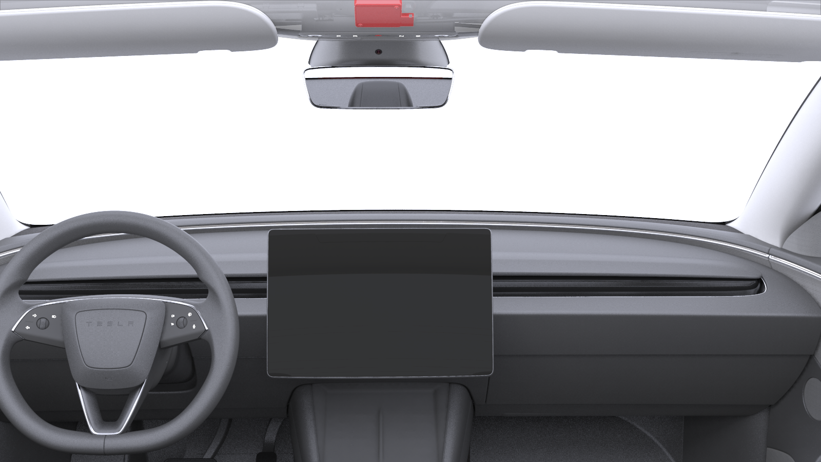
| Cabin Radar (Front Passenger Occupancy Classification) |
Cabin Radar (ICR), located behind the front overhead console, detects and classifies occupants in the front passenger seat. The ICR communicates with the right vehicle controller (VCRIGHT) via Vehicle Controller Area Network (VEH CAN) and sends data to the Autopilot ECU via CAN-FD for logging purposes. North American vehicles need to not only detect but classify a front passenger to remain compliant with homologation standards.
The ICR emits a radio frequency (RF) wave, which bounces off the surroundings and returns to the module. The ICR algorithm then converts the reflected signal's distance and velocity into object or human detection. This detection is based on the object's movement, size, and location.
Serviceabilitylink
Note
Avoid placing objects directly in front of the ICR, as this may obstruct occupant detection.
Tip
Vehicles with cabin radar hardware can be identified with the cfg_InteriorCabinRadarType vehicle configuration. Cabin Radar will have the TESLA configuration.
The North America Model Y does not always utilize ICR for front passenger classification, some vehicles will use the Occupant Classification System, explained further in the next session. The classification system being utilized can be determined from the following gateway configuration:
| System Type | cfg_OccupancyClassificationFeatureType |
|---|---|
| ICR | TESLA_CABIN_RADAR |
| OCS | DISCRETE_SENSOR_OR_NA |
Use VCLEFT_frontOccupancySwitch and VCFRONT_driverPresent to determine if an occupant was in the seat. These are the same signals are used for the resistive pad. When diagnosing issues of the system, use the following terminology:
- False Positive - There is no occupant in the seat, but the system is detecting an occupant.
- False Negative - The seat is occupied, but the system is not detecting an occupant.
A false positive can lead to the vehicle staying powered on with no occupants in the cabin. This could result in loss of range, as well as walk away lock not operating at expected. A false negative can lead to the vehicle not turning on when someone is in the cabin.
Occupant Classification System (North America Only)link
 |
|---|
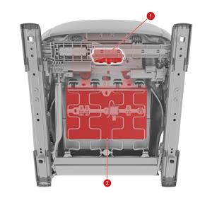
| 1. OCS Electronic Control Unit 2. Sandwich sensor (North America vehicles only) |
 |
|---|
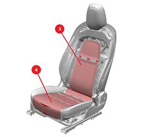
| 1. Seat-back pad 2. Seat-cushion pad |
The Occupant Classification System (OCS) comes in two different variants that can be deciphered via a CAN signal.
| System Type | OCS1P_noSandwichType |
|---|---|
| Sandwich-OCS | SANDWICH_INSTALLED |
| SBR-OCS | no_sandwich_na |
The Sandwich-OCS is made up of four individual components: the OCS Electronic Control Unit, the sandwich sensor, the seat-back pad, and the seat-cushion pad. The OCS monitors the seated weight plus conductive presence on the cushion and seat-back to estimate the type of occupant sitting in the front passenger seat, and communicates the status to the RCM using a CAN signal. The RCM uses this information to determine whether to enable or suppress the deployment of the front passenger airbag and if applicable, corresponding knee airbag. The OCS ECU sends a classification to the RCM where the passenger airbag light state is determined by the RCM's receipt of the OCS classification. The RCM transmits a signal to the MCU requesting the passenger airbag state light (PASS AIRBAG OFF/ON).
The SBR-OCS is made up of the same components as the Sandwich-OCS, except instead of the mutual capacitance "sandwich" sensor, a resistive pad or "SBR" is used.
If the OCS detects a non-qualified adult (which includes small children in/out of child restraints or empty seats), the front passenger front and knee airbag is disabled. The intent is to detect child booster or rear facing infant vehicle seat where even stage 1 deployment provides too much energy absorption for these types of occupant.
Note
Seat position, occupant size, and weight distribution affect the sensed values. An occupant whose weight is near the classification thresholds can cause the airbag deployment strategy to toggle between regions.
Serviceabilitylink
The Sandwich Occupant Classification System is calibrated for each individual seat at the factory. This makes the seat subcomponents non-serviceable. To service a front passenger seat, it must first be of SBR-OCS type.
The OCS measures the capacitance on the seat back and seat pad to determine the occupant contact area in the front passenger seat. The electronic control unit compares this capacitance change to the internally stored threshold to determine whether the seat is occupied, and what size of passenger is detected (see figure below). The OCS sends this information to the restraint control module to either disable the front passenger airbag and knee airbag. The occupant size determines if the active vent is used during higher energy collisions. The Active Vent will lower the pressure in the airbag when the occupant is smaller.
 |
|---|
| OCS Classification By OCS and Seat Track Position Sensor |
| Front Passenger Seat Occupancy | Passenger Airbag Indicator Center Display - North America | Passenger Airbag Stages |
|---|---|---|
| Seat empty, child seat, or small child | PASS AIRBAG OFF | None |
| Small occupant (~100 lbs) | PASS AIRBAG ON | 1st, 2nd and Active Vent |
| Large occupant (>160 lbs) | PASS AIRBAG ON | 1st and 2nd |
Occupancy Stages
The RCM notifies the occupants of the disable status by displaying the PASSENGER AIRBAG ON/OFF indicator in the MCU. If the MCU goes out with the drive rail on, the center display will display the status of the Passenger AirBag.
If a fault is detected, the OCS sends a message to the restraint control module. The RCM responds by sending a command message to the center display to display the Tesla Restraint System airbag indicator.
Calibration of the system when it is new is done using a Toolbox routine common to all platforms.
Resistive Padlink
 |
|---|
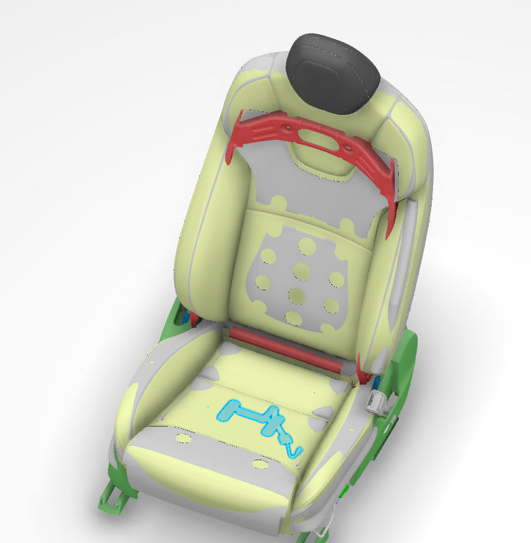
| Driver Occupancy Sensor |
This illustration is of the passenger Occupancy Sandwich Sensor. The driver Occupancy Sensor should look very similar to the rear passenger sensors
 |
|---|
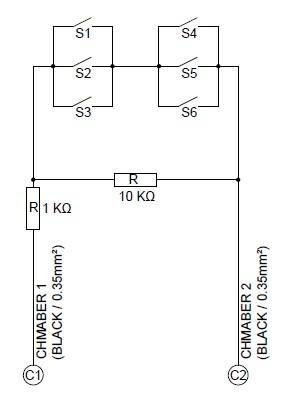
| Driver Occupancy Sensor - Circuit |
 |
|---|
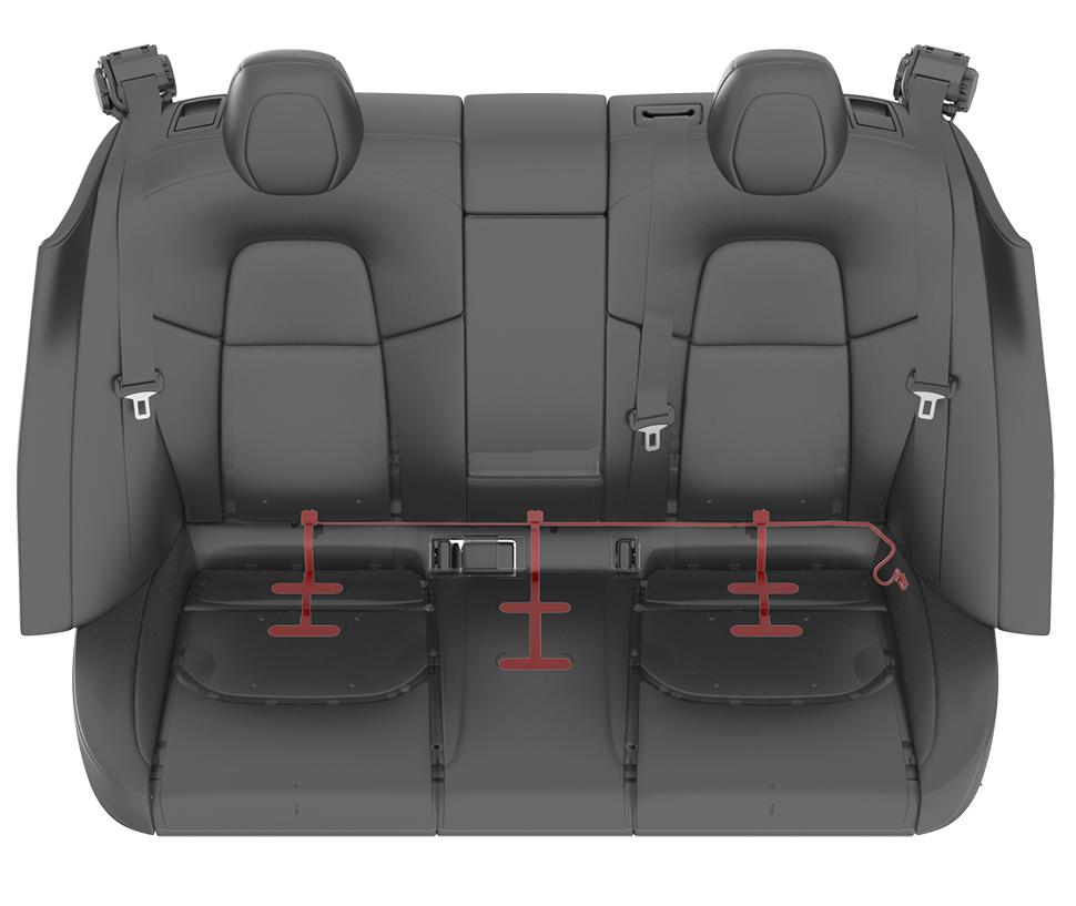
| Rear Passenger Occupancy Sensors |
 |
|---|
| Rear Passenger Occupancy Sensors - Circuit |
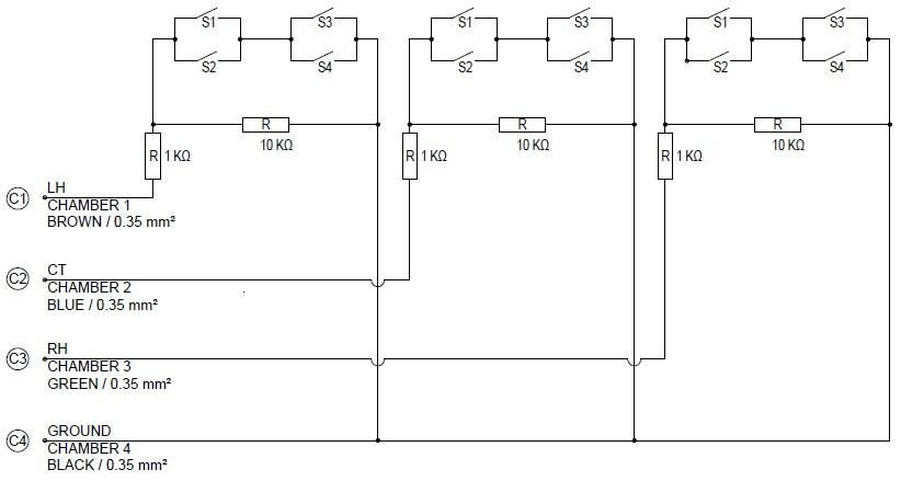
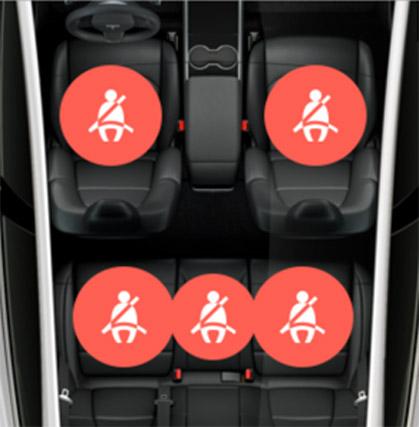
All seats contain occupancy sensors; resistive pads, with the exception of the front passenger seat in North America. The occupancy sensors are located in the seat cushions. The occupancy sensors are switches distributed throughout the cushion connected in both parallel and series. Having the sensors distributed throughout the cushion helps to prevent situations where small items might trigger the seat belt reminder indicator.
The first row driver and passenger seat belt telltales are combined together into a single indicator. This symbol is placed on the center display and is visible at all times. All seat belt telltales are displayed as an overhead view of all seats. For Model Y sold in Europe, there is an additional passenger airbag cutoff switch for the front passenger seat.
 |
|---|
| Telltale |
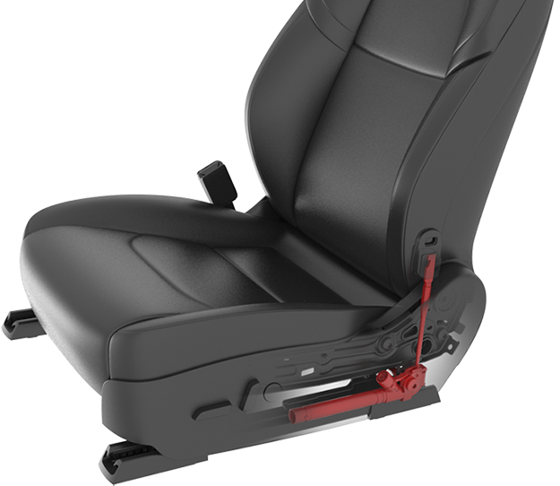
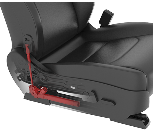
Seat Track Position Sensor (North America vehicles only)link
The seat position sensor (STPS) is used to determine the distance between the passenger seat and the front airbag. Information from the seat position sensor allows the RCM to disable stage 2 of the airbag if the seat is forward of a pre-determined point in seat track travel (closer to the airbag module). The seat position sensor is a Hall effect sensor, mounted on the outboard seat track of the passenger seat. The seat track includes a metal bracket that shunts the SPS magnetic circuit, creating two states of seat position. The shunted state represents a rearward seat position. The non-shunted state represents a forward position where metal is not present next to the sensor. These 2 states are inputs to the RCM.
When the seat position sensor informs the RCM that the state 1 threshold is reached (seat is rearward), the RCM does not disable stage 2. When the state 2 threshold is reached (seat is forward), the RCM disables stage 2 deployment of the driver airbag.
Note
Stage 2 deployment is also disabled if the RCM detects that the sensor is not operating as expected.
The sensor is attached to the seat track with a screw.
Impact Sensors and Door Pressure Sensorslink
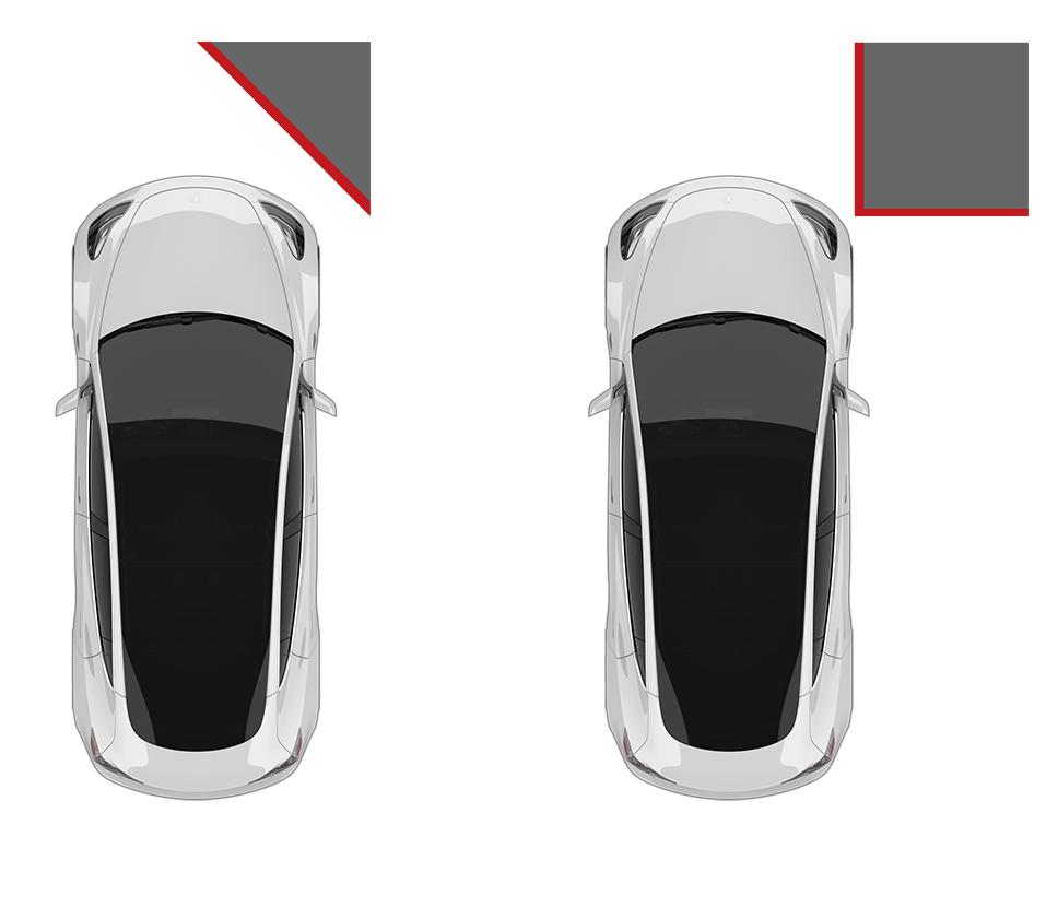
The Model Y uses 6 accelerometer type crash sensors containing a sensing device that monitors vehicle acceleration (positive and negative), and 4 pressure sensors, 2 inside the front doors and 2 inside the rear doors. The crash sensors send data to the RCM. The RCM uses the data from the sensors to determine if a collision is severe enough to warrant any airbag and/or seat belt pretensioner deployment. Data from the front LH and RH accelerometers are compared to determine if the impact contains offset or is angular.
 |
|---|
| Angled and Offset Impact |
 |
|---|
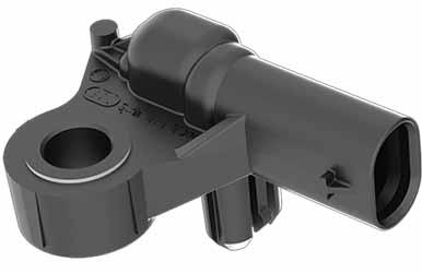
| Impact Sensor |
Front Sensorslink
 |
|---|
| Front Bumper Satellite Sensor Location |
The 2 front bumper sensors detect front and rear impacts.
 |
|---|
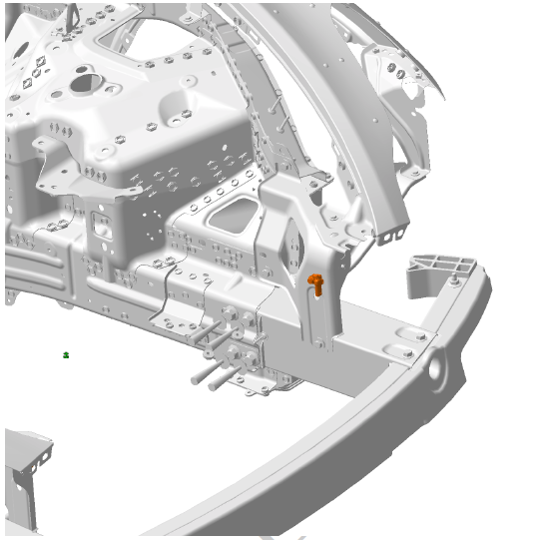
| Front End Module Bracket Satellite Sensor Location |
The 2 front end module bracket sensors detect front and rear impacts. These sensors sit higher up and further back than the front bumper sensors.
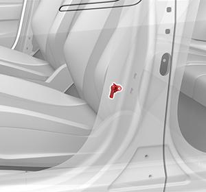
B-Pillar Sensorslink
 |
|---|
| B-Pillar Sensor Location |
The B-Pillar sensors detect side impacts.
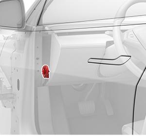
Door Pressure Sensorslink
 |
|---|
| Front Door Pressure Sensor Location |
|
|---|
| Rear Door Pressure Sensor Location |
 |
|---|
| Pressure Sensor |
The Piezo-electric pressure sensors mounted inside the front and rear doors measure the dynamic pressure change caused by deformation of the door caused by side impact. They require a sealed door compartment to work properly.
The inputs from the pressure sensors are processed by the restraint control module to deploy the side airbags and the seat belt pretensioners.
Warning
Always reinstall or replace any plug or tape removed from a door shell when servicing any component inside of the door. The pressure sensors are calibrated to respond to pressure changes within the door in the event of a side impact. Opening more holes in the door creates additional escape paths for air, which diminishes the sensor's ability to accurately detect a side impact, and can negatively affect airbag deployment.
Passenger Seat Position Sensorlink
 |
|---|
| Seat Track Position Sensor (North America vehicles only) |
The passenger seat position sensor measures seat position. The seat position sensor sends position data to the RCM to determine airbag deployment strategy. For vehicles equipped with a passenger knee airbag, if the passenger seat position sensor is in the forward position and the occupant is wearing a seat belt, the front knee airbag will not be deployed.
The sensor is secured to the seat track with one screw.
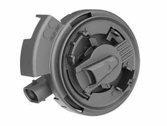
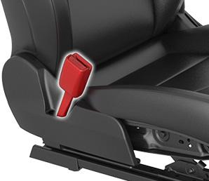
Seat Belt Buckle Switchlink
 |
|---|
Five seat belt buckle switches are fitted to determine the deployment strategy for lap and shoulder pretensioners, and load limiters. The front row seats each contain a shoulder pretensioner, lap pretensioner, and a load limiter. While the second row outboard seats only contain shoulder pretensioners. There aren't any additional seat belt restraints for the middle seat. For the front passenger seat, the seat belt buckle switch also determines the active vent deployment strategy for larger occupants.
Deployable Restraintslink
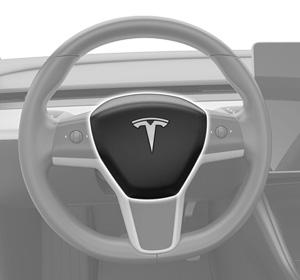
Driver Airbagslink
 |
|---|
| Driver Airbag |
 |
|---|
| Driver Knee Airbag (North America vehicles only) |
Mounted on the steering wheel, the driver airbag is a multi-stage front airbag that provides protection from impact with the steering wheel and the surrounding dashboard for adults of all sizes. During an impact the stiffness of the driver airbag is governed by the deployment strategy and is based on the severity of the crash. First stage only will be used for less severe frontal impacts and the second stage will deploy in more sever cases to ensure that the airbag is in position early.
A single stage driver knee airbag is located beneath the steering column in the lower part of the instrument panel. The knee airbag deploys any time the steering wheel airbag deploys. Occupant kinematics are greatly improved by the knee airbag in situations where the occupant is unbelted.
Front Passenger Airbagslink
 |
|---|
| 1. Front passenger airbag 2. Knee airbag (North America vehicles only) |
| Front Passenger Airbag and Knee Airbag |
The passenger front airbag is mounted behind the instrument panel on the front passenger side. The passenger airbag deploys through the top of the dashboard trim, and then wraps forward around the dashboard and glove box area. Similar to the driver airbag, the passenger front air bag is multi-stage. The passenger airbag provides protection for occupants based on their size as calculated by the Occupant Classification System (OCS). If the seat is empty, the occupant is determined to be below the weight threshold the airbag is suppressed. The airbag shape differs from the circular driver airbag in that it contains “lateral lobes” or "bullhorns" which are used to help control the lateral and rotational motion of the passenger’s head.
Multi-stage airbags with active vents allow for variable levels of energy absorption during an impact. Normal airbags deliver only one level of energy absorption and deflate. In a dual stage airbag the controller can activate a second stage after the first to provide additional energy absorption if it detects a more severe impact. In North America, Model Y front passenger airbags also are equipped with an active vent which when deployed will reduce the energy absorbed. The active vent would be used in the case of a smaller occupant to prevent excessive force on the occupant.
If equipped, the single stage passenger knee airbag is located inside the lower part of the instrument panel. Occupant kinematics are greatly improved by the knee airbag in situations where the occupant is unbelted. In all frontal cases, when a belted occupant is seated in the passenger seat, and the seat is forward of a pre-determined point in seat track travel (closer to the airbag module), the passenger knee airbag will not deploy. When the a belted occupant is seated in the passenger seat and the seat is behind the pre-determined point in seat travel (further away from the airbag module) the knee airbag will deploy.
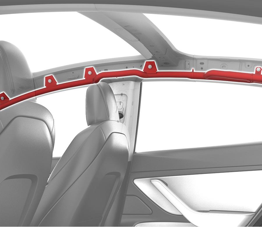
Curtain Airbaglink
 |
|---|
| Curtain Airbag |
The side curtain airbags are located under the headliner trim on the LH and RH sides of the vehicle. They inflate over the full area of the front and rear side windows to form a cushion, protecting the occupant’s head from contact with the window frame or pillar(s) in a side-impact collision. The side curtain airbag deploys downwards from the top and drapes over the entire glass area. The side curtain airbags stay inflated for a few seconds after a collision in case the vehicle rolls over.
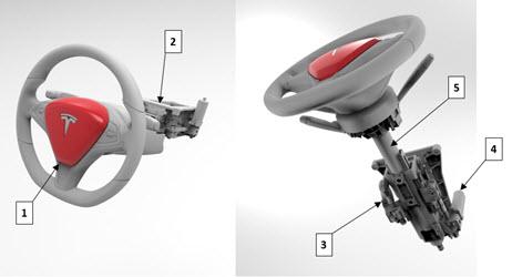
Steering Columnlink
 |
|---|
| 1. Driver Airbag 2. Steering column carrier 3. Tilt motor 4. Telescopic motor 5. Steering shaft |
The steering column is designed to absorb energy and collapse during frontal collisions, in order to decrease the chance of injury to the driver. The column has 100mm of collapsible travel. A deformable wire adds resistance to the collapsing motion. If the vehicle has been in a collision that caused driver airbag deployment, the column should be inspected to check whether it collapsed.
Warning
The steering column must be inspected whenever the driver airbag has deployed. Refer to BR-17-20-002, "Airbag Component Inspection and Replacement After Deployment, Model Y" for inspection instructions.
Seat Mounted Airbaglink
 |
|---|
| Seat Airbag, Left |
 |
|---|
| Seat Airbag, Right |
The side airbags are part of the front and second row seats. The seat side airbags are deployed from the outboard side of the seat, forming a cushion between the occupant and the door, protecting the occupant’s upper torso and pelvis area during a side impact.
Side seat airbags are built into the seat themselves, they are not serviceable. If deployed or damaged the seats will need to be replaced.
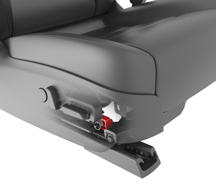
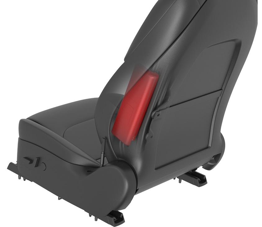
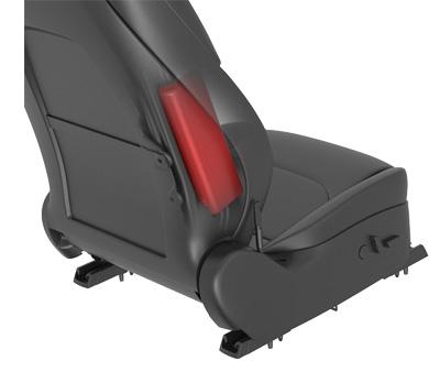
Far Side Airbag (Seat Inboard Side Airbag)link
 |
 |
|---|---|
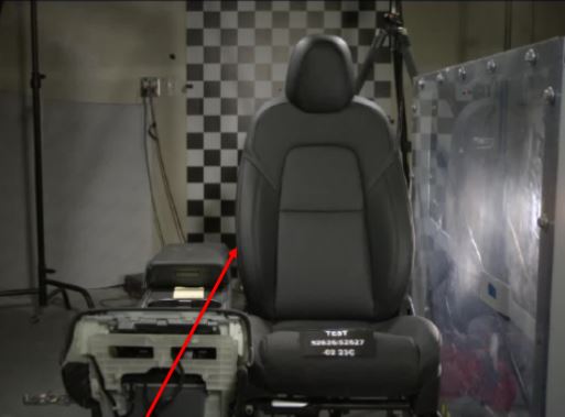
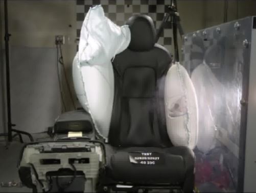
| Far side airbag location (red arrow) | Far side airbag (inboard) and Seat Mounted Airbag (outboard) after deployment |
Certain Model Ys have a driver seat far side airbag. A single stage airbag located on the inboard portion on the front driver seat. The far side airbag forms a cushing between the driver and passenger seat during a side impact.
Pretensionerslink
 |
|---|
| Lap Pretensioner, Left |
 |
|---|
| Lap Pretensioner, Right |
The driver and first row passenger seat belt pretensioners are a dual pretensioner system. The lap belt pretensioners are mounted on the seat, and the shoulder belt pretensioners are integral with the retractors. The outboard second row seats each have a single shoulder pretensioner. The initiators of all pretensioners are part of the seat belt pretensioner deployment loop and always deploy simultaneously.
Any time an airbag deployment occurs and the occupant is belted, the seat belt pretensioners are also deployed. These devices are designed to work together to safely absorb occupant energy. The pretensioners will not be deployed if the corresponding seat belt buckle is unlatched. If the signal is not available or faulted at the time of deployment The RCM assume seat belts are buckled and the pretensioners will be fired.
The RCM directs current through the deployment loops to the initiator to deploy pretensioners. Current passing through the initiator ignites the material in the canister, producing a rapid generation of gas. The gas produced from this reaction deploys the seat belt pretensioners, which remove slack in the lap and/or shoulder belts. The process is one time only and cannot be reversed. The component needs to be replaced after every deployment.
Load Limiterslink
Seat belts in the front row are equipped with a deployable load limiter, which tunes the amount of energy that the seat belts absorb from the occupant. To minimize the risk of occupant injury the load limiter selector can be deployed to decrease the maximum tension of the seat belts. When the load limiter selector is deployed the force absorbed by the seat belts decreases, which allows the airbags to absorb more occupant energy. The system is only deployed in frontal impacts where the airbags are deployed. In cases with only lateral motion or any rear impact, the seat belts absorb as much energy as possible. The load limiter is contained within the retractor housing.
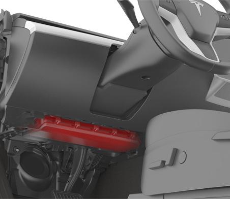
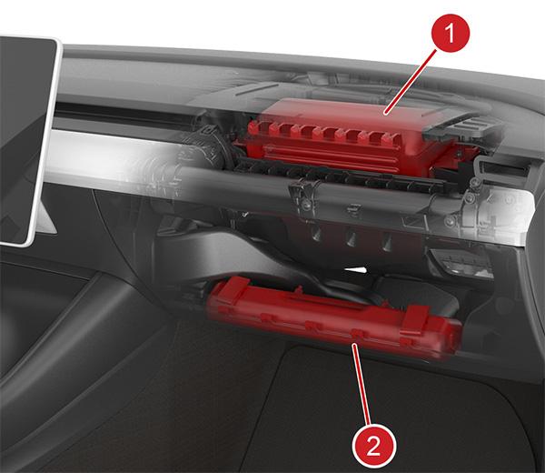
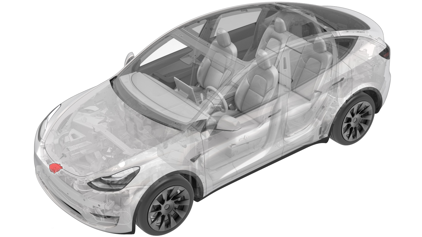
Pyrofuse Disconnectlink
A pyrofuse disconnect is installed inside the Model Y Ancillary Bay and joins module 2 and 3 of the HV battery. Specific HV battery events, such as over-current, overcharge, over-discharge, in addition to airbag deployment will result in the deployment of the pyrofuse disconnect . Refer to the High Voltage Battery section for additional information.
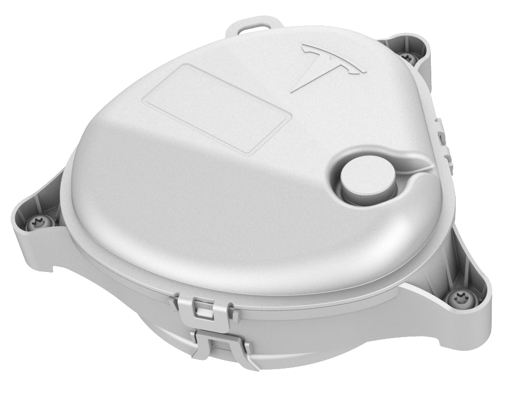
Pedestrian Warning Systemlink
 |
|---|
| Pedestrian Warning Speaker, location |
 |
|---|
| Pedestrian Warning Speaker, component |
Functionality and Purposelink
The Pedestrian Warning System (PWS) encompasses a speaker enclosed in a box at the right hand front of the vehicle, located on the front fascia. The PWS is a legal requirement based off region, the specifics of the requirement (pitch of noise, speed of vehicle etc) is dependent on which region the vehicle is located. Electric vehicles traveling at slow speeds must emit a noise to warn pedestrians of motion. As soon as a vehicle is put into gear the speaker emits a noise. Vehicles in the APAC market, not including Japan, have the ability to turn off the PWS.
Drive
The speaker emits a noise while the vehicle is in drive. As the vehicle accelerates, the noise goes up in pitch. Once the vehicle reaches a speed of 30kph/19mph the noise begins to fade out The forward motion noise sounds similar to a spinning fan and Tesla has taken precatuion to minimize the noise for customers inside the vehicle, the intent is that the Pedestrian Warning Speaker is only heard from outside the vehicle.
Reverse
When the vehicle is in reverse, the noise emitted by the PWS needs to be heard at the rear of the vehicle. Due to the fact that the speaker is located at the front of the vehicle, the noise for reverse is increased and can be heard within the vehicle. The sound while in reverse is more a tone. The noise in reverse intentionally sounds different than the noise in drive. No matter what the speed, the PWS will emit a noise while in reverse.
As of September 2020, the US requires all new electric vehicles be equipped with the Pedestrian Warning System.
Communication
The PWS receives messages via the UI. The drive inverter reports the gear and the speed of the vehicle to the gateway. The gateway then communicates this information to the UI where the audio system then transmits the appropriate noise based off these inputs. The audio system in the vehicle includes microphones, the amplifier that then communicates to all speakers. If there are issues with the Pedestrian Warning System, a good first debug step would be to check the other speakers in the vehicle to pinpoint if the issue is with the audio system as a whole or the Pedestrian Warning Speaker.