Low Voltage Controllers and Wiringlink
Last updated: October 20, 2023
Circuit and Connector Diagramslink
Circuit diagrams show the path of all circuits in the vehicle, and the connector reference shows the location and pin outs of all connectors in the vehicle.
Note
Connector references and circuit diagrams can be found on the Service website.
Low Voltage Architecturelink
Power Distributionlink
The Model 3 features both a low voltage system and a high voltage system. The following devices are connected to both the high voltage and low voltage systems:
- High Voltage Controller
- Power Conversion System (includes DC-DC)
- Drive Inverters (Front and Rear)
- HVAC Compressor
All other devices in the vehicle are powered solely by the low voltage system and the low voltage system features two independent sources of power:
- Power Conversion System (DC-DC)
- Low Voltage Battery (LV Battery)
The DC-DC receives power from the High Voltage Battery pack and converts it to low voltage power. Power from the DC-DC and low voltage battery are merged together inside the Front Vehicle Controller (VCFRONT). This controller is the “heart” of the low voltage power distribution system and all low voltage current flows through the VCFRONT before being distributed throughout the rest of the vehicle.
While the vehicle is "awake", the DC-DC converter is the primary source of low voltage power for the vehicle and the LV Battery is only discharged in the event of a DC-DC fault, or during peak loads for devices such as power steering, braking, or stability control systems. When the Model 3 goes to "sleep" the new sleep bypass will turn on and connect the entire low voltage system directly to the HV Battery to supply a continuous 10.6V rather than relying on just the LV Battery for power (this connection is capable of supplying up to 24V). If the LV Battery is drained during Sleep the DC-DC will still turn on and recharge it, and turn off again once recharged. E-Fuses control the flow of power to each device individually and can be "grouped" in firmware to create virtual power "rails" known as "Vehicle States".
Note
All Model 3 vehicles built in North America after January 1, 2020 use a Sleep bypass power supply.
High-level Vehicle States:
- Sleep
- Accessory
- Drive
- Conditioning
- Over the Air (OTA)
- Self-Test
Note
For more information on Vehicle States including a detailed list of the possible states, refer to the Vehicle Power States section of this document.
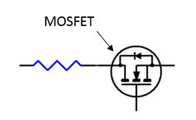
An E-Fuse is a transistor (MOSFET) and a current sensor. When the current through the transistor exceeds either the firmware or hardware limits, the switch opens rapidly.
Types Of E-Fuses:
- Discrete E-Fuse
- A MOSFET connected as a "high-side" switch with a pull-up resistor driven by an output pin, configured as an open-drain to deactivate downstream loads.
- Typical Applications:
- High-side driven devices which draw more than 25A.
- H-Bridge driven devices which draw more than 5A.
 |
|---|
| Discrete Style E-Fuse |
- Integrated Circuit (IC) E-Fuse
- A MOSFET connected as a "high-side" switch, but with a separate chip integrated into its package that includes special hardware (like a current sensor, temperature sensor, thermistor, etc.) to help characterize and determine when to deactivate downstream loads.
- Typical Applications:
- High-side driven devices which draw less than 25A.
- H-Bridge driven devices which draw less than 5A.
Note
For more information on E-Fuses, refer to the E-Fuses section of this document.
Powering and Controlling Connected Loadslink
Powering Loadslink
The low voltage controllers on the Model 3 use the following types of integrated circuits to control the flow of power to the various loads connected to the vehicle controllers. The integrated circuits are an H-Bridge and a High-Side Driver.
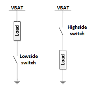
High-Side Driver:
A high-side driver (shown below) is a transistor switch that can turn power on and off to a downstream load. When the switch is ON, the battery voltage is applied to the load. The current that flows depends on the load. When the high-side driver is ON it does not affect the current. Many high-side drivers feature a current sense inside the switch, and turn off automatically in the event of an over-current. A high-side driver which turns off when a specific current level is reached is called an “E-Fuse”.
For more information on E-Fuses see: E-Fuses.
 |
|---|
| High-Side Driver vs. Low Side Driver |
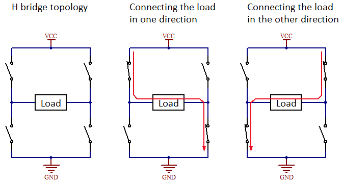
H-Bridge:
An H-bridge (shown below) is a circuit that can apply voltage across a load in two directions. It is commonly used for controlling DC brushed motors, since each direction of current flow will spin the motor in a different direction. Some examples of DC motors controlled in this way are motors in the seat, steering column, and window lift.
Note
When probing the pins for an H-bridge, make sure to measure across the two pins of the load. If only measuring from one of the H-bridge pins to ground, the readings may not match what the load is seeing.
 |
|---|
| H-Bridge |
Harnesses and Pass-throughslink
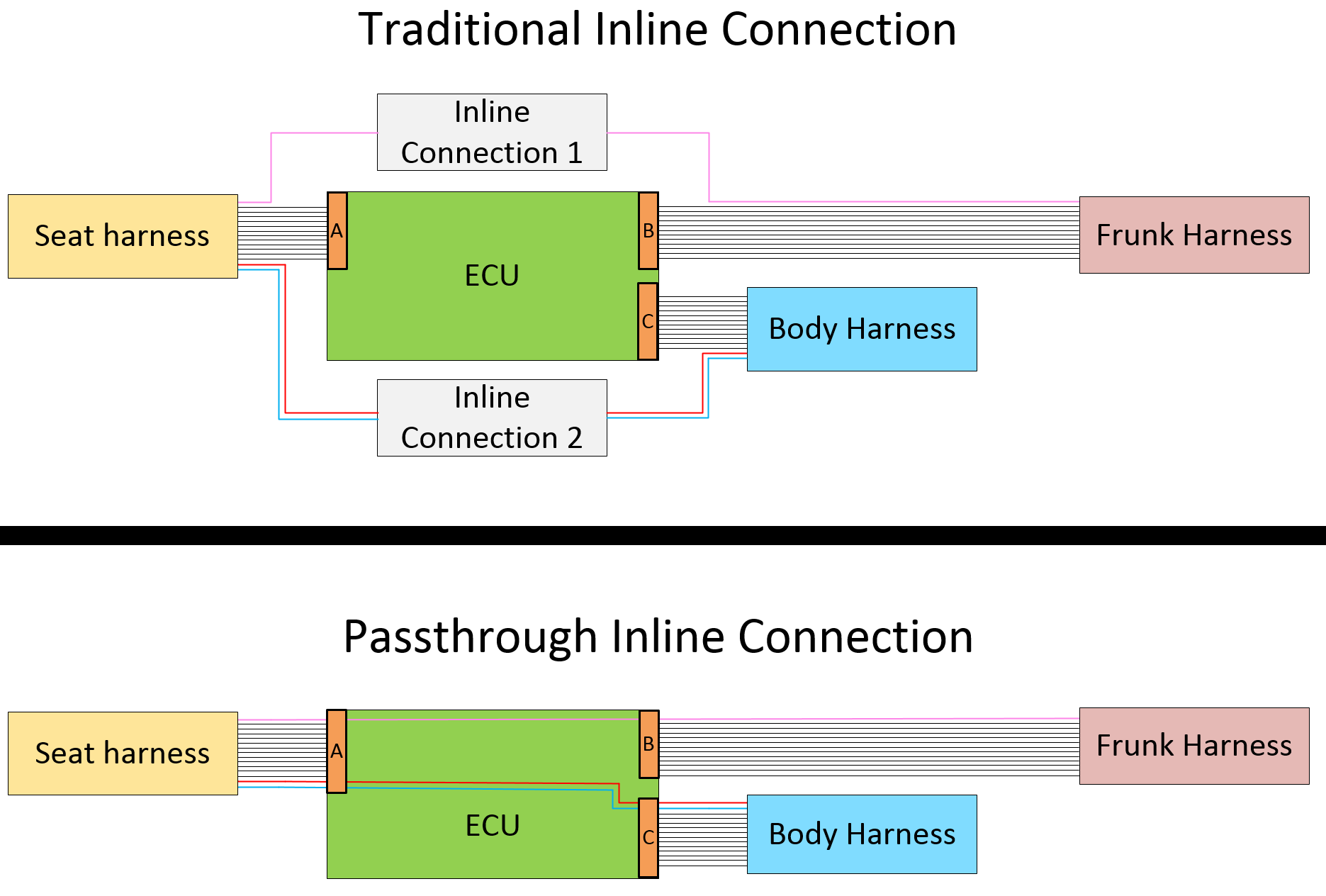
In addition to the use of traditional low voltage harnesses, the Model 3 also makes use of pass-through style connections to reduce the number of the inline connectors and wire splices required to connect the various controllers in the vehicle.
A pass-through style connection is just a metal trace on a printed circuit board (PCB) on one of the vehicle's low voltage controllers and acts like a wire harness extension. This trace does not touch any other circuitry on the PCB. It is just a "wire".
Example of a Pass-through vs. Traditional Inline Connector:
- By using traditional inline connectors the design requires connectors A, B, and C along with inline connectors 1 and 2.
- By using pass-throughs the design only requires connectors A, B, and C. Inline connectors 1 and 2 are not required.
 |
|---|
| Traditional Inline Connectors vs. Inline Connectors |
Cut-Loopslink
Power wires for the pack contactors and Restraint Control Module (RCM) are routed throughout the vehicle into two loops of wire. After a crash event, first responders (firefighters, EMTs, etc.) cut these wires to disconnect the HV Battery pack from the vehicle, and disable airbags. Sometimes using hydraulic rescue equipment ("jaws of life" in North America) can accidentally trigger air bag deployment, so de-energizing the airbag circuits eliminates the risk of accidental airbag deployment. First Responder Cut-Loops exist in both the front and rear of the vehicle. If one location is inaccessible (due to body deformation as a result of a crash), the other loop can be accessed instead.
 |
|---|
| First Responder Cut Loop, Front Location |
Controllerslink
Front Vehicle Controller (VCFRONT)link
 |
|---|
| Component Location |
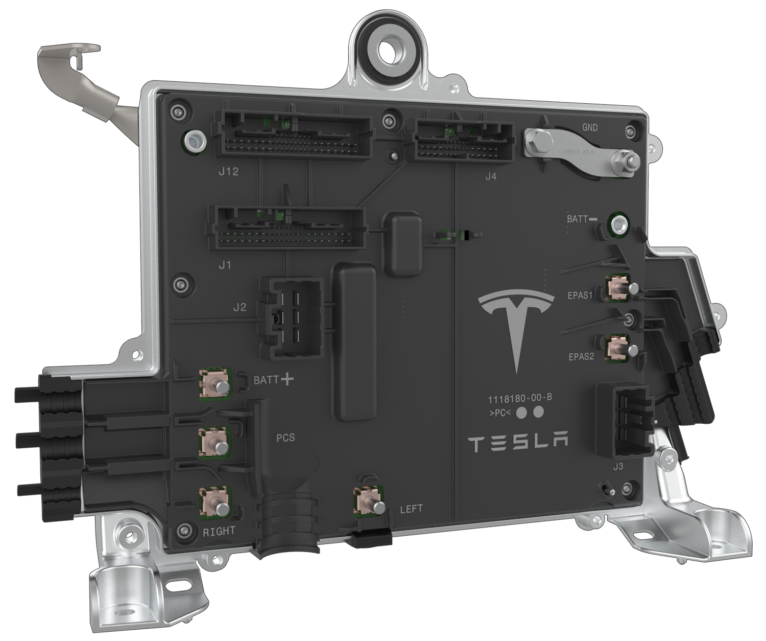 |
J1 X010High-Side Drive: Battery Backup Siren, Frunk LED, Homelink ECU, Windshield Upper Glass Heater, Windshield Washer Fluid Pump, Evaporator TXV Solenoid, Horn Low/High Tone, EPAS 1 Wake, Radar, Front Drive Inverter, Front Drive Inverter Discharge, MCU Audio, Front Drive Unit Oil Pump, Autopilot2Half-Bridge: Frunk Latch Primary Release/Reset, Frunk Latch Secondary Release/ResetPower In: Frunk Access PostDigital In: Windshield Washer Fluid Level, Frunk Emergency Release Switch (wake), Frunk Latch Open Switch (wake), EFuse LockoutDigital Out: Front To PCS EnableAnalog In: Brake Fluid Level SensorGround Return: Evaporator TXV Solenoid GNDLIN: Homelink ECU LIN, Windshield Wiper LIN, Li-Ion LV Battery LINCAN: Private CAN P/N (Termination 120ohm) |
J2 X011High-Side Drive: HCU ESP ABS Motor, Windshield Wiper PowerHalf-Bridge: Condenser Fan Phase A/B/CGround: Condenser Fan GND Shield |
J3 X012High-Side Drive: iBooster, MCU Logic, HCU ESP ABS Valve, Autopilot1 |
J4 X013High-Side Drive: Headlight Right/Left, Side Marker Right/Left, Fog Light Right/Left, Side Repeater Right/Left, iBooster Wake, EPAS 2 WakeHalf-Bridge: Active Louver Phase A/B/CAnalog In: Lead-Acid LV Battery Temp Sensor, Ambient Air TempGround Return: Batt Temp Sensor Return, Ambient Air Temp ReturnNot Connected: Active Louver GND ShieldLIN: Headlight Right LIN, Headlight Left LINCAN: Vehicle CAN P/N |
PCS X014High-Side Drive: PCS |
BATT+ X015Power In: LV Battery Positive |
RIGHT X016High-Side Drive: Right Controller (VCRIGHT) |
LEFT X017High-Side Drive: Left Controller (VCLEFT) |
GND X018Ground Chassis: GND Chassis |
EPAS1 X019High-Side Drive: EPAS 1 |
EPAS2 X020High-Side Drive: EPAS 2 |
J12 X021High-Side Drive: HV Compressor Controller LV PowerHalf-Bridge: 5-Way Coolant Valve A/B, HVAC Chiller EXV Phase A/B/C/D, Coolant Pump Battery Phase A/B/C, Coolant Pump Powertrain Phase A/B/CHall Sensor In: 5-Way Coolant Valve HallDigital Out: Coolant Level Conductive SensorAnalog In: Refrigerant Discharge Pressure/Temp, Refrigerant Suction Pressure/Temp, Coolant Temp 1 / 2Vref Output: Refrigerant Discharge 5V, Refrigerant Suction 5VGround Return: Refrigerant Discharge GND, Refrigerant Suction GND, 5-Way Coolant Valve Sensor GND, HVAC Compressor Controller LV GND, Coolant Temp 1 / 2 GND, Coolant Level Switch GNDGround: Battery Coolant Pump GND Shield, Powertrain Coolant Pump GND ShieldPass-through: Vehicle CAN P/N |
BATT- X022Power In: LV Battery Negative |
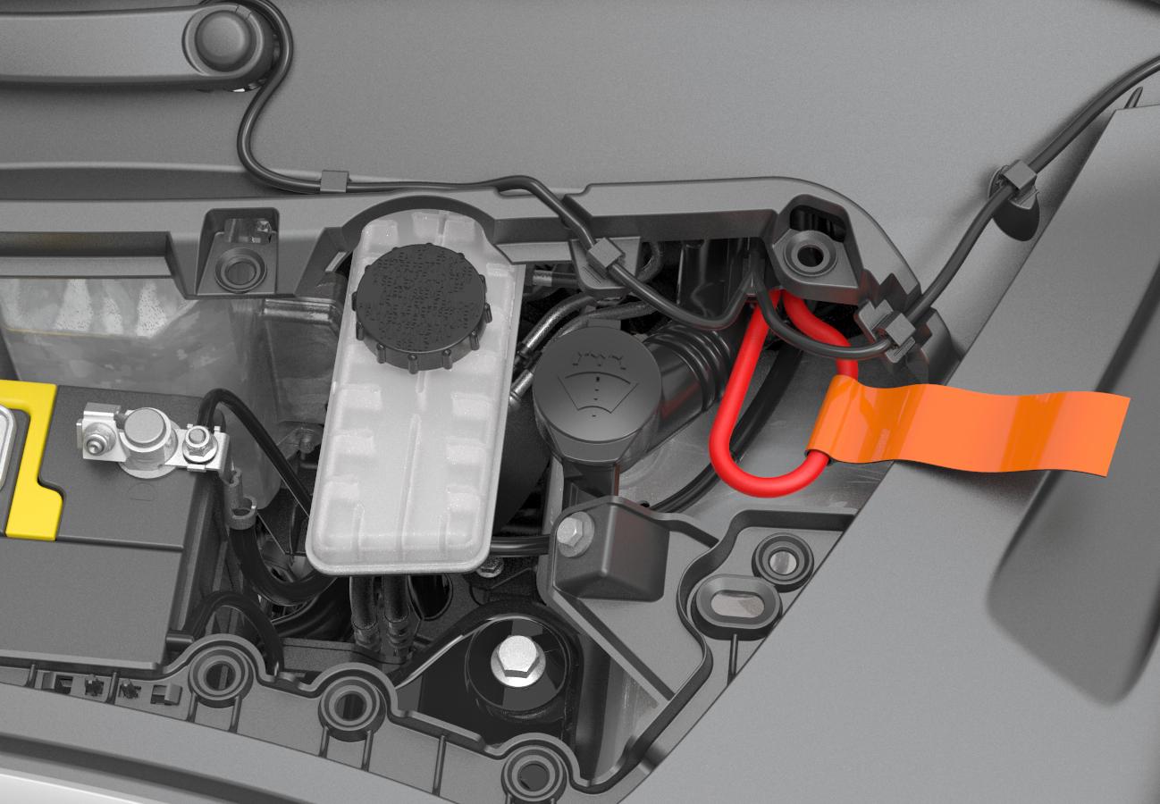
The Front Vehicle Controller is located in the front of the vehicle, under the hood, directly behind the LV Battery. The controller is powered by the LV Battery and the PCS (Power Conversion System), depending on Vehicle State. The front controller provides power delivery to the entire low voltage system, and manages everything under the hood. Information is relayed to devices by a combination of direct I/O, CAN, LIN, and pass-through connections. The front vehicle controller is an always on component, receiving power during sleep to provide wake inputs. It distributes power to other devices through a series of E-Fuse groupings. In the event of low voltage battery power loss, the front vehicle controller responds to a 9V to 12V source on the front access post to release the primary and secondary front trunk latches.
Note
Refer to the Service Manual for information about accessing jump posts.
Communicationlink
The front vehicle controller supports both CAN and LIN communication. The controller is connected to, and communicates on, both the vehicle (VEH) and private (PTY or party) CAN busses. Commands from VCFRONT that are consumed by Electronic Control Units (ECUs) on the chassis (CH) CAN bus are forwarded by the Gateway (GTW). The front vehicle controller is software-configurable to serve as the forward CAN termination point for the Private Bus in Rear Wheel Drive (RWD) vehicles. In Dual Motor vehicles, the front drive unit terminates the bus. This has implications when measuring the bus resistance, as the controller does not terminate the bus during Sleep or when not powered. Refer to the Communication Architecture section for important information on CAN bus termination strategies.
The front vehicle controller communicates with the right headlight ECU and HomeLink module on LIN 1, and the left headlight ECU and the wiper module on LIN 2.
Functionslink
The front vehicle controller is responsible for these vehicle functions:
- Primary I/O Functions
- Intelligent Battery Sensor (IBS)
- Tesla Air Suspension (TAS)
- Thermal Management
- Condenser Fan
- Battery Pump
- Powertrain Pump
- Active Shutters
- 5-Way Valve
- Chiller and Electronic Expansion Valve (EXV)
- Thermal Expansion Valve (TXV)
- A/C Compressor
- Wiper System
- Wiper heating (windshield grid)
- Camera heating grid
- Front trunk latch
- Headlights (LIN)
- Fascia Lights (Fog and Marker)
- Front Drive Unit oil pump
- Horn tones (high and low)
- Secondary Functions (Power Delivery)
- Left Vehicle Controller (VCLEFT)
- Right Controller
- MCU Logic
- MCU Audio
- Autopilot 1 and 2
- Power Steering (EPAS) 1 and 2
- Electronic Stability Program (ESP) Hydraulic Control Unit
- Electromechanical Brake Booster (iBooster)
- Front Bluetooth Low Energy (BLE) endpoint
- Battery Backup Siren (BBS)
- HomeLink
- Radar Assembly
- Front Drive Inverter and Resolver
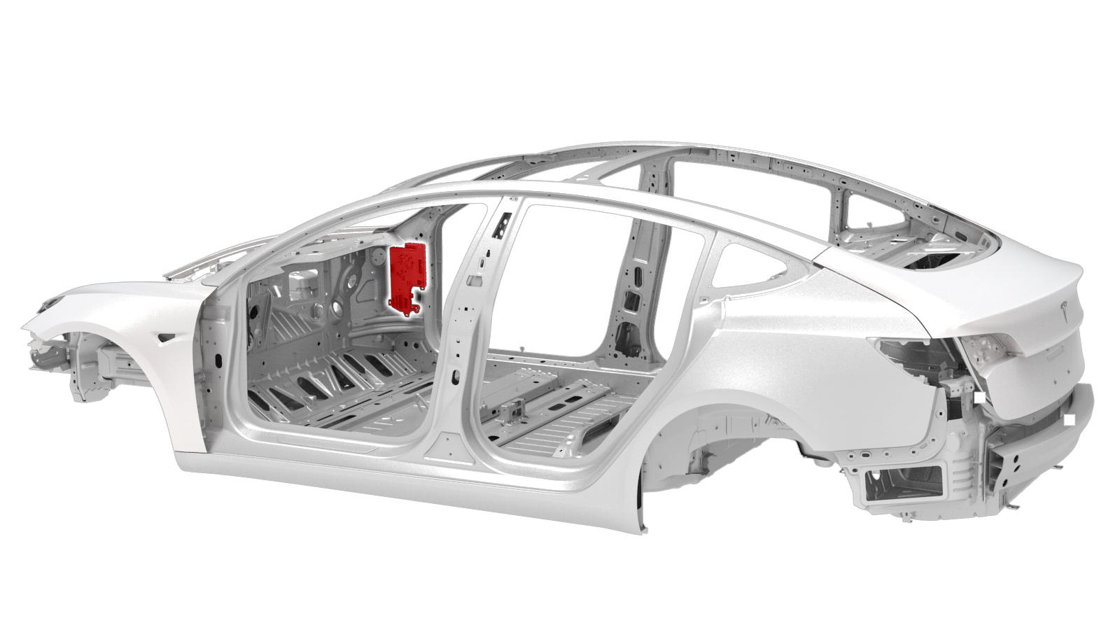
Left Vehicle Controller (VCLEFT)link
 |
|---|
| Component Location |
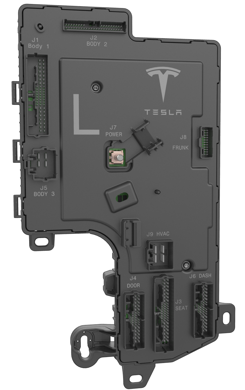 |
J1 Body 1 X030High-Side Drive: Body Side Brake Light, Body Side Tail Light, Body Side Turn Signal, Trunk Interior LED, Charge Port ECU, Seat Rear Left Heat Pad Backrest, USB Ports Front, LV Power Socket, Security Controller, Rear Drive Inverter, Headliner Power, Door Rear Map Pocket LED, BLE Rear, BLE B PillarHalf-Bridge: Parking Brake Apply/Release, Door Rear Latch Release/Reset, Window Rear Motor Up/DownHall Sensor In: Window Rear Hall A/BGround Return: Headliner Shared Ground Return, Seat Rear Shared Ground Return, LV Power Socket Ground Return, Headliner Shared Ground Return, Door Rear Shared Ground ReturnCAN: Private CAN P/NPass-through: Audio Speaker Front Door Pass-through P/N, Seat Side Airbag Pass-through P/N, Curtain Airbag Pass-through P/N, Lap Pretensioner Pass-through P/N |
J2 BODY 2 X031High-Side Drive: TPMS, Center Console Bin Front/Rear Switch LED, Rear Drive Inverter Discharge, Door Rear Window Switch LED, Door Rear Interior Handle Switch LED, Door Rear Exterior Handle Sensor 5vDigital In: Door Rear Latch Endstop Switch, Door Rear Latch Open Puddle LED (wake), Brake Switch Normally Open (wake)PWM In: Door Rear Exterior Handle Sensor (wake)Analog In: Seat Rear Left/Center/Right Occupancy Sensor, Seat Rear Left Buckle Sensor, Window Switch Rear, Door Rear Interior Handle Switch (wake)Vref Output: Ride Height Sensor RL 5VLIN: Headliner LIN, Trailer Light ECU LINPass-through: Battery Siren Private LIN Pass-through, Chassis CAN Pass-through P/N |
J3 SEAT X032High-Side Drive: Occupant Classification ECU, Seat Front Heat Pad Backrest/Cushion, Lumbar ECUHalf-Bridge: Seat Front Backrest Up/Down, Seat Front Track Forward/Reverse, Seat Front Lift Up/Down, Seat Front Tilt Up/DownHall Sensor In: Seat Front Backrest Hall, Seat Front Track Hall, Seat Front Lift Hall, Seat Front Tilt HallAnalog In: Seat Front Lumbar Switch, Seat Front Track Backrest Switch, Seat Front Buckle Sensor, Seat Driver Occupancy Sensor, Seat Front Lift Switch, Seat Front Thermistor CushionGround Return: Heat Pad Backrest/Cushion Ground Return, Seat Front Shared Ground Return, Occupant Classification ECU Ground ReturnLIN: Lumbar ECU LINPass-through: Chassis CAN Pass-through P/N, Seat Side Airbag Pass-through P/N, Lap Pretensioner Pass-through P/N |
J4 DOOR X033High-Side Drive: Door Front Window Switch LED, Door Front Interior Handle Switch LED, Door Front Exterior Handle Sensor 5v, Mirror Heat, Door Front Map Pocket LEDHalf-Bridge: Door Front Latch Release/Reset, Window Front Motor Up/Down, Mirror Tilt Left Right, Mirror Tilt Common, Mirror Tilt Up Down, Mirror Fold/UnfoldHall Sensor In: Window Front Hall A/BPWM In: Door Front Exterior Handle Sensor (wake)Digital In: Door Front Latch Open Puddle LED (wake), Door Front Latch Endstop SwitchVref Output: Mirror Dim, Mirror Tilt Position 5VAnalog In: Window Switchpack FL/FR/RL/RR, Door Front Interior Handle Switch (wake), Mirror Tilt Position Left Right, Mirror Tilt Position Up DownGround Return: Window Front Hall Ground Return, Shared Door Ground ReturnPass-through: Audio Speaker Front Door Pass-through P/N, Front Door Pressure Sensor Pass-through P/N |
J5 BODY 3 X034High-Side Drive: Trailer Light ECUGround-Chassis: Left Controller Ground Chassis |
J6 DASH X035High-Side Drive: Footwell LED Front, Accessory Feed 1 / 2, Accessory Feed - Always On, Steering Angle and Stalk ECU, Steering Wheel Controls ECUHalf-Bridge: Steering Column Motor Up/Down/In/OutHall Sensor In: Steering Column Up Down Hall, Steering Column In Out HallGround Return: Dashboard Harness Ground Return, Steering Column Tilt Hall Ground Return, Steering Column Tele Hall Ground ReturnLIN: OBD LIN, Steering Wheel Controls ECU LINCAN: OBD CAN P/N, Vehicle CAN P/NPass-through: Curtain Airbag Pass-through P/N, Seat Track Position Sensor Ground Pass-through, Seat Track Position Sensor Pass-through, Front Door Pressure Sensor Pass-through P/N |
J7 POWER X036Power In: Power |
J8 FRUNK X037High-Side Drive: Restraint Control ModuleVref Output: Ride Height Sensor FL 5VCAN: Vehicle CAN P/N (Termination 120ohm)Pass-through: Battery Siren Private LIN Pass-through, Chassis CAN Pass-through P/N |
J9 HVAC X038Half-Bridge: HVAC Blower Motor Phase A/B/CGround Return: HVAC Blower Motor Ground Shield |
| Left Vehicle Controller |
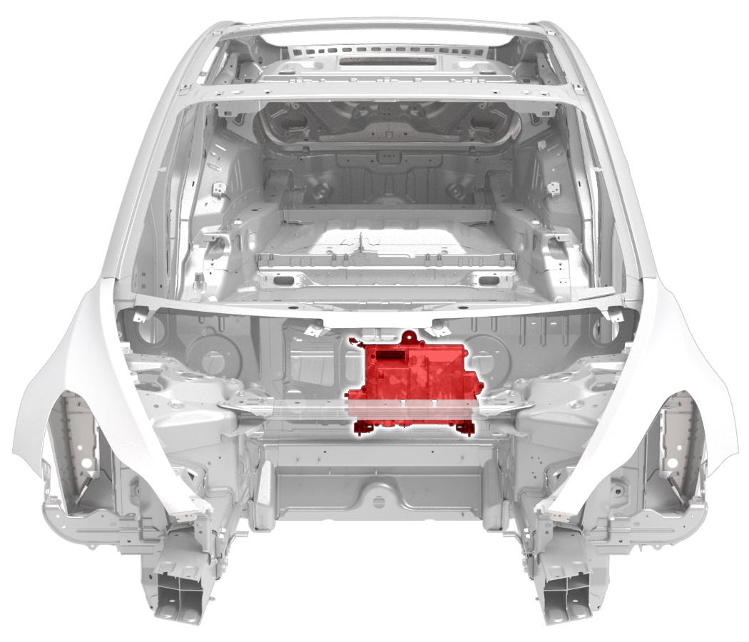
The left vehicle controller is located of the left hand side of the vehicle, regardless of market, behind the A-Pillar trim. The Front Vehicle Controller provides power to the controller, depending on Vehicle State, via a dedicated high current E-Fuse or standby shared E-Fuse. The controller manages the majority of devices on the left hand side of the vehicle via multiple internal microcontrollers. Information is relayed to devices by a combination of direct I/O, CAN, LIN, and pass-through connections. The LH controller is a component that is always on, receiving power during Sleep to provide wake inputs. It distributes power to other devices through a series of E-Fuse groupings.
Communicationlink
The LH controller supports both CAN and LIN communication. The main microcontroller and Electronic Park Brake (EPB) microcontroller communicate on both Vehicle and Private CAN. They are distinct devices even though they are on the same PCBA. The LH controller communicates with the steering wheel ECU, headliner ECU, Lumbar ECU, and Trailer ECU via LIN. Items such as the switchpack and door handles are direct I/O to the controller instead.
Functionslink
The left vehicle controller is responsible for these vehicle functions:
- Primary I/O Functions
- LH door (front & rear) functions
- Latch
- Exterior Door Handles
- Window Regulator
- Exterior Mirrors
- LH front seat functions
- Seat Controls
- Lumbar Support System (LIN)
- Heat
- Occupant Classification System (OCS)
- Seat Belt Buckle Switch
- Partial LH rear seat function (refer to Behavior and
Operation of the Seats Theory of Operation for more information)
- All occupancy sensors
- Buckle LH
- Heat LH
- Steering Column
- All LH interior lights
- Rear body-side exterior light
- LH Parking Brake
- Ride Height Sensors
- Brake Pedal Switch
- HVAC Blower (D4 controllers have an updated CBC Blower Controller)
- Center console LEDs
- LH door (front & rear) functions
- Secondary Functions (Power Delivery)
- Security Controller (VCSEC)
- Steering Wheel Controller (SWC)
- Steering Angle and Stalk ECU (SCCM)
- Restraint Control Module - RCM power (primary)
- LH B-Pillar BLE/NFC ECU
- Charge port ECU
- Trailer light ECU
- Headliner power
- Rear BLE ECU
- TPMS ECU
- Rear Drive Inverter and Resolver
- Low Voltage (LV) power sockets
- USB ports
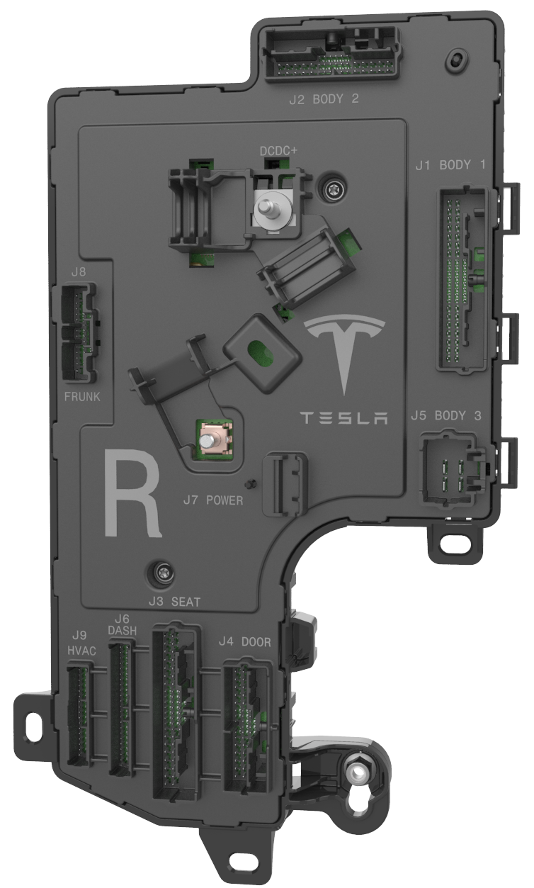
Right Vehicle Controller (VCRIGHT)link
 |
|---|
| Component Location |
 |
| J1 BODY 1 - X050 |
High-Side Drive: CHMSL Brake Light, Turn Signal, Body Side Brake Light, Body Side Tail Light, Exterior Trunk Light Left/Right, Trunk Interior LED, Oil Pump Rear Drive Unit, Trunk Latch Release, Seat Rear Left Heat Pad Cushion, Seat Rear Right Heat Pad Backrest/Cushion, Seat Rear Center Heat Pad Cushion, Radio Tuner, HV Controller, Exterior Trunk Tail and License Plate Lights, Door Rear Map Pocket LED, BLE B PillarHalf-Bridge: Parking Brake Apply/Release, Door Rear Latch Release/Reset, Window Rear Motor Up/DownHall Sensor In: Window Rear Hall A/BVref Output: Mirror Rear View DimGround Return: Seat Rear Shared Ground Return, Mirror Rear View Ground Return, Door Rear Shared Ground ReturnCAN: Private CAN P/N (Termination 720ohm)Pass-through: Left/Right Dashboard speaker Pass-through P/N, Audio Speaker Front Door Pass-through P/N, Restraint Control Module Pass-through 2, Curtain Airbag Pass-through P/N, Seat Side Airbag Pass-through P/N, Lap Pretensioner Pass-through P/N |
J2 BODY 2 - X051High-Side Drive: Light and Humidity Sensor, Door Rear Window Switch LED, Door Rear Interior Handle Switch LED, Door Rear Exterior Handle Sensor 5v, Ultrasonic Sensors RearPWM In: Door Rear Exterior Handle Sensor (wake)Digital In: Trunk Latch Open Switch (wake), Door Rear Latch Endstop Switch, Door Rear Latch Open Puddle LED (wake)Analog In: Seat Rear Right/Center Buckle Sensor, Seat Rear Left/Center/Right Heat Pad Cushion Temp, Trunk Exterior Switch (wake), Window Switch Rear, Door Rear Interior Handle Switch (wake)Ground-Chassis: Light and Humidity Sensor Ground ReturnGround Return: Ultrasonic Sensors Rear Ground ReturnLIN: Light and Humidity Sensor LIN, Ultrasonic Sensor 7 / 8 / 9 / 10 / 11 / 12 LINCAN: Chassis CAN P/N, Vehicle CAN P/N (Termination 720ohm)Pass-through: Center Dashboard Speaker Pass-through P/N, Restraint Control Module Pass-through 1, PCS Lockout Pass-through |
J3 SEAT - X052High-Side Drive: Occupant Classification ECU, Lumbar ECUHalf-Bridge: Seat Front Track Forward/Reverse, Seat Front Backrest Up/Down, Seat Front Tilt Up/Down, Seat Front Lift Up/Down, Seat Front Heat Pad Cushion/BackrestHall Sensor In: Seat Front Backrest Hall, Seat Front Track Hall, Seat Front Lift Hall, Seat Front Tilt HallAnalog In: Seat Front Track Backrest Switch, Seat Front Lift Switch, Seat Front Lumbar Switch, Seat Driver Occupancy Sensor, Seat Front Buckle Sensor, Seat Front Thermistor CushionGround Return: Heat Pad Backrest/Cushion Ground Return, Seat Front Shared Ground ReturnLIN: Lumbar ECU LINCAN: Chassis CAN P/NPass-through: Seat Side Airbag Pass-through P/N, Seat Track Position Sensor Pass-through, Seat Track Position Sensor Ground Pass-through, Lap Pretensioner Pass-through P/N, Occupancy Classification ECU Ground Return |
J4 DOOR - X053High-Side Drive: Door Front Window Switch LED, Door Front Interior Handle Switch LED, Mirror Heat, Door Front Map Pocket LEDHalf-Bridge: Window Front Motor Up/Down, Door Front Latch Release/Reset, Mirror Tilt Left Right, Mirror Tilt Common, Mirror Tilt Up Down, Mirror Fold/UnfoldHall Sensor In: Window Front Hall A/BPWM In: Door Front Exterior Handle Sensor (wake)Digital In: Door Front Latch Open Puddle LED (wake), Door Front Latch Endstop SwitchVref Output: Door Front Exterior Handle Sensor 5v, Mirror Tilt Position 5V, Mirror DimAnalog In: Window Switchpack FL/FR/RL/RR, Door Front Interior Handle Switch (wake), Mirror Tilt Position Up Down, Mirror Tilt Position Left RightGround Return: Window Front Hall Ground Return, Shared Door Ground ReturnPass-through: Audio Speaker Front Door Pass-through P/N, Front Door Pressure Sensor Pass-through P/N |
J5 BODY 3 - X054High-Side Drive: Premium Amp ECU, Rear Glass DefrostGround-Chassis: Right Controller Ground Chassis |
J6 DASH - X055High-Side Drive: Footwell LED Front, Glove Box LED, Glove Box Latch Release, HVAC PTC HeaterHalf-Bridge: HVAC Left/Right Vane Duct Open/CloseVref Output: HVAC Left/Right Vane Position 5vAnalog In: HVAC Left/Right Vane Duct Position, HVAC Cabin Temp 1 / 2 / 3Ground Return: HVAC Left/Right Vane Position Ground Return, Shared HVAC Ground Return, Glove Box Latch ReturnCAN: Vehicle CAN P/NPass-through: Left/Center/Right Dashboard Speaker Pass-through P/N, Restraint Control Module Pass-through 1 / 2, eCall Pass-through, Curtain Airbag Pass-through P/N, Seat Track Position Sensor Pass-through, Seat Track Position Sensor Ground Pass-through, Front Door Pressure Sensor Pass-through P/N |
J7 POWER - X056Power In: Power |
J8 FRUNK - X057High-Side Drive: HV Contactors, Restraint Control Module, Ultrasonic Sensors FrontDigital Out: Front EFuse LockoutGround Return: Ultrasonic Sensors Front Ground ReturnLIN: Ultrasonic Sensor 1 / 2 / 3 / 4 / 5 / 6 LINCAN: Chassis CAN P/N, Vehicle CAN P/N, Autopilot CAN P/N (Termination - Park ECU)Pass-through: eCall Pass-through, PCS Lockout Pass-through |
J9 HVAC - X058Half-Bridge: HVAC Lower/Upper Mode CW/CCW, HVAC Left/Right Bleed CW/CCW, HVAC Intake CW/CCWVref Output: HVAC Shared 5VAnalog In: HVAC Lower/Upper Mode Duct Position, HVAC Left/Right Bleed Duct Position, HVAC Intake Duct Position, HVAC Left/Right Vent Duct Temp, HVAC Evaporator TempGround Return: HVAC Shared Ground Return |
| DC-DC+ - No Reference found |
| RH Body Controller |
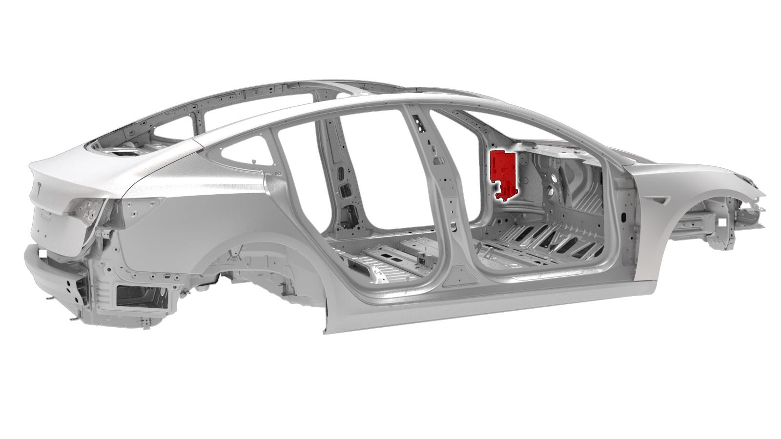
The right vehicle controller is located on the right hand side of the vehicle, regardless of market, behind the A-Pillar trim inside the IP Cockpit. The Front Vehicle Controller provides power to the controller, depending on Vehicle State, via a high power dedicated E-Fuse or standby shared E-Fuse. The controller manages the majority of devices on the right hand side of the vehicle via multiple internal microcontrollers. Information is relayed to devices by a combination of direct I/O, CAN, LIN, and pass-through connections. The RH controller is an always on component, receiving power during sleep to provide wake inputs. It distributes power to other devices through a series of E-Fuse groupings
Communicationlink
The RH controller supports both CAN and LIN communication. The main microcontroller, and EPB microcontroller communicate on both Vehicle and Private CAN. The Ultrasonic microcontroller communicates on the Chassis and AutoPilot CAN. The microcontrollers are distinct devices even though they are on the same PCBA. The RH controller communicates with the Lumbar and Light/Humidity ECUs via LIN. Items such as the switchpack and door handles are direct I/O to the controller.
Functionslink
- Primary I/O Functions
- RH door (front & rear) functions
- Latch
- Exterior Door Handles
- Window Regulator
- Exterior Mirrors
- RH front seat functions
- Seat Controls
- Lumbar Support System (LIN)
- Heat
- Occupant Classification System (OCS)
- Seat Belt Buckle Switch
- Partial RH rear seat function (refer to Behavior and Operation of the Seats Theory of Operation for more information)
- Buckles - RH and Middle
- Heat - Cushion (all)
- Heat - Backrest (RH)
- HVAC - Ducts & Temperature
- RH Body-side exterior lights
- Trunk exterior lights
- RH Interior lights
- CHMSL light
- RH parking brake
- Trunk latch
- RV mirror dimming
- Glove box
- Rear defrost
- Ultrasonic ECU
- RH door (front & rear) functions
- Secondary Functions (Power Delivery)
- RH B-Pillar BLE/NFC
- Restraint control module - RCM (secondary)
- Occupant Classification - OCS (LHD)
- Rear Drive Unit Oil Pump
- HV Controller
- HV Contactors
- Radio Tuner
- Light and Humidity Sensor
- Premium Amplifier
- PTC Heater
E-Fuselink
Overviewlink
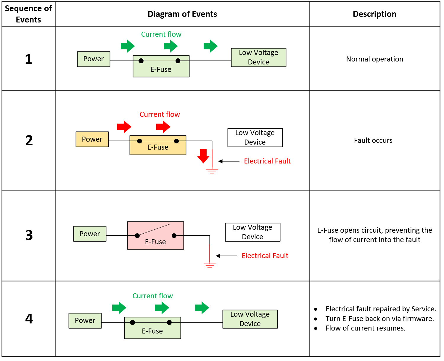
An electronic fuse (E-Fuse) is an electric switch without any moving parts, paired with protection circuitry. The E-Fuse replaces the relay and fuse combination that has existed in the automotive industry for decades. The change in technology enables better handling of electrical faults, and protects the electrical harness if a fault does occur. In the event of an electrical fault, an E-Fuse can interrupt current flow in milliseconds. For traditional fuses, during electrical faults, large currents can take several seconds to open, which might result in the vehicle's LV Battery voltage dropping low enough to disable critical systems and result in permanent damage to the electrical harness.
E-Fuses are a solid state switch, or a transistor and a current sensor. When the current through the transistor exceeds firmware or hardware limits, the switch opens rapidly. In order to use E-Fuses, detailed electrical behavior for each load is required in order to differentiate between a false positive and a true fault. This technology also enables advancements in on-board diagnostics, as the controller will be able to provide information on the state of health of an E-Fuse circuit. E-Fuse technology also significantly impacts the concept of traditional power "rails. The Model 3 groups individual E-Fuses into virtual rails called Vehicle States. E-Fuses allow the vehicle to turn devices off when not in use, instead of the device moving to a low power state.
Operationlink
An E-Fuse functions like a traditional fuse (opens circuit when too much current is flowing through it), except it reacts faster.
 |
|---|
| E-Fuse Overview |
Trippinglink
If an E-Fuse trips, a fault signal will be read by the microcontroller. Depending on the type of load the E-Fuse supplies, the construction of the E-Fuse, and the Vehicle State of when the fault occurs, the behavior may be to enter either auto-retry or latch-off mode. Some E-Fuses may only latch-off, some always auto-retry, and some are configurable. In Tesla applications, most fall under the configurable category.
Auto Retrylink
When an E-Fuse capable and configured for auto-retry trips, it will turn off, wait a period of time, then attempt to turn back on for a period of time. As long as an electrical fault is still present, this will repeat indefinitely at a low duty cycle (ratio to ON time versus OFF time), unless Tesla firmware intervenes.
The intent of this design is to have Tesla firmware intervene, using the fault signal sent to the microcontroller to immediately disable the E-Fuse and halt the auto-retry cycle until the conditions are correct to re-enable the E-Fuse.
Latch-offlink
When a latch-off E-Fuse trips, it turns off and remains off until firmware resets the E-Fuse. An E-Fuse reset is typically achieved by toggling the enable signal on and off. The enable always resets when there is a reset of the microcontroller, unless the enable line is locked out.
After an E-Fuse trips, Tesla firmware does not immediately try to re-enable the E-Fuse. The intent of this design is for the E-fuse to only trip when an electrical fault occurs, thus the E-Fuse should only be re-enabled after the electrical fault has been repaired by Service. A few exceptions to this statement exist:
- Capacitive inrush problems
- In this scenario, firmware quickly re-enables E-Fuses to precharge downstream capacitive loads.
- User accessible ports such as the LV power socket, USB ports, and the trailer light ECU can be reset by cycling control to those outputs to recover them.
Lock-Outlink
There are specific conditions where firmware prevents toggling of the enable line via separate protection circuitry. This is true in the Drive state, where it is unacceptable for firmware to actively turn off any E-Fuse. This does not mean the E-Fuse cannot trip, only that the microcontroller cannot turn off or toggle the E-Fuse enable signal. This lock-out persists on the vehicle controllers even through a reset of the main microcontroller. The only way to unlock the enable signal is to leave the Drive state.
| Master | Slave | Purpose |
|---|---|---|
| Right Controller | Front Controller | An I2C port expander exists between the front vehicle controller micro and the enable pins of drive-critical E-Fuses. When the vehicle shifts into Drive, the right controller holds the port expander in reset which "locks in" the port expander output states. This prevents the front vehicle controller micro from accidentally turning off drive-critical E-Fuses during Drive. |
| Front Controller | Power Conversion System (PCS) DC-DC | The DC-DC converter sources up to 193A into the front vehicle controller. If current flows from the DC-DC converter into the front vehicle controller prior to the front vehicle controller enabling the DC-DC E-Fuse, the body diodes of the E-Fuse FETs could experience a thermal event. Therefore, this lockout exists to prevent the DC-DC converter from being enabled until the front vehicle controller E-Fuse is fully enabled. |
| Left/Right Controller Secondary and Primary Micro | Left/Right Controller Secondary and Primary Micro | The Primary and Secondary micros must both agree to apply or release the Electronic Park Brake (EPB) before the brake can be actuated. They also must agree on power states for the High Voltage Processor (HVP), contactor power, and 12V power to the Rear Drive Inverter. |
Variants and Protection Typeslink
-------~
Discretelink
A discrete circuit has separate identifiable components, as opposed to an integrated circuit (IC) or "chip." High-side drive means that the load is after the switch, with one end of the load tied to ground. A low-side drive is the opposite, the switch is after the load (before ground), with one end of the load tied to power.
- Typically high-side devices draw > 25 A continuously.
Note
The largest Model 3 E-Fuse supports 193A.
- Comprised of discrete MOSFETs, integrated current senses IC, shunt resistor, integrated gate drive IC, and other discrete components.
- Hardware monitors current flowing through a sense resistor and "trips" the E-Fuse by turning off MOSFETs when current exceeds a given threshold.
Integrated Circuit (IC)link
Integrated circuits incorporate many individual components into one single piece of silicon.
- Typically for high-side devices under ~25A and motors under ~5A.
- Off-the-shelf driver ICs from semiconductor manufacturers.
- Feature temperature-based protection, not true over-current protection.
Current-Based Fault Protectionlink
Current-based fault protection measures a voltage drop across an external current sense resistor to determine current flow. If the current exceeds a configurable threshold, the E-Fuse opens the circuit. This type of protection is most often associated with discrete E-Fuses. An E-Fuse with current based protection is relatively easy to match with the harness to make sure that there is adequate protection, but are more difficult to engineer to prevent false trips as extensive characterization of the downstream loads is required.
A few examples of these E-Fuses in the Model 3 include:
- The "Big 7" E-Fuses on the front vehicle controller (electro-mechanical brake booster (iBooster), Electronic Stability Program (ESP), Power Conversion System (PCS), left vehicle controller, right controller, electric power assisted steering (EPAS1, EPAS2).
- High-current H-Bridges (seats, steering column, parking brake, windows, air suspension).
Temperature-Based Fault Protectionlink
Temperature-based fault protection E-Fuses, usually associated with integrated circuit devices, feature an internal thermistor. If the thermistor becomes too hot, the E-Fuse opens the circuit. These devices are typically not configurable. In addition to the internal thermistor, these devices typically feature an "over-current trip threshold" defined in the data sheet. If current exceeds a fixed threshold, the device enters current limiting mode. Typically, current limiting mode results in the device heating up quickly and tripping due to over-temperature. The "over-current trip" threshold is typically set far higher than normal operating conditions. This type of fault protection is more tolerant to loads and conditions that are not fully characterized, but are affected by ambient temperature.
On-board Diagnosticslink
Self-check steps for E-Fuse with no upstream turn off path include:
- Measure voltage on output of E-Fuse (verify E-Fuse is off).
- Turn on E-Fuse.
- Measure voltage on output of E-Fuse (verify E-Fuse is on).
- Turn off E-Fuse via fault injection.
- Measure voltage on output of E-Fuse (verify E-Fuse is off).
- Turn on E-Fuse.
The purpose of this test is to verify the E-Fuses can be turned off properly prior to shifting the vehicle into Drive.
For more information on how E-Fuses are utilized, refer to the HV Architecture Power Electronics section.
Vehicle Statelink
Overviewlink
 |
|---|
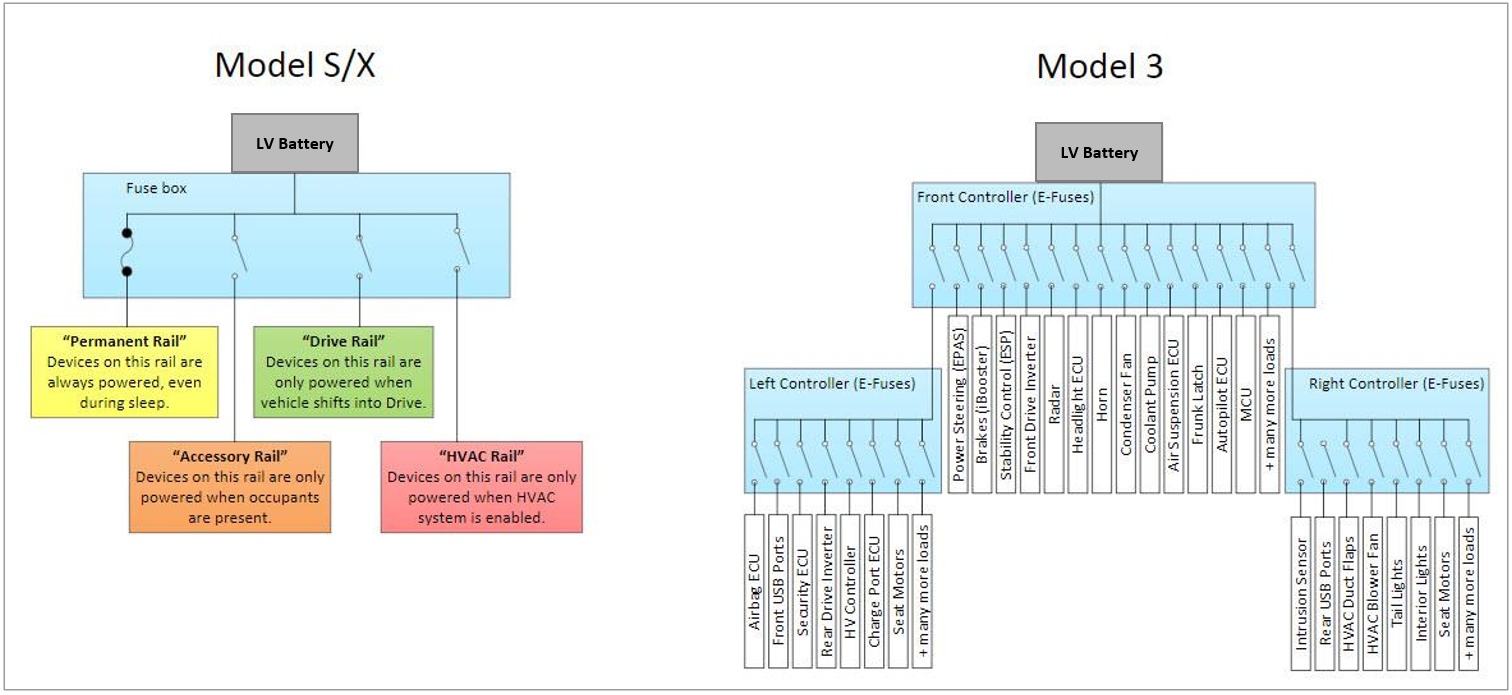
| Vehicle Power Management |
The concept of traditional power "rails" in the Model S and Model X does not apply to the Model 3. Instead, the Model 3 features individual E-Fuses which turn power on and off to each device individually. These E-Fuses can be "grouped" in firmware to create virtual power "rails" which are known as Vehicle States. The above graphic illustrates the differences in architecture.
Benefits of Model 3 topology:
- Devices are only powered on when absolutely necessary.
- Improves component longevity (long term vehicle reliability).
- Reduces vehicle power consumption (extends range) during Vehicle States (Drive, Sleep, Charge, etc.).
- Reduces overnight range loss due to "vampire current".
- Vehicle States can be updated over-the-air (OTA).
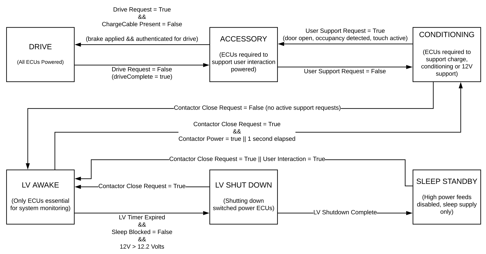
LV State Machinelink
The LV state machine could be considered the master state machine of the Model 3, since it powers the Front Vehicle Controller. Each state has implications on power distribution to vehicle components as well as influencing the state machines of other controllers, and inhibiting or triggering certain functions or processes. Below are some of the key LV state machine states, with brief descriptions relating to power management and examples of inhibiting or triggering processes.
Note
The transition examples are not the complete list, and there are intermediate states not captured in this section due to the complexity of the state machine.
Note
To learn more about state machines in general, a good starting point for research the term "Finite-State Machine"
 |
|---|
| LV States |
Sleep Architecturelink
During the vehicle Sleep state, many voltage devices are turned off to reduce loss of range when the vehicle is not in use. Devices capable of waking the vehicle from Sleep receive Standby power, as well as Autopilot for Telemetry and Electronic Power Assisted Steering (EPAS) to manage in-rush current. The chart below lists the ECUs that receive standby power during sleep, and which low voltage controller powers them.
Low Voltage Controller
Dependencies
Front Controller
- Gateway
- Autopilot
- Power Steering (EPAS)
- Air Suspension (Up-level Only)
- Battery Backed Siren (Europe)
Left Controller
- Security Controller
- Left and Rear Bluetooth Low Energy (BLE) Endpoints
- Charge Port
- Intrusion Sensor (Europe)
Right Controller
- Battery Management System (BMS)
- Right BLE Endpoint
Sleep Sequencelink
The vehicle will go to Sleep if it is not in use and there are no controllers that are setting a keep awake reason. Examples of keep awake reasons that are not related to direct user interaction (vehicle occupants, driving) are as follows: LV support request, charging, cabin overheat protection, preconditioning, and owner API requests.
When all the keep awake reasons are listed as NONE, the front vehicle controller and Gateway will send a "GoToSleep" message on all the CAN busses. When an ECU receives this message, it ends most processes and enters a low power state and becomes "CAN quiet". In this state, each ECU suppresses CAN transmits that are not wake up reasons, and receives or listens for CAN traffic from other ECUs in order to know when to wake up or abort Sleep. The final message to be transmitted is the command for the VEH CAN bus to go to Sleep.
In order for the vehicle to truly sleep, the low voltage battery current, measured by the Intelligent Battery Sensor (IBS) that is on-board the front vehicle controller, must first fall below 3 Amps. This will trigger the front vehicle controller to deactivate the high power E-Fuses it manages. The front vehicle controller then waits until the 12V Battery current drops below 500 mA before it turns off non-essential portions of itself, shutting down internal 12V and 5V rails. Finally, the microcontroller goes into a low power state.
During Sleep, there is some LV current draw through the Sleep bypass. This average current is reported after the vehicle wakes up by VCFRONT_sleepCurrent. While 500 mA is the minimum threshold for the Sleep state, it is high enough to drain the LV Battery to the point where it requires support relatively quickly. Ideal vehicles have an average sleep current of about 75 mA, while the majority of vehicles draw around 120-130 mA. There are many factors that affect LV current draw, the largest issues being 3rd party devices tapping into the Sleep Standby Supply.
Waking From Sleeplink
The Wake state inputs to the vehicle come from always-on loads that send a message to the front vehicle controller. The wake reason can be determined by inspecting vehicle CAN logs. Each controller that is capable of waking the vehicle will update its "wakeUpReason" signal when the controller wakes from Sleep and the Gateway resumes CAN logging.
The front vehicle controller will wake the vehicle if one of the following events occurs:
- The front controller detects the LV Battery needs to be charged.
- An always-on load sends a message to the front controller to wake
the vehicle, for example:
- The security controller detects a key
- A door handle is pulled
- SMS poke
- Current flowing through the battery monitoring integrated circuit exceeds a set threshold (set in firmware by the front vehicle controller micro).
Communication Architecturelink
Overviewlink
The various controllers on the Model 3 communicate with each other via one of the following: - CAN (Controller Area Network) - Used when high bandwidth, or low latency are required by an ECU. - LIN (Local Interconnect Network) - Used when high bandwidth. or low latency are not required by an ECU. - Video (Coaxial)
 |
|---|
| Model 3 Communication Architecture |
Bus Mappinglink
Model 3 CAN bus networks are mapped to different ID numbers depending on where they connect to the microcontroller within the gateway.
The following table states the canbus mapping of each car computer configuration:
| Bus ID | Car Computer PCBA PN 1479302-XX-X | Car Computer PCBA PN 1756000-XX-X |
|---|---|---|
| 0 | Vehicle | X |
| 1 | Party | X |
| 2 | Chassis | Party |
| 6 | X | Chassis |
| 7 | X | Vehicle |
CANlink
Overviewlink
A Controller Area Network (CAN) is a durable low cost communication standard designed to allow any device on the network to communicate with any other device without the need for a host computer. Each device ECU on a CAN network is connected by 2 signal-carrying wires (CAN-HIGH, CAN-LOW) with each wire carrying a complimentary signal waveform used to signify if the signal being transmitted is a logical 1 or 0.
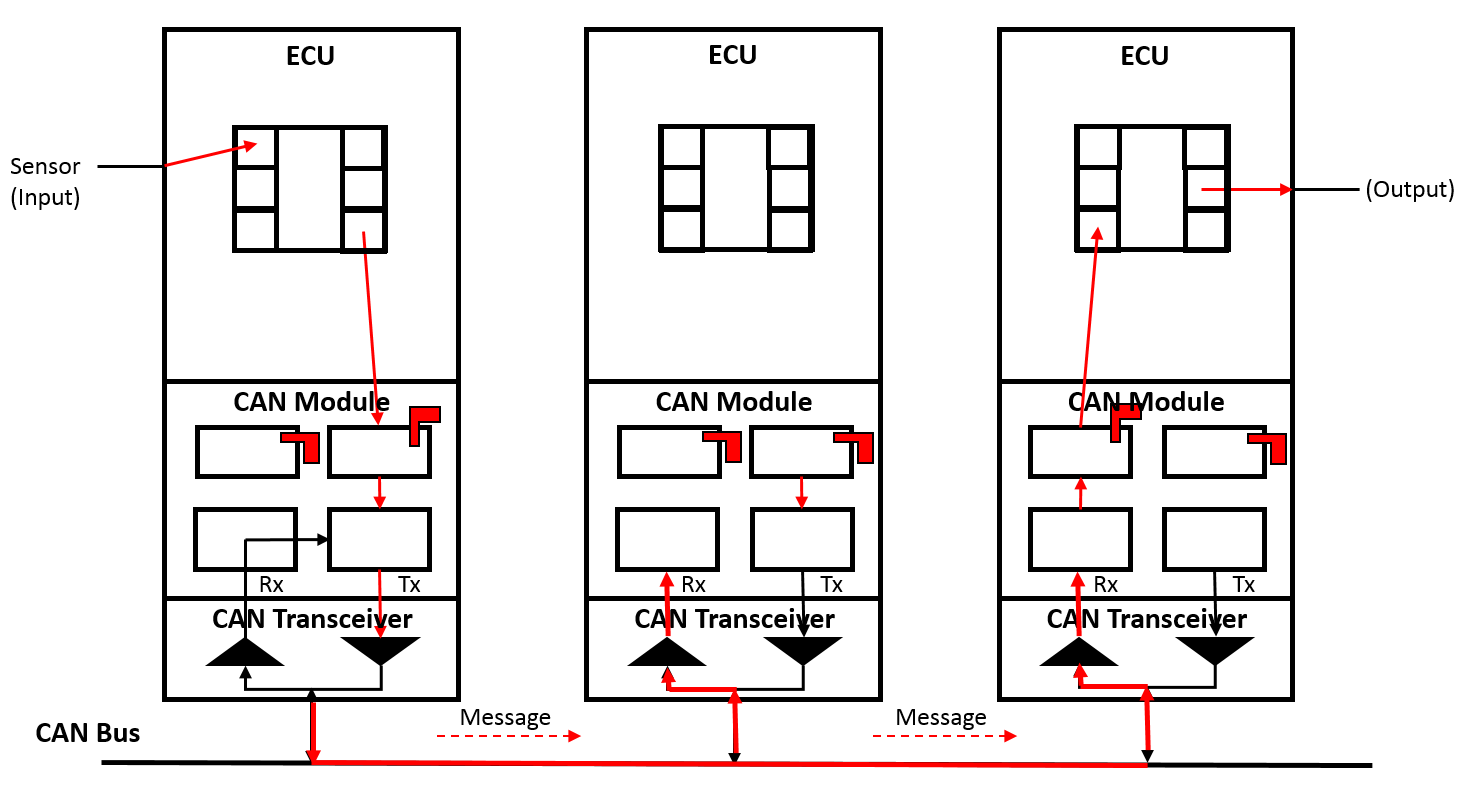
Transmitting and Receiving Datalink
First, a device connected to an ECU (like a sensor) detects some value. This value is then stored in the microcontroller input memory on the ECU. If this value is also required for another ECU connected to the network, it will be sent over the CAN Bus. Before this value can be sent, it is first copied to the transmit memory of the ECU. From there, the information goes to the transmit mailbox of the CAN module. If a current value is located in the transmit mailbox, it is indicated by the transmit flag (flag is raised).
Once the message is sent to the CAN module, it then checks via the Receive (Rx) line whether the bus is active (i.e. whether information is in the process of being exchanged on the network). If necessary, it waits until the bus is free before sending the message over the bus. All stations connected to the bus then receive the message as it travels over the Receive (Rx) lines to the receive areas of each of the CAN modules. All connected stations receive the message sent by the sensor and using the Cyclic Redundancy Check (CRC) checksum. The stations detect whether any errors have occurred in transmission. When a message is sent, a checksum is generated from all the bits and is included in the transmission, and the receivers all calculate the checksum from all the bits received using the same protocol. Once the received checksum is compared with the calculated checksum and no error are found, all the stations send an acknowledgement to the transmitter.
Finally, the correctly received message goes to the acceptance section of the associated CAN modules. From there, a decision is made whether the message is necessary for the function of the related control unit. If needed, the message is placed in the receive mailbox. Otherwise, it is discarded.
 |
|---|
| CAN-Bus Transmitting and Receiving Data 1. CAN Transceiver - The transceiver is a transmitter and receiver amplifier which converts the serial bit stream (logic level) of the CAN module into voltage values and vice versa. 2. CAN Module - The CAN module is what controls the data transfer process for CAN messages and is divided into two sections, the receive section and the send section. The CAN module is connected to the control unit via a receive mailbox or the send mailbox which correspond to memory locations on the microcontroller chip. 3. ECU - The ECU is the device that is receiving and processing signals from things like sensors and actuators and is the top level device in the stack. For example: The ESP, iBooster, EPB, etc. |
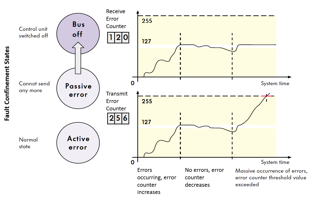
Error Managementlink
Since each message transmitted on the bus is received by each node on the bus, each node can check the validity of all the messages and post an error on the bus if a message is not valid. The tracking of these Tx (Transmit) and Rx (Receive) errors is how a CAN bus manages communication errors on the network. Using the broadcast process described in the section above, any device connected to the network that detects an error immediately notifies all other devices on the network by sending an error message called an "error frame," and the current message is then rejected by all devices on the network. This is then followed by an automatic repeat of the last transmission. If transmission continues to repeat due to continuously detected errors, an integrated error counter on each station will increase to track the error. If the preset threshold value for the error limit is exceeded (equivalent to 32 repeat transmissions), the affected ECU is informed and the CAN bus is switched off.
 |
|---|
| CAN Bus Error Counters |
Troubleshooting Issueslink
Measuring the Resistance on the Buslink
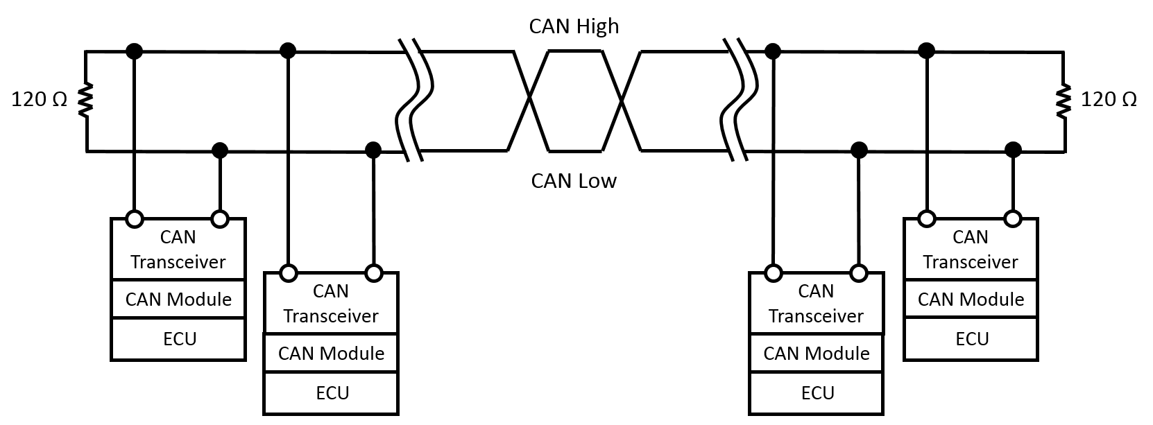
The most common CAN bus issue is either too much or too little termination resistance. In a low speed CAN network, each device connected to the bus typically has a 120 ohm resistor. In a high speed CAN network (which is what Tesla uses), only the ends of the main loops have a 120 ohm resistor. If the bus only has 2 resistors, the measured resistance between CAN-H and CAN-L will be 60 ohms. This is because there are two 120 ohms resistors connected in parallel. Conversely, if the bus has three 120 ohm resistors in the main loop, it will measure 40 ohms. With four resistors the measured resistance will be 30 ohms.
 |
|---|
| CAN Bus |
Note
The CAN bus must be powered down in order to retrieve accurate resistance measurements.
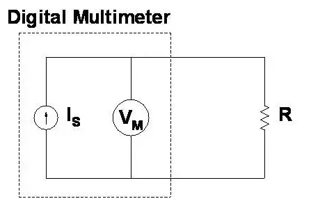
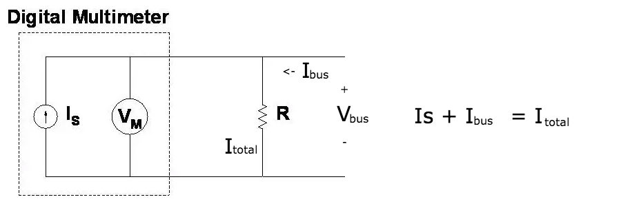
The reason the resistance measurement requires the CAN bus to be powered down is due to the way a Digital Multi-Meter (DMM) measures resistance. A DMM uses a constant current source to drive a known and fixed amount of current through the resistor that is being measured. In parallel, the voltage drop across the resistor is measured. The resistance is then calculated using ohm's law, V= I*R, solving for R. If there is another voltage source applied to the resistor, there will be an unknown current from the bus going through the resistor, changing the voltage drop and rendering the measurement by the DMM completely invalid.
 |
|---|
| Desired Operation |
 |
|---|
| Incorrect Measurement |
Terminationlink
There are two termination strategies in the Model 3, adjustable and fixed weak termination. Adjustable termination applies to all Model 3 vehicles with D or D2 level low voltage controllers, or generally vehicles manufactured prior to All-Wheel Drive (AWD) launch. Fixed weak termination applies to D3 level and later low voltage controllers, or generally vehicles manufactured post AWD launch.
The following chart details this key diagnostic information.
| Low Voltage Controller | D & D2.2 Level Build Configuration | D3 Level Build Configuration (or later) | D3 Part Revision |
|---|---|---|---|
| Front | ⅚ | 7 + | -G |
| Right | ⅘/6 | 7 + | -G |
Adjustable Termination
The Model 3 has the ability for configurable termination of select CAN buses through the body controllers. This ability permits self-testing of the CAN network prior to installation of the fixed termination points, normally on the Front and Rear Drive Units for the Vehicle and Private buses. The vehicle bus is terminated at the LH Vehicle controller and the Private bus is terminated at the front vehicle controller.
When the controllers are asleep or not powered, the termination point is open, meaning the bus resistance would be 120 ohms. The following chart shows the termination ECUs and their corresponding resistance values for Rear Wheel Drive vehicles. Adjustable termination points are denoted by "Adj" and are normally open (when the board is not powered, the resistance is open circuit).
| Controller | Vehicle | Private | Chassis |
|---|---|---|---|
| VCFRONT | - | 120-Adj | - |
| VCLEFT | 120 | - | - |
| VCRIGHT | 120-Adj | 120-Adj | - |
| Drive Inverter | 120 | 120 | - |
| Drive Inverter Slave | N/A | N/A | N/A |
| Infotainment Computer | - | - | 120 |
| Electronic Stability Program | - | - | 120 |
| Operating Bus Resistance - bus ON (ohms) | 60 | 60 | 60 |
| Measured Resistance - bus OFF (ohms) | 60 | 120 | 60 |
Fixed Weak Termination
In order to maintain self-test capabilities and CAN network stability, while simplifying the network and making it more robust, the architecture changed to "Fixed Weak Termination" at the introduction of D3 low voltage controllers and AWD launch.
In this architecture variant, the normally on adjustable 120 ohms termination points were changed to fixed 120 ohm resistors and the normally off adjustable 120 ohms termination points were changed to 720 ohms fixed resistors. This has the effect of slightly over-terminating the CAN bus, and the measured resistance will be slightly lower. However, because all the termination points are fixed, the network will always have the same resistance whether powered on or off.
The following charts show the ECU configuration with corresponding resistance values.
Rear Wheel Drive Vehicles
| Controller | Vehicle | Private | Chassis |
|---|---|---|---|
| VCFRONT | - | 120 ohms | - |
| VCLEFT | 120 ohms | - | - |
| VCRIGHT | 720 ohms | 720 ohms | - |
| Drive Inverter | 120 ohms | 120 ohms | - |
| Infotainment Computer | - | - | 120 ohms |
| Electronic Stability Program | - | - | 120 ohms |
All-Wheel Drive Vehicles
| Controller | Vehicle | Private | Chassis |
|---|---|---|---|
| VCFRONT | - | 120 ohms | - |
| VCLEFT 120 ohms | - | - | |
| VCRIGHT | 720 ohms | 720 ohms | - |
| Drive Inverter | 120 ohms | 120 ohms | - |
| Drive Inverter Slave | 720 ohms | 720 ohms | - |
| Infotainment Computer 120 ohms | - | - | 120 ohms |
| Electronic Stability Program 120 ohms | - | - | 120 ohms |
Measuring the Voltageslink
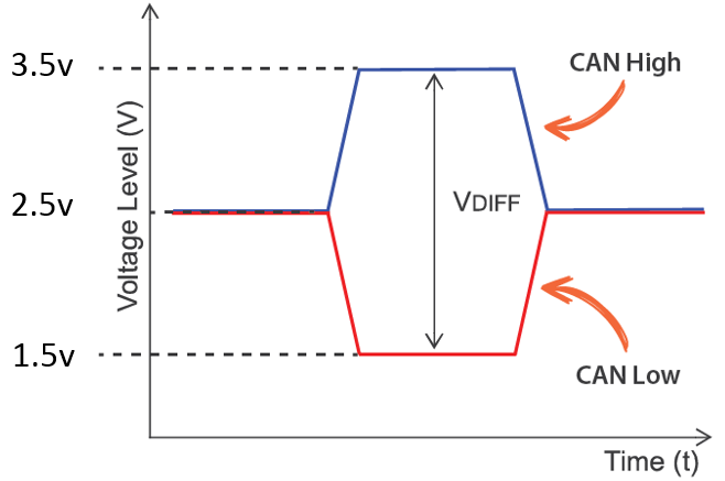
The voltage on a CAN-High wire usually fluctuates between 2.5V and 3.5V, while the CAN-Low wire usually fluctuates between 2.5V and 1.5V. The easiest way to see these voltage fluctuations is with a picoscope, but if a picoscope is unavailable, it is possible to measure the average voltage directly with a multi-meter. The measurement should be around 2.2V for CAN-Low and 2.7V for CAN-High.
 |
|---|
| CAN Bus Voltages |
Checking the CAN Bus Loadlink
There are no clear-cut rules for what the max bus load should be, but in general once the bus load increases beyond 70%, there is a possibility of data loss, or communication errors.
LINlink
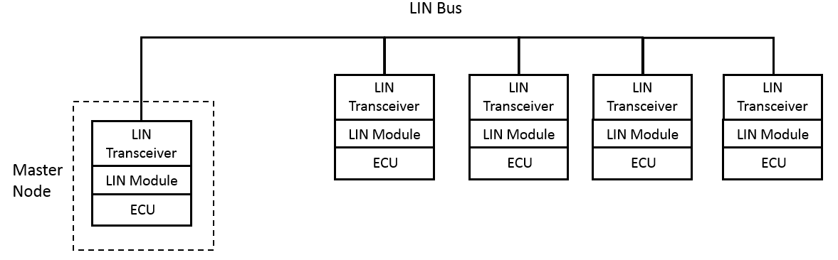
A Local Interconnect Network (LIN) is a low cost alternative to CAN, if speed or fault tolerance are not critical. Each ECU on a LIN network is connected to a master node with a maximum number of 16 nodes being connected to one master. Unlike CAN, devices on a LIN network are connected by one signal-carrying wire instead of two and operating at LV bus voltage instead of 5V like CAN. If a LIN bus is connected to a CAN bus, it is usually connected via a master LIN node.
 |
|---|
| LIN Network |