Structural High Voltage Battery Deviceslink
Last updated: December 11, 2024
Overviewlink
High Voltage (HV) devices are HV components within the HV battery that supplement the primary functions of the HV battery. They are individual devices that gate, manage, convert, transform, measure, monitor and control energy moving through the HV battery cell-array s.
The HV battery devices are located within an accessible section of the HV battery, referred to as the Ancillary Bay, because they are more likely to require servicing when compared to the cell-arrays within the platter.
Note
See Structural High Voltage Battery Theory of Operation for more details on the platter and cell-arrays.
The HV devices group contains the following :
| HV Device | Purpose |
|---|---|
| Power Conversion System (PCS) |
|
| HV Pyro-disconnect |
|
| Charge inlet connector | Connects PCS input to the charge port |
| HV fuses |
|
Device Clusterlink
Specificationslink
The device cluster is a self-contained unit which integrates smaller HV devices into one unit. The device cluster includes:
- High Voltage Controller (HVC)
- Two Pyro-disconnects (low side and high side)
- Two Pack-contactors (one positive and one negative)
- Fast charge contactor assembly
- Pin carriers for drive units
- Dual Pole Dual Throw (DPDT) assembly
- AC and DC harness to the Power Conversion System (PCS)
- HV compressor and accessory connectors
- HV compressor fuse
- HV accessory fuse
- Unswitched positive and negative HV DCDC fuses (always energized)
- Switched positive HV DCDC fuse (only energized when pack-contactors are closed)
The device cluster is located next to the PCS in the Ancillary Bay at the rear of the HV battery.
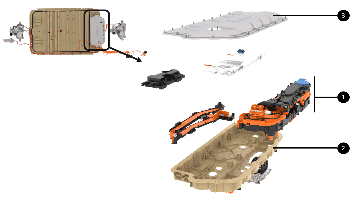 |
|---|
| 1. Device Cluster 2. Ancillary Bay casting 3. Ancillary Bay service cover |
| Location of Device Cluster |
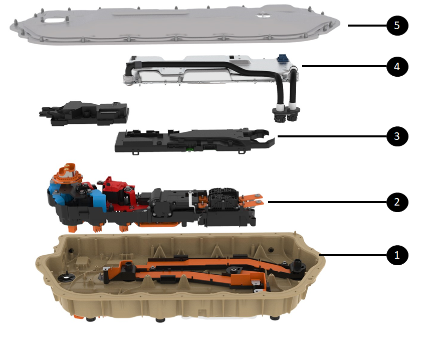
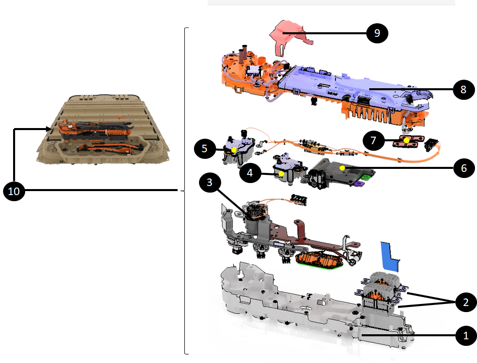
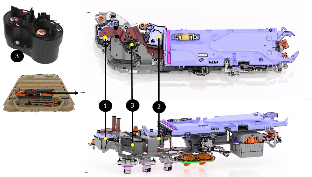
The rendering below shows an exploded view of the device cluster for visualization of its subcomponents and their location.
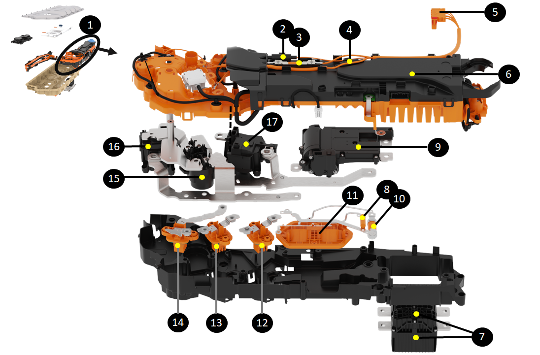 |
|---|
| 1. Device Cluster 2. Unswitched HV DCDC Fuse (1) 3. Switched positive HV DCDC fuse 4. Unswitched HV DCDC Fuse (2) 5. HV DCDC connector to PCS 6. HVC 7. Pyro-disconnects 8. HV accessory fuse 9. DPDT assembly 10. HV compressor fuse 11. HV compressor and accessory connectors 12. Right rear drive unit header for tri-motor configuration 13. Left Rear Drive header 14. Front drive unit header 15. Fast charge contactor assembly 16. Negative pack-contactor 17 . Positive pack-contactor |
| Subcomponents of Device cluster |
Operationlink
The device cluster operation includes all the operations performed by its internal components. Functions for each internal component is described below within their respective sections.
Serviceabilitylink
The device cluster is designed to be replaced as a unit in service via the Ancillary Bay access cover.
The internal components of the device cluster are not intended to be replaced separately.
Note
On the HV battery production line, the pyro-disconnects are installed at the same time the device cluster is installed in the pack. A different device cluster part number was created for service without pyro-disconnects pre-installed. This prevents working on live high voltage once the new device cluster is installed within the HV battery
Power Conversion Systemlink
Specificationslink
The Power Conversion System (PCS) is a contained unit located within the Ancillary Bay which hosts all the controls and power electronics to convert electrical energy. The PCS converts Alternating Current (AC) to Direct Current (DC), steps up or down DC voltage (otherwise known as DC to DC or DCDC), and converts DC to AC (only for the second generation PCS).
PCS includes:
- A cooling plate with coolant inlet and outlet
- A top cover
- A PCBA with transformers
- Heat sinks
- Connectors
There are 2 generations of PCS. See table below for specification differences.
| Gen 2 | Gen 1 | |
|---|---|---|
| Size (mm) | 612 x 254 x 56 | 705 x 281 x 85 |
| Volume (liters) | 8.7 | 16.8 |
| Mass (kg) | 7.8 | 9.5 |
| Processor | TI Sitara | |
| Electrical conversions | Two planar magnetic devices | Single DCDC and 3-phase board converters |
| AC charging current capability | 3-phase: 16A/Phase 1-phase: 48A/Phase |
3-phase: 16A/Phase 1-phase: 48A/Phase |
| AC continuous power (kW) | 11 | 11 |
| Bi-directional charging | Yes | No |
| Always on DCDC | Yes | No |
| DC operating voltage (Volt) | 340 to 850 | 200 to 500 |
| Number of DCDCs | Two distinct DCDCs:
|
Single DCDC |
| DCDC continuous power (kW) | 3 | 2.5 |
| DCDC peak transient power (kW) | 6 | |
| DCDC capability (Amps) | 400 | 200 |
| DCDC output range (Volt) | 24-58 | 8-16 |
The HV battery is equipped with a Gen 2 Power Conversion System (PCS2).
The PCS2 is located on the right side of the Ancillary Bay at the rear of the HV battery.
Note
See the Structural High Voltage Battery Theory of Operation for more details.
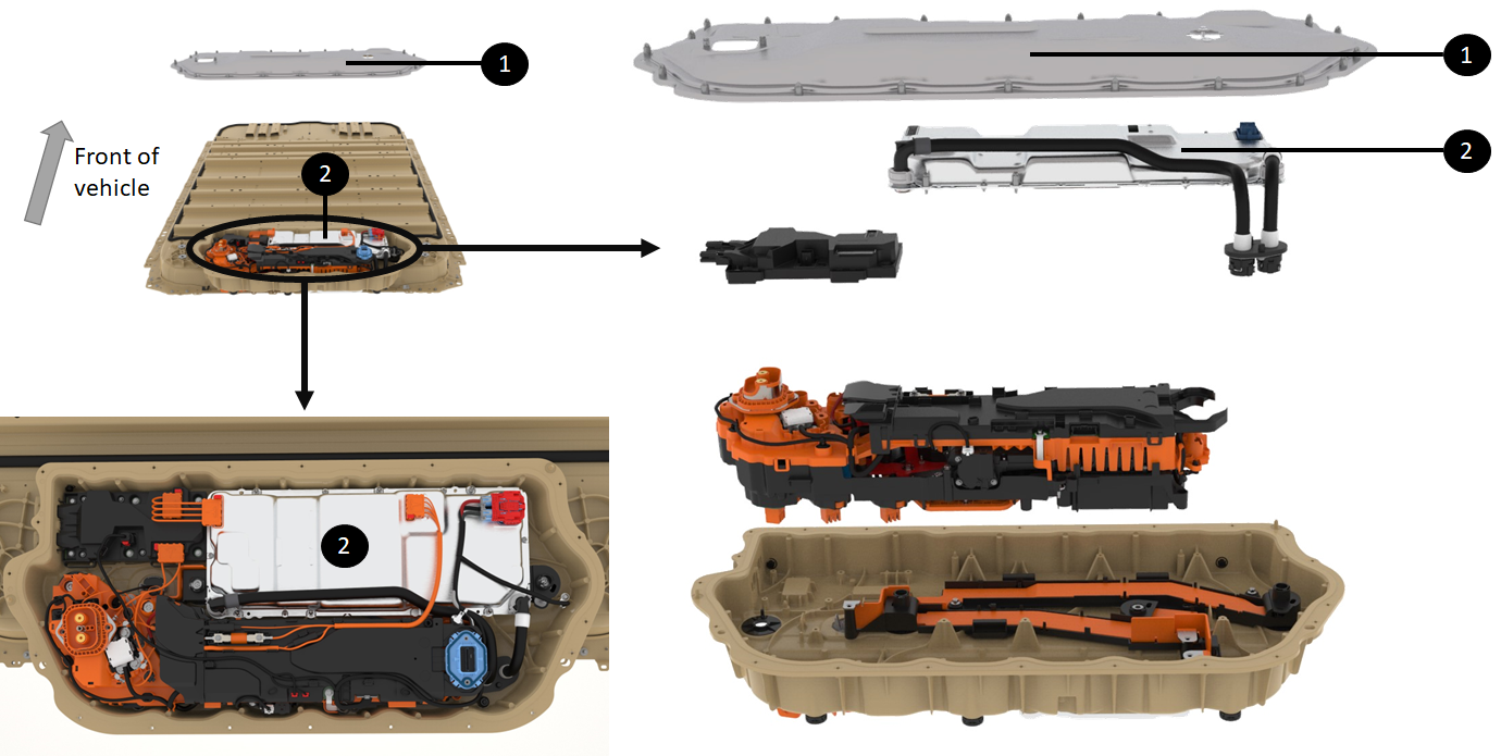 |
|---|
| 1. Ancillary Cover 2. PCS2 directly underneath |
| Location of the PCS2 |
Operationlink
The power conversion system performs the following operations:
- Converting AC to DC
-
Converting DC to DC
-
Converting DC to AC
Converting AC to DClink
When charging the HV battery on a Level 1 or 2 AC electric vehicle supply equipment (EVSE), the PCS transforms the wall power (120 VAC to 240 VAC) to a DC voltage corresponding to pack voltage (or slightly higher for the HV battery to charge). That voltage and current request comes from the HVC.
Note
See Structural High Voltage Software Management Theory of Operation for more details.
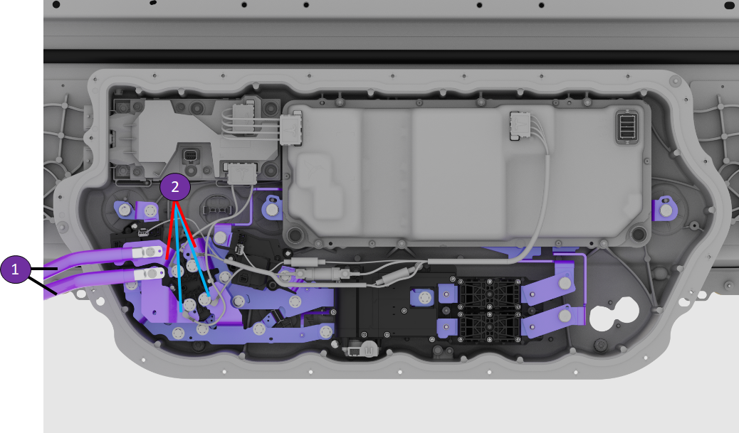
The rendering below shows the AC input connections in green coming from the charge port to the PCS via the AC junction box. The DC output connections in purple go to the HV battery DC link which is connected to the cell-arrays when pack-contactors are closed.
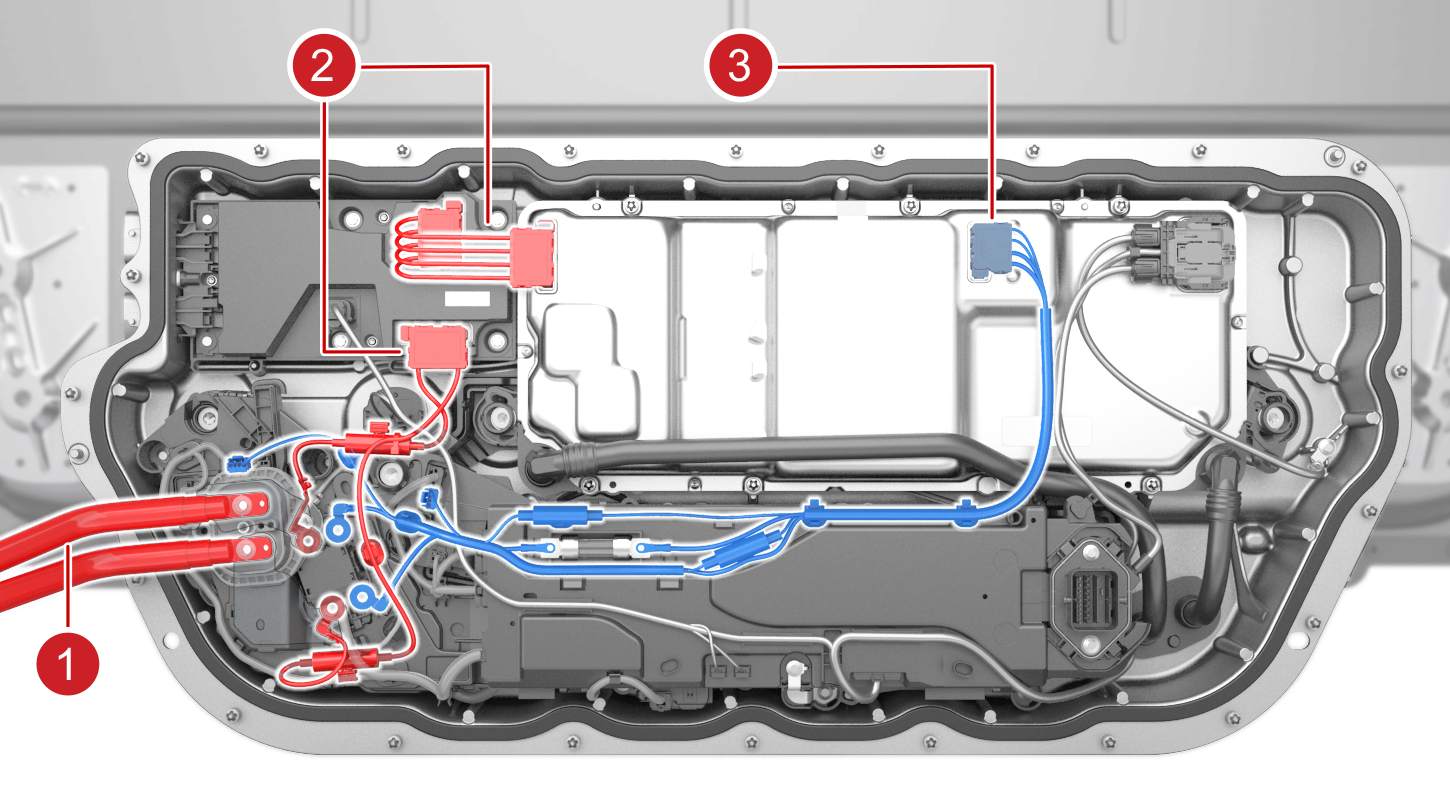 |
|---|
| 1. AC input coming from Charge port 2. AC input to PCS2 via AC junction box (passthrough) 3. DCDC output from PCS to DC link |
| AC to DC Charging via PCS2 |
During AC charging, PCS receives its charge request from:
- The HVC through Controller Area Network (CAN) or Etherloop
- A hardware enable line.
Both signals need to match in order for PCS to start converting power from AC to DC.
PCS2 is equipped with 4 AC terminals for line 1, line 2, line 3, and neutral. These lines are necessary to be able to AC charge from any AC power source in a wide voltage range.
PCS2 can support 3 phase AC input power. However, those 3 phases are shorted which only supports single phase AC charging.
Converting DC to AClink
Power Conversion System Gen 2 (PCS2) is not only able to charge on AC, but is able to supply AC voltage through the charge port and various power outlets built into the vehicle. Power is supplied from the HV battery to electric appliances using 120V or 240V 60Hz AC which is generated using PCS2 bi-directional capability.
Appliances are connected to the vehicle using outlets inside the cabin, the bed, or through the charge port using a bi-directional Universal Mobile Connector Gen 2 (UMC) with a UMC pigtail adapter that connects like an outlet to the UMC.
PCS2 gets the input power from the HV battery and outputs AC power through its 4 AC terminals which are connected to the AC junction box. From there, the power gets routed to the proper AC outlets (or charge port).
Converting DC to DClink
The Power Conversion System Gen 2 (PCS2) features 2 DCDCs. During drive, charge, or while parked with HVAC active, the 2 DCDCs work in parallel to power the mid-voltage bus which includes critical functions like steer-by-wire, braking, lights and others. The left vehicle controller (VCLEFT) will request switched DCDC support to the HVC.
When the vehicle is parked and HVAC is inactive, pack-contactors will open, and mid-voltage support will only come from the unswitched DCDC.
Using the unswitched DCDC saves energy while the vehicle is parked and provides power to:
- Close contactors
- Run HVIL/isolation checks
- Maintain thermal pumps running
- Support accessories and low/mid voltage circuits when there is an HV faults preventing contactor closure.
Unswitched DCDC power relieves pressure around software updates and mid-voltage battery energy capacity, allowing drive inverters to update software when contactors are opened (and thus HVIL status unknown).
Because PCS2 is always powered, it can close contactors with reduced energy from the medium voltage battery to precharge the HV DC link bus.
Power lines between the HV battery to both DCDCs are fused. The unswitched DCDCs have 2 fuses (one on positive and negative leg) whereas the switched DCDC only has one fuse.
Use VCLEFT_batterySupportRequest to monitor the request from VCLEFT to the HVC that switched DCDC support is needed for the mid-voltage circuits.
The renderings below show where the PCS gets power for both of its DCDCs.
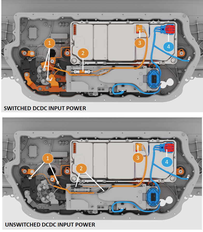 |
|---|
|
| DC to DC Electrical Wiring |
Serviceabilitylink
The PCS is replaceable in service as described in the repair manual. However, the internal components of the PCS are not serviceable. The entire unit gets replaced in service.
The replacement of the PCS does not require removal of the HV battery as the Ancillary Bay is accessible from the bed of the truck.
There are no specific calibrations or configurations to perform after installation of the new unit. However, a software redeploy is necessary after replacement to have the new PCS software version match the version that is installed on the vehicle.
High Voltage Controllerlink
Specificationslink
The High Voltage Controller (HVC) is a sealed plastic assembly with a large PCBA containing several processors to oversee cell management and high voltage distribution operations.
The HVC supports sensing, processing data from, and controlling HV components. The ECU name in software is HVBATT. HVBATT oversees the cells, the pack, and interactions with the vehicle along with the high voltage distribution.
Below is the general specification of the HVC in:
| Power Inputs | Receives HV input from cell-arrays (400V to 900V) and mid-voltage (MV) input from MV bus (36V to 50V) |
| Battery Monitoring Board (BMB) communication | To get BMB data (brick voltages and temperatures) |
| DPDT | Drives motor, receives position, current, and fault status data |
| Pack and FC Contactors | Manages coil pulse width modulation (PWM) to close, open, economize contactors and receives pack and DC link voltage sensing |
| Pyro-disconnects | Manages remote firing and monitors squib circuit resistance |
| Shunts | Measures HV battery current |
| Standby power supply | Outputs power to the MV bus (max of 20W and 52V) |
| PCS | Communicates via HVS CAN to monitor DCDC and AC charging operation |
| Charge Port ECU | Monitors charge port ECU fault line |
| ENS Signal (from RCM) | Receives restraint status in case of crash (to fire pyro-disconnects) |
| CAN and Ethernet | To communication with vehicle controllers |
The HVC is an internal component of the device cluster. The rendering below shows a standalone HVC, removed from the device cluster.
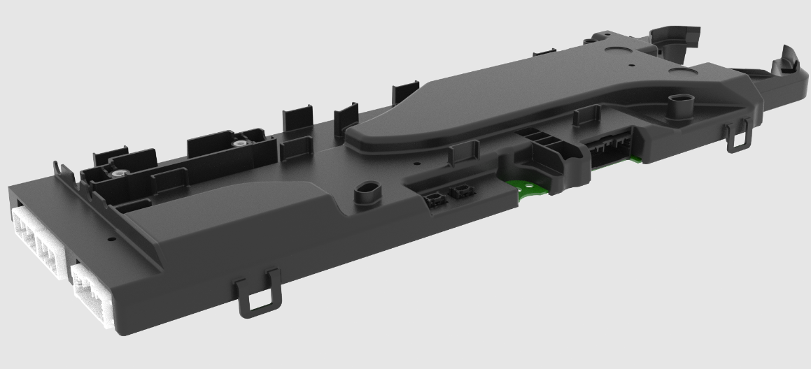 |
|---|
| High Voltage Controller (HVC) |
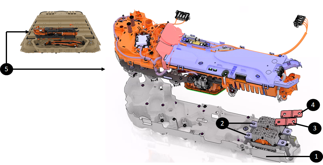
The illustration below shows the HVC within the Ancillary Bay and within the device cluster. The device cluster is directly accessible under the Ancillary Bay cover.
 |
|---|
| 1. Ancillary Bay casting 2. Device Cluster 3. HVC out of the device cluster (it is part of the device cluster but extracted on the picture) 4. PCS2 5. Ancillary Bay cover |
| High Voltage Controller (HVC) Outside the Device Cluster |
Operationlink
The HVC is the brain of the energy and power distributed to the vehicle.
It is built on a 4 quad processor system. The breakdown of duties per processor is as follows:
- HVBIG - The gateway application that manages Controlled Area Network (CAN) communication and Ethernet. HVBIG supports comms for the other 3 processors.
- HVPROC - The processor application that manages most of the algorithm and intensive math for state of charge, calculated amp-hour capacity, state of energy, and drive limits.
- HVMON - The monitoring application that manages power resets and ensures applications are running as expected. HVMON mostly manages contactor, charge state, state machine, HVIL, isolation, etc.
- HVCON - The main boot core and peripheral controller. It manages general-purpose input/output, analog-to-digital converter, battery management board communication.
To control the powertrain, the HVC relies on various measurements and data from the battery management board (BMB) and other HV devices systems. The HVC has groups of connections with the following devices:
| Component | Connector | Description |
| Shunt | X5006 | HVC knows the shunt resistance which allows it to calculate the HV battery current from the measured pack voltage across the shunt. The HVC integrates passive detection circuitry for over current events. If the shunt current measurement reported to the HVC is high enough, the passive circuitry within the HVC will trigger the pyro-disconnect. |
| Pyro-disconnect | X5003 | The HVC can trigger the pyro-disconnect squib to open the HV loop. The HVC monitors the resistance of that loop to confirm that the pyro is properly connected. When the pyro-disconnect is blown, the resistance of the pyro element is open and the HVC will report the pyro-disconnect as MIA. |
| Power Conversion System (PCS) | X5000 | HVC provides a 5V reference to PCS, enables DCDC and DCAC via dedicated lines, and communicates with the PCS via HVS CAN communication. |
| Charge port ECU | X5000 | HVC enables latching to the charging handle, communicates vis HVS CAN communication, and includes a dedicated wired connection to the charge port ECU. |
| Vehicle interface | X5000 | Restraint module CAN and Etherloop Standby power supply output Input power |
| Battery Management Boards (BMB) | X5001 and X5002 | HVC is connected to both sides of the BMB daisy chain. |
| Contactors and DPDT | X5003 | HVC drives the coil of the contactors, gets HV voltage sense, and gets power for unswitched DCDC. HVC drives motor of DPDT and gets voltage sensing from it. |
| AC Junction Box | X5000 | HVC provides logic input power to AC Junction Box and a dedicated serial peripheral interface link |
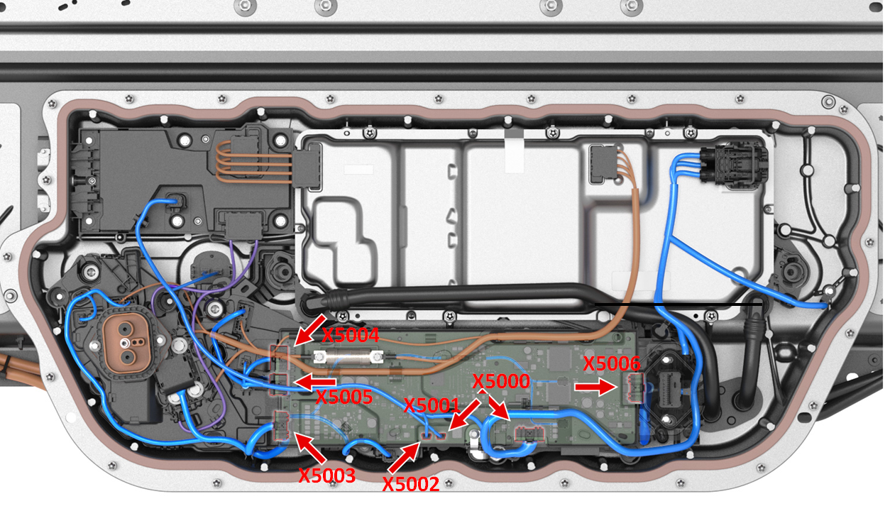 |
|---|
| Connector Reference on HVC |
As the brain of the HV battery, the HVC controls all functions and HV devices via software.
Note
See Structural High Voltage Software Management Theory of Operation for more details on the HVC software controls of the high voltage devices.
Serviceabilitylink
The HVC internals cannot be serviced. The HVC itself can be replaced by replacing the device cluster in the ancillary bay. The HVC on the Cybertruck is not compatible with other vehicle platforms. .
Note
The HVC holds non-volatile data related to the platter and other components in the Ancillary Bays. Therefore, when replacing the device cluster some data from the old HVC has to be copied over to the new one.
Pyro-disconnectlink
The pyro-disconnect is a standalone device able to interrupt the high voltage loop on the HV battery side of packs contactors.
Specificationslink
The pyro-disconnect is a busbar with a squib and pyro element. When fired, the squib breaks the busbar and opens the electrical connection.
The pyro-disconnect has an internal exhaust system that can dissipate the heat and particles generated by the arc when the HV connection is broken under heavy current. It is designed to be harmless when triggering in a person's hands.
The pyro-disconnect is located close to the HVC for optimized performance and reliability.
The HV battery embedded two pyro-disconnects in the device cluster, one per subpack. It is needed when the HV battery is in parallel mode for DC charging at 400V and two individual HV loops are running in parallel.
- The pyro-disconnect linked to the Cell-Array 4 is referred to as the high side pyro-disconnect or primary pyro.
- The pyro-disconnect linked to the Cell-Array 2 is referred to as the low side pyro-disconnect or secondary pyro.
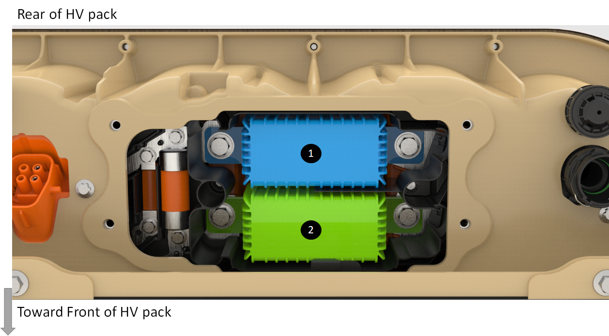 |
|---|
| 1. High side pyro-disconnect 2. Low side pyro-disconnect |
| Pyro-Disconnect in the HV battery |
The pyro-disconnects have high voltage bolted joints with the shunts on one side and DPDT on the other as shown below.
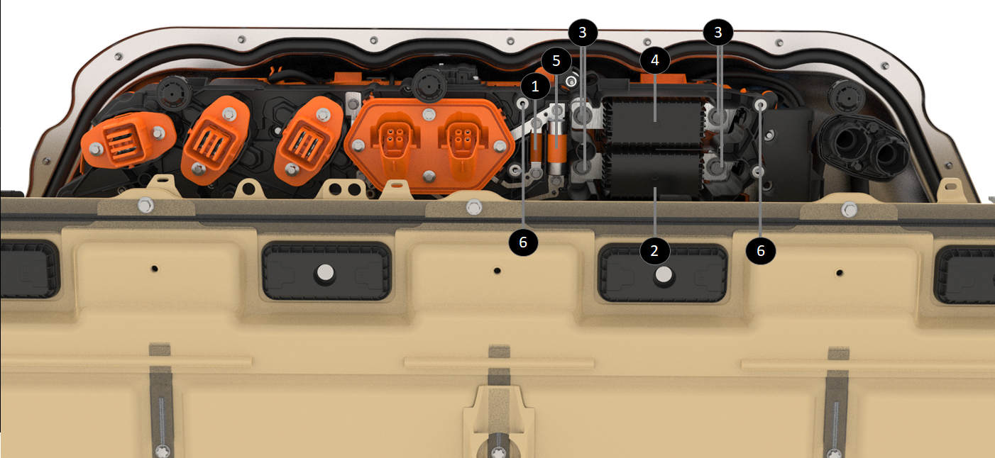 |
|---|
| 1. Fuse for accessory 2. Low side pyro-disconnect 3. Pyro-disconnect fasteners 4. High side pyro-disconnect 5. Heat pump compressor fuse 6. Fasteners (4) of the Pyro-disconnect service cover |
| Pyro-Disconnect Behind Service Cover |
Operationlink
The pyro-disconnect squib is triggered by the HVC via a dedicated wired connection. The HVC triggers the pyro-disconnect to interrupt the High Voltage loop for the following different conditions:
| Condition | Alert Log Signal | Description |
|---|---|---|
| Over current detected | PYRO_HANDLE_ OVER_CURRENT | There are two over-current detection mechanisms.
|
| Shunt MIA | PYRO_HANDLE _SHUNT_MIA | If the HVP is not receiving any current readings from the shunt, it will ask the HVC to trigger a graceful power off where discharge current will be ramped down, a message is displayed in the UI for the driver, and contactors will open 30 seconds after the graceful power off started. If that process failed, the HVP would fire the pyro after one minute. |
| Arc detected in contactor | PYRO_HANDLE_ PACK_POSITIVE_CTR_ARC PYRO_HANDLE_ PACK_NEGATIVE_CTR_ARC | The system has detected a significant voltage drop across a contactor when supposedly closed. |
| Impact detected | PYRO_HANDLE _ENS_CRASH | Impact signal is from the Restraint Control Module (RCM). The HVP is directly connected to the RCM. If that signal indicates an airbag deployment, the HVP will trigger the pyro-disconnect. The pyro-disconnect will have to be replaced after any collision or airbag deployment. The Emergency Notification Signal (ENS) is one wire from the RCM to the HVP. The ENS information is communicated by the frequency of the physical signal alternating between the high (6.6V) and low states (1.5V). When the RCM qualifies an impact, it transitions ENS PWM signal from 10Hz to 1kHz |
| Software over discharge current | PYRO_HANDLE_ OVER_DISCHARGE_CURRENT | The HVP will fire the pyro if the discharge current is above a certain threshold defined according to the config block which translates the type of HV battery connected to the HVC. That threshold is obviously below the hardware over-current. |
| Software over charge current | PYRO_HANDLE_OVER_ CHARGE_CURRENT | The HVP software will fire the pyro if the charge current is above a certain threshold defined according to the config block, which translates to the type of HV battery connected to the HVC. During charging, there is not passive over-current detection/protection. |
| Contactors need to be opened, but cannot | PYRO_HANDLE_ OPEN_IMMEDIATELY | The HVC software will fire the pyro if a condition requires the system to open contactors, but conditions are not met. Either the current is too high across contactors (contactors cannot open under high current), or contactors are welded, or there is no current value available, etc. Usually, this feature of firing the pyro when not suitable to open contactors is used after detecting an over temperature, a brick overvoltage, an undervoltage, or other conditions while current is too high to open contactors. |
Sequence of events for the pyro-disconnect to interrupt the HV loop:
- HVC triggers a current to excite the squib via connector (see item 6 below)
- The pyro element fires (see item 4)
- The busbar is pulverized (see item3),
- The arc inhibitor absorbs the arc generated by current interruption (see item 2):
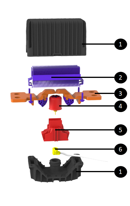 |
|---|
| 1. Pyro-disconnect housing 2. Arc inhibitor 3. Pyro-disconnect busbar 4. Squib / pyro element 5. Squib housing 6. Connector to HVP to trigger squib |
| Exploded View of HV Pyro-Disconnect |
Serviceabilitylink
Warning
There is always high voltage at the busbars connected to the pyro-disconnect (even with contactors open). Appropriate PPE is required for servicing, including eye protection in case of arcing or the pyro-disconnect firing during installation.
The pyro-disconnect cannot deploy if it is disconnected from the HVC, as the HVC supplies the current to trigger the squib. This means that the pyro-disconnects should always be removed before disconnecting it from the HVC or replacing the HVC.
The pyro-disconnects are part of the device cluster, but can be service independently. If the pyro-disconnects were not removed before the device cluster was pulled out, the pyro-disconnects would come out with the device cluster.
The HV battery features a dedicated service panel to replace the pyro-disconnects. It is accessible from under the truck without needing to drop the HV battery.
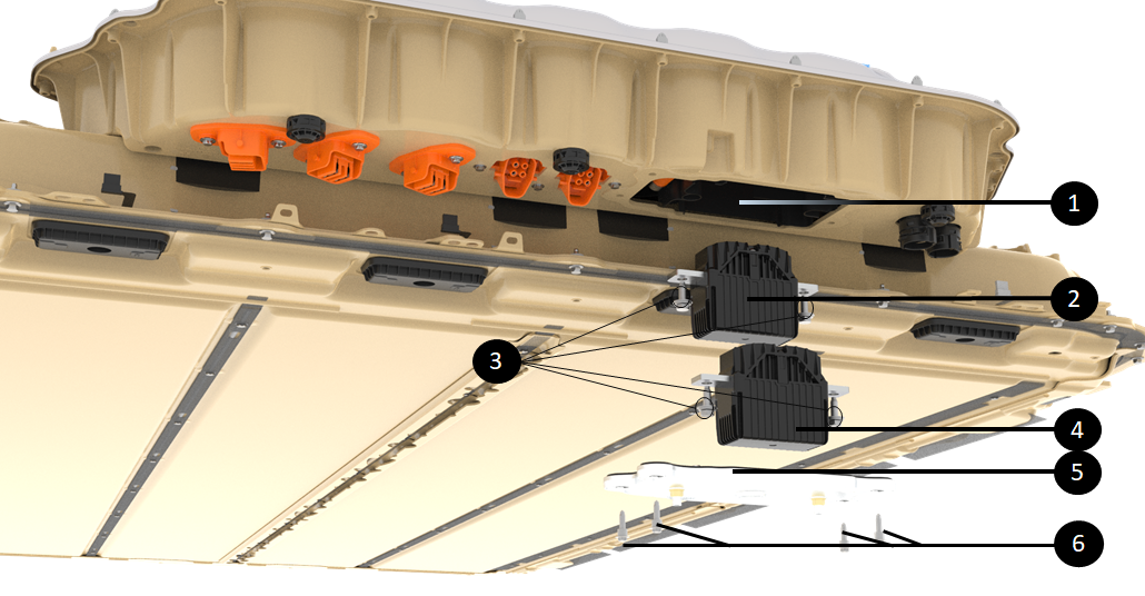 |
|---|
| 1. Pyro-disconnect cavern accessible from the underside of the Ancillary Bay 2. Low-side pyro-disconnect 3. Pyro-disconnect fasteners 4. High-side pyro-disconnect 5. Pyro-disconnect service cover 6. Fasteners (4) of the Pyro-disconnect service cover |
| Servicing Pyro-Disconnect From Underneath the Truck |
High Voltage Shuntlink
Specificationslink
The shunt is used by the HVC to measure current flowing in and out of the HV battery. The shunt is a copper busbar of a known precise resistance. The shunt does not have a microprocessor. On top of the shunt busbar is a small PCBA with passive electronic components to measure the voltage across the copper busbar and a connector for the harness to the HVC.
The HV device cluster has two shunts that individually measure each subpack current when the HV battery is in parallel mode for DC charging at 400V.
- The shunt linked to the Cell-Array 4 is referred to as the high side shunt
- The shunt linked to the Cell-Array 2 is referred to as the low side shunt
 |
|---|
| 1. Bottom tray of the device cluster 2. The 2 pyro-disconnects 3. High side shunt 4. Low side shunt 5. Device Cluster |
| Location of the 2 Shunts |
Operationlink
The shunt bar resistance, gain, and temperature coefficients are flashed onto the HVC during device cluster manufacturing line. Once the HVC knows the shunt bar resistance, it can determine the current flowing through the shunt from the measured pack voltage across the shunt.
Two wires connect the HVC to each shunt for the HVC to obtain the voltage across the shunt. Another pair of wires facilitates the passive hardware over-current feature described in the Pyro-disconnect section above.
Note
This pair of wires is also used as an auxiliary current sense. The HVC performs a sanity comparison of that current with the primary one to make sure that there is no hardware issue on either of those two current sense systems.
Two wires connect a small thermistor on the shunt bar to the HVC allowing the HVC to know the shunt bar temperature.
One last wire from the shunt to the HVC provides voltage input for the energy reserve in case the pyro was blown. When that occurs, the energy reserve is powered two cell-arrays, and one input is at the shunt.
Serviceabilitylink
The shunt in the HV battery is not replaceable in service on its own. It is part of the device cluster assembly needs to be replaced to replace one or both shunts.
HV Pack Contactorslink
The pack-contactors in the HV battery are the gate between the HV from cell-arrays and the rest of the vehicle.
Specificationslink
The pack-contactors are made of a single low resistance electrical contact point that moves along with a flexible busbar made of numerous thin layers of copper. The assembly connects to a movable rod that is in a magnet wrapped in a coil.
 |
|---|
| 1. Tray of the device cluster 2. The two Pyro-disconnects 3. Fast charge contactor assembly 4. Positive pack-contactor 5. Negative pack-contactor 6. DPDT (Dual Pole Dual Throw) 7. The two shunts 8. HVC 9. Insulator on top of positive contactor 10. Device cluster |
| Pack Contactors in the Device Cluster |
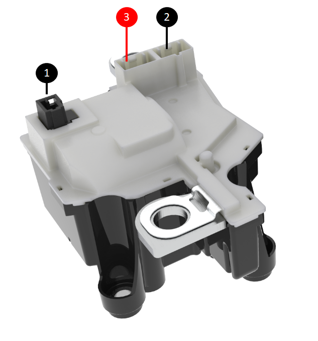
The pack-contactors have three connectors on the top face:
- One for the coil drive signal (to close and open the contactor)
- One for voltage sensing on both side of the contactor
- One for getting pack side power to PCS2 for the unswitched DCDC
 |
|---|
| 1. Connector for coil drive signal 2. Connector for voltage sensing 3. Connector for pack side power to PCS2 for the unswitched DCDC |
| Pack Contactors in the Device Cluster |
Operationlink
Current flowing through the coil creates a magnetic field that pushes the rod up. The pack-contactors have a massive coil which allows high force to close the contact, and the mass allows heat dissipation.
The pack-contactors are NOT designed to open under load. There is not enough spring force to pull the contact down when opening under load while arcing would try to bring the contact back together. Therefore, the system will not try to open contactors under high current if a fault occurs. The system will trigger the pyro-disconnect to first break the HV loop and then will open the HV battery contactors.
Serviceabilitylink
Pack-contactors are included in the device cluster.
To replace one or both pack-contactors, the device cluster needs to be replaced.
Fast Charge Contactorslink
Specificationslink
The fast charge contactors assembly is made of two contactors encapsulated in the same housing. The sense leads and contactor drive are included in a single connector at the top of the assembly between the two contactors.
Note
The fast charge contactors have a second redundant (auxiliary) switch to monitor the physical position of the contactor (open or closed).
When the fast charge contactor is in an "open" position, the switch should also be open and measure an open circuit across the terminals.
There have been cases where the contactors are open, but one of the contactor position monitor switches is stuck. This will still trigger fast charge contactor welded alerts.
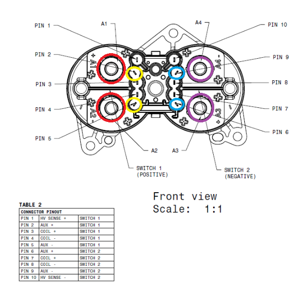
The diagram below points to the pin-out of the fast charge contactor assembly.
 |
|---|
|
| Pin-out of the Fast Charge Contactor Assembly |
 |
|---|
| 1. Negative pack-contactor 2. Positive pack-contactor 3. Fast charge contactor assembly |
| Fast Charge Contactor Assembly Inside the Device Cluster |
Operationlink
The fast charge contactor assembly connects the DC charge port inlet to the pack. This allows DC charging when the charging station or electric vehicle supply equipment (EVSE) is directly providing DC power to the pack.
The rendering below shows the DC power coming from the charge port, going through the fast charge contactors which shorts the DC link to the charge inlet:
 |
|---|
| 1. DC input power coming from fast charge port and EVSE 2. Fast charge contactors short positive charge inlet to positive DC link (red) and same for negative side (blue) |
| Fast Charge Contactor Assembly Inside the Device Cluster |
Serviceabilitylink
The fast charge contactor assembly is a unit. A single contactor cannot be replaced on its own, only the entire assembly gets replaced.
As seen above, the fast charge contactor assembly is located within the device cluster. Replacing the fast charge contactors is done with replacing the device cluster which is accessible under the Ancillary Bay service cover.