Charginglink
Last updated: March 29, 2023
Overviewlink
 |
|---|
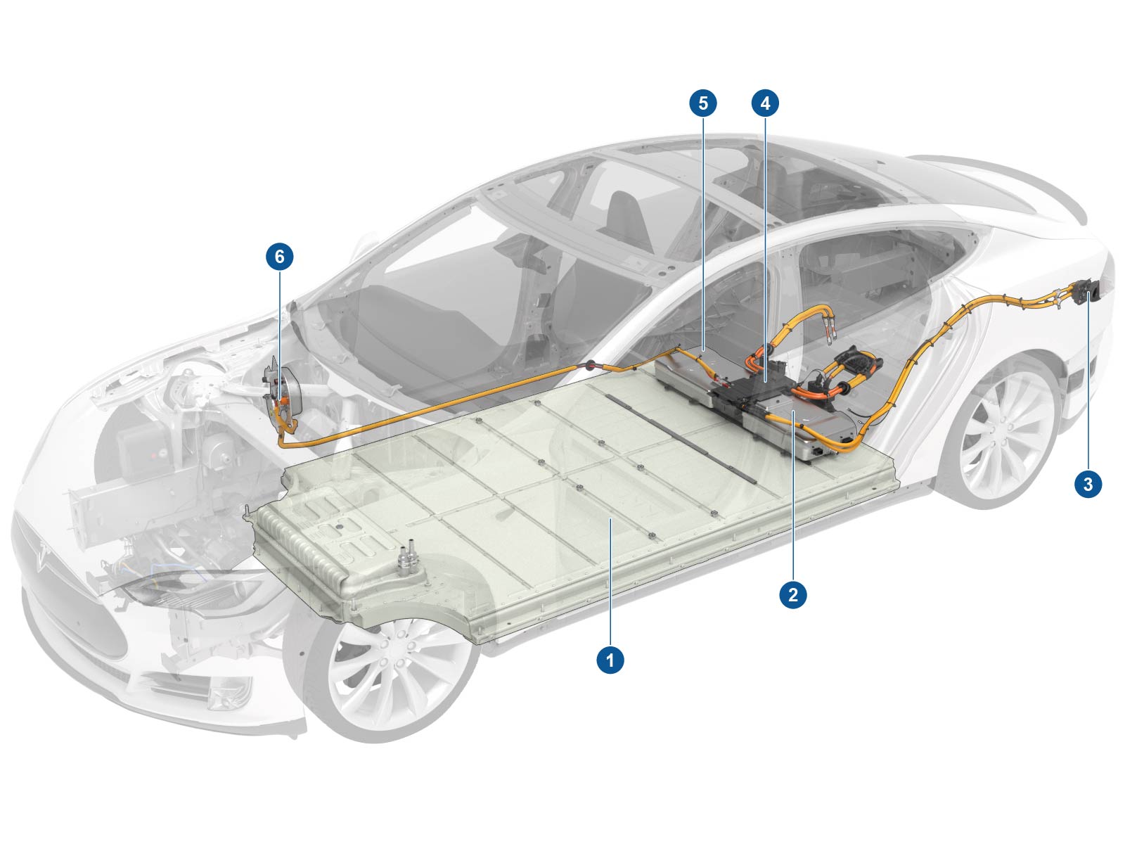
| 1. HV battery 2. 10 kW onboard slave charger (optional) 3. Charge port 4. Junction box 5. 10 kW onboard master charger 6. DC-DC converter |
| Component Location, Overview |
 |
|---|
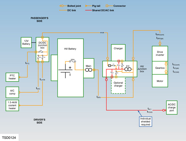
| High Voltage System Schematic |
The Model S is driven by an electric motor, which is powered by a high voltage (HV) Battery. The HV battery is available in the following capacities:
- 40 kWh
- 60 kWh
- 70 kWh
- 75 kWh
- 85 kWh
- 90 kWh
- 100 kWh
The HV battery must be recharged on a regular basis by connecting the vehicle to an external power source.
Note
If both the 12V battery and the HV battery become fully discharged, the 12V battery must be charged first, so that the charge port door can be opened.
Note
The HV battery can only be charged if its temperature is within a predetermined range. If battery temperature goes outside the normal operating range, the charge current might be reduced or charging might be completely inhibited until the temperature returns to normal.
The vehicle should be connected to a charging device whenever it is not in use. This ensures that the vehicle battery is always fully charged and the vehicle is ready for use.
The Model S comes standard-equipped with a mobile connector, and adapters to plug into commonly used power outlets. More adapters can also be purchased from Tesla. An optional Wall Connector can be installed in a customer’s garage and enables a vehicle equipped with twin onboard chargers to charge twice as fast as a vehicle with a single onboard charger.
To facilitate long distance driving, Supercharging is available for all vehicles equipped with the 85 kWh battery, and is optional for vehicles with the 60 kWh battery. The Supercharger outputs direct current (DC) and charges the battery at a much faster rate than other charging connectors are capable of — nearly 3 times as fast as a Wall Connector and twin chargers.
Component Descriptionslink
High Voltage Batterylink
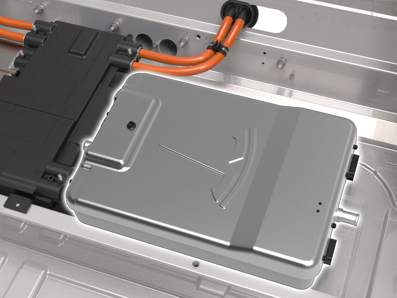
 |
|---|
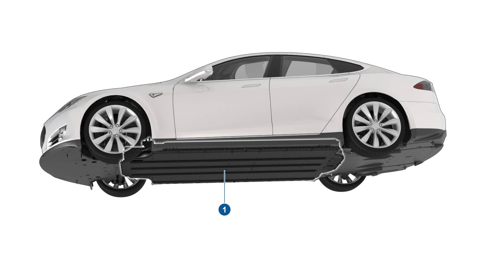
| 1. HV battery |
| High Voltage Battery |
The HV battery is located beneath the vehicle and is held in position by 34 bolts, which secure the battery to both the body and the subframes. The battery is a stressed member of the chassis, and gives the vehicle a flat underside and a very low center of gravity. This provides structural, aerodynamic, and handling advantages.
The purpose of the HV battery is to provide power to drive the vehicle and run all the accessory systems. It is the primary energy source for the vehicle. It supplies direct current to the drive inverter for propulsion, and to the DC-DC converter for support of the 12V electrical system. The DC-DC converter also functions as a high voltage junction block, distributing current from the HV battery to the A/C compressor, coolant heater, and cabin heater.
Chargers and Junction Boxlink
 |
|---|
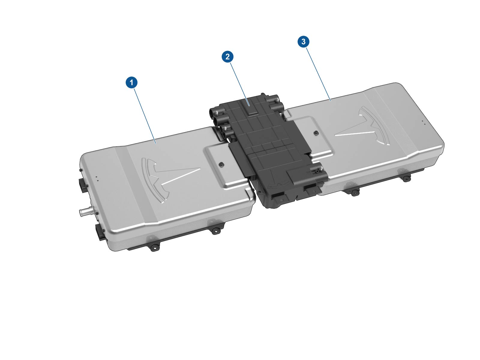
| 1. 10 kW onboard master charger 2. High voltage junction box 3. 10 kW onboard slave charger (optional) |
| Chargers and Junction Box |
Onboard Charger(s)link
 |
|---|
| Onboard Charger(s) |
The onboard charger(s) are located beneath the rear seat cushion. The right-hand master charger is fitted to all vehicles. Some models might have an optional slave charger fitted on the left-hand side. Each charger is secured to the floor panel by four studs and nuts.
If the slave charger fails, depending on the nature of the failure, the battery might still be able to be charged. If the master charger fails, charging is not possible.
The standard 10kW onboard charger is compatible with these input ranges:
- 85 - 265V
- 45 - 65 Hz
- 1 - 40A
- Peak charger efficiency of 92%
The optional 20 kW twin onboard chargers increase input capacity to 80A.
While recharging from an external AC source, the onboard chargers convert the AC to DC and control the flow of charge current to the HV battery depending on existing conditions, to ensure the HV battery is charged at the proper rate and to the correct SOC.
Note
No current flows through the onboard charger(s) during DC charging. However, the master charger is still crucial to the process, as it controls the fast charge contactors inside the HV Junction Box.
The temperature of the onboard charger(s) is regulated by the thermal management system, which controls the flow of coolant through the powertrain cooling circuit. For more information, refer to the Thermal Management Theory of Operation.
High Voltage Junction Boxlink
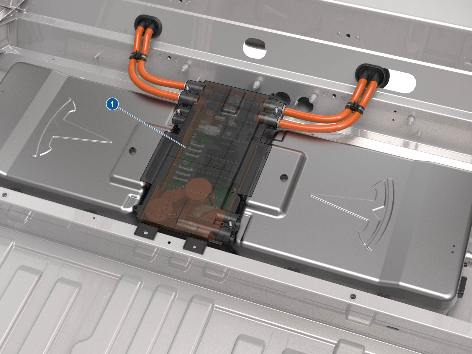 |
|---|
| 1. High voltage junction box |
| High Voltage Junction Box |
The High Voltage Junction Box (HVJB) is located beneath a cover plate under the rear seat. It is between the two chargers (if the optional charger is fitted) or to the left of the charger if only one is fitted. The junction box is secured by four bolts.
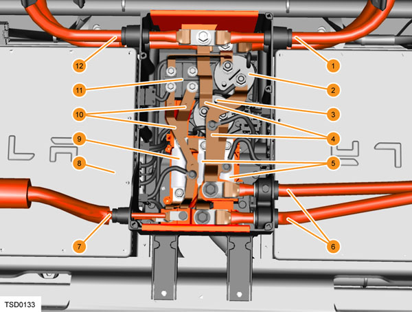 |
|---|
| 1. High voltage battery 2. B- contactor 3. B+ contactor 4. High current bus bars 5. 2 x 50 Amp fuses 6. Charge port 7. To DC/DC converter 8. 10 kW master charger 9. 100 Amp fuse 10. Low current bus bars 11. Noise filter 12. Drive inverter |
The HVJB allows current to flow between the:
- HV battery
- Drive inverter
- DC-DC converter
- Onboard charger(s)
- Charge port
A High Voltage Interlock Loop (HVIL) switch on the lid should disable the HV system when the lid is removed, but always follow the vehicle electrical isolation procedure in the Service Manual and verify that no voltage is present before beginning work.
The HVJB contains the fast charge contactors, which are controlled by the master charger, that close to create a direct link between the charge port and the HV bus. The contactors are normally open, and only close while Supercharging to allow current to flow directly to the HV battery. The HVJB contains three fuses:
- Two 50A fuse on the DC positive output (one for each charger).
- One100A fuse on the DC positive supply circuit that goes to the DC-DC converter.
If no slave charger is installed, the connectors are inserted into a holding fixture, and the vehicle harness connector is plugged into the dummy connector on the side of the HVJB, so that the HVIL and CAN circuits are complete.
DC-DC Converterlink
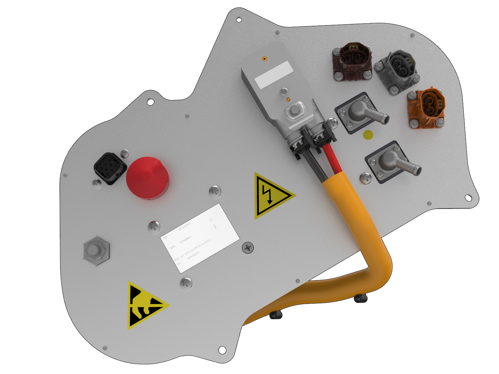 |
|---|
| DC-DC Converter |
The DC-DC converter is located in the front right-hand wheel arch, behind the wheel arch upper liner. It is secured in place by a bolt and two nuts. It is connected to both the 12V electrical circuit and the high voltage circuit.
Its purpose is to convert battery high voltage (350- 400VDC) to 12-13 VDC to power all of the vehicle’s low voltage requirements, and to maintain the charge of the 12V battery. It also serves as a HV junction box to distribute HV current to the:
- A/C compressor
- Coolant heater
- PTC heater
When the vehicle is on and the contactors are closed, the DC-DC supplies the current necessary to operate the entire 12V electrical system. When the vehicle is off and the BMS is in standby mode (contactors open), if the 12V battery voltage drops below 12.3V, the gateway module requests the BMS to enter support mode. In this mode, the BMS closes contactors and supplies current to the DC-DC converter, which in turn maintains the 12V battery within its nominal SOC range.
The temperature of the converter is regulated by the flow of coolant around the battery coolant loop. For more information, refer to the Thermal Management Theory of Operation.
Charge Settings and Deviceslink
The charging screen displays on the touchscreen whenever the charge port door is open. To display the charging screen at any time go to Apps > Charging. If the charge settings screen has been dismissed, bring it back by touching the battery icon again.
Warning
Repeated use of the MAX RANGE setting reduces the life of the vehicle battery.
-
Touch to select the desired charge level:
- STANDARD - This setting provides the best option for vehicle charging time and vehicle range. The HV battery is charged to approximately 90% of its total capacity, which helps to maximize battery life.
- MAX RANGE - This setting charges the HV battery to maximum capacity. The vehicle can then achieve the maximum range possible on a single charge.
Charging current is automatically set to the maximum value available from the charging device attached, unless it has been previously reduced to a value lower than the maximum available. The current level can be changed using the up and down arrow keys.
Note
Charging current cannot be set to a level that exceeds the maximum available from the charging connector.
Reducing the current level prevents the possibility of overloading the wiring circuit. This is particularly useful if charging from a domestic wall outlet that might be on a shared circuit with other connected equipment, or is rated lower than the current capacity of the charging connector.
A reduced charging current is automatically remembered the next time the vehicle is connected to a charging cable. If charging at a different location, a manual change to the charging current for that location must be made.
Note
Reducing the charging current increases the time required to charge the vehicle.
Off-Board Charging Equipmentlink
Three charging modes and devices are supported:
- Universal Mobile Connector (UMC)
- Wall Connector
- Tesla Supercharger (DC)
The UMC comes equipped with adapters to plug into the most common 240 volt outlet, standard 120 volt wall outlet, and public stations. The UMC can deliver up to 10 kW, or 31 miles of range, per hour of charging.
The Wall Connector and twin chargers can deliver up to 20kW, or 62 miles of range, per hour.
A Tesla Supercharger can deliver up to 90kW, or about 150 miles of range, in 30 minutes.
Universal Mobile Connectorlink
Warning
When charging the vehicle outside, remember to lock the vehicle before leaving it. The charge port light turns off, but the vehicle continues to charge with the security system activated.
Note
If the electrical outlet is unable to provide the current demanded by the Universal Mobile Connector (UMC), the circuit breaker protecting the electrical outlet might trip. If this happens, reduce the maximum current limit via the touchscreen.
The UMC is designed to give the added flexibility of charging the vehicle while on the road from a standard wall outlet. It is small enough to carry in the trunk. It operates on 110 - 240 VAC and gives a maximum of 40A of current when connected to a 240V/50A source. Maximum charging current is 12A when connected to a 110V/15A source.
Universal Mobile Connector Troubleshootinglink
 |
|---|
The UMC has a number of colored lights. Any problems during charging can be quickly identified by observing which light is flashing and the number of flashes. The following table provides more detail.
| Green lights | Red light | What it means | What to do |
|---|---|---|---|
| All lights on | Off | Charging in progress | Nothing. The UMC is successfully charging. |
| Top light on | Off | UMC is powered but not charging | Make sure the UMC is plugged into the vehicle. |
| Off | 1 flash | Ground fault: current is leaking through unsafe path | Should reset after 15 minutes. If not, make sure no one is touching the vehicle and then press the RESET button. |
| Off | 2 flashes | UMC failed the self test | Disconnect the UMC and press the RESET button. Reconnect the UMC. If the error persists, disconnect the UMC from the vehicle and power outlet. Reconnect to the power outlet and then to the vehicle. |
| Off | 3 flashes | Contactor failed | Disconnect the UMC from the vehicle and wait 10 seconds before trying again. If the problem persists, contact Tesla. |
| Off | 4 flashes | Ground lost | Make sure the UMC is properly grounded. If using a 120V outlet, make sure the hot and neutral pins are wired correctly. If uncertain, ask an electrician or plug a standard electrical receptacle tester into the outlet. |
| Off | 5 flashes | Sense circuit fault | Make sure the UMC adapter is attached properly. |
| Off | 6 flashes | Thermal fault | Consider charging inside a garage. |
| Off | 7-10 flashes | Pilot out of tolerance | Check charge connector for water intrusion. Blow out with compressed air. |
| Off | Off | Power lost | Disconnect the UMC and check that it has power. |
Gen 1 Wall Connectorlink
Warning
Regularly turn the power off at the control panel and inspect the charging cable and connector for signs of damage.
Warning
Ensure that the location of the charging cable does not obstruct pedestrians or risk being damaged by other vehicles.
The Wall Connector is installed on a 240 volt circuit and features a charging cable terminated in a 5-pin charge connector. The Wall Connector supplies up to 20 kW (80A at 240V).
The Wall Connector enables vehicles equipped with twin onboard chargers to charge twice as fast as vehicles equipped with a single charger. The Wall Connector ensures safe charging by using a switch that only connects line voltage to the vehicle when all conditions for charging are met. With 20 kW of power, a vehicle equipped with two chargers can recover 62 miles of range per hour of charging.
Self-Monitoring and Recoverylink
The Wall Connector has a ground monitoring circuit that continuously checks for the presence of a safe ground connection and automatically recovers from faults. Manual testing and resetting is not required. Temporary problems such as ground faults or utility power surges are overcome automatically, without the customer’s attention.
If a ground fault circuit interrupter fault occurs that interrupts charging, the Wall Connector automatically tries to clear the fault and re-attempts charging. This ensures that the vehicle is charged and ready for use when needed. If the problem is immediately sensed a second time, the Wall Connector waits 15 minutes before trying to charge. This process repeats eight times and if all attempts are unsuccessful, power is removed and no further attempts are made. In this case, a red error light on the front panel displays (See the Wall Connector Troubleshooting section for more information.). If a red error light displays, power off the Wall Connector and power it back on again.
Power Outageslink
If a power outage occurs, the Wall Connector automatically resumes charging when power is restored. If the charging cable is plugged into the vehicle when power is restored, the lights blink and the unit does not energize the charging cable for approximately 15 seconds to 3 minutes. This prevents the utility grid from experiencing a large surge when power is restored, allowing electric vehicles to begin drawing current at random times rather than all at once.
Wall Connector Self Test Modelink
- Cut the power supply to the Wall Connector and remove the front cover.
-
Use a pointed non-conductive implement, such as a plastic pen, to set the dip switches to the test setting as shown.
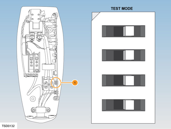
1. Dip switches Wall Connector Self Test Mode -
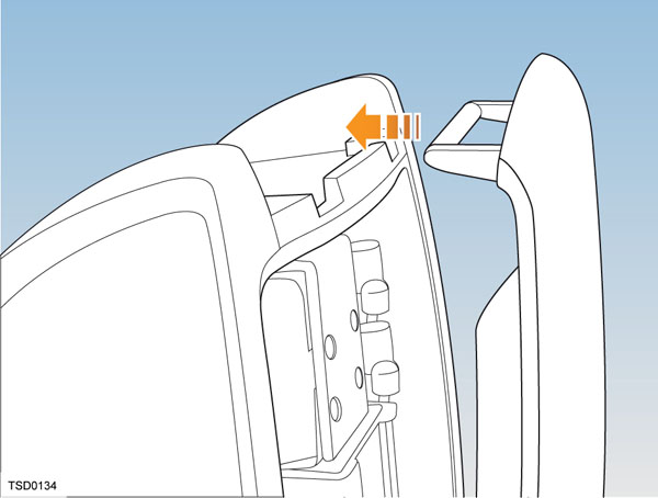
Locate the front cover over the top hinge.
-
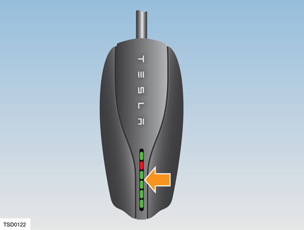
Turn on the power and hold the RESET button (shown below with an arrow) for five seconds. The contacts should audibly close and the lights sequentially display green.
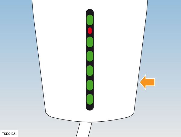
If the red light is on or flashing, refer to Wall Connector Troubleshooting.
If the red light is not on or flashing, refer to Setting Operating Current.
Wall Connector Troubleshootinglink
| Green lights | Red light | What it means | What to do |
|---|---|---|---|
| All lights on | Off | Charging in progress | Nothing. The Wall Connector is successfully charging. |
| Top light on | Off | Wall Connector is powered but not charging | Make sure the charge connector is plugged into the vehicle. |
| Off | 1 flash | Ground fault: current is leaking through unsafe path | Should reset after 15 minutes. If not, make sure no one is touching the vehicle and then press the RESET button. |
| Off | 2 flashes | Wall Connector failed the self test | Disconnect the Wall Connector and press RESET button. Reconnect the Wall Connector. If the error persists, disconnect the Wall Connector from the vehicle and power outlet. Reconnect to power outlet and then to the vehicle. |
| Off | 3 flashes | Contactor failed | Disconnect the Wall Connector from the vehicle and wait 10 seconds before trying again. If the problem persists, contact Tesla. |
| Off | 4 flashes | Ground lost | Make sure that the Wall Connector is properly grounded. Make sure the hot and neutral pins are wired correctly. If uncertain, ask an electrician. |
| Off | 5-6 flashes | Wall Connector requires servicing | Contact Tesla. |
| Off | 7-10 flashes | Pilot out of tolerance | Check the charge connector for water intrusion. Blow out with compressed air. |
| Off | 8 or more flashes | Wall Connector requires servicing | Contact Tesla. |
Setting Operating Currentlink
Warning
Risk of electrical shock. Before continuing, use a voltmeter to confirm that no power is available at the service wiring or terminals.
- Turn off the power source at the breaker.
- Open the front cover.
- Use a pointed non-conductive implement, such as a plastic pen, to set the dip switches to an appropriate operating current based on the type of breaker being used.
- Reinstall the front cover and turn on the power source to the Wall Connector.
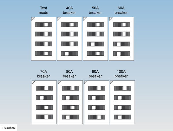 |
|---|
| Dip switch settings for type of breakers |
Tesla Superchargerlink
The Tesla Supercharger recharges vehicles quickly on road trips that exceed the range of a single charge. Superchargers are not intended for everyday use. Frequent use can result in minor reduction of the HV battery lifespan.
A Supercharger can deliver up to 150 miles of driving range in 30 minutes for an 85kWh battery.
Note
Supercharger compatibility depends on the model of battery the Model S is equipped with.
The Tesla Supercharger outputs 120KW total capacity, 90kW (225A @ 400V) maximum per vehicle connector.
Charging Timelink
Charging times vary based on the voltage and current available from the power outlet. Charging using a 40 amp, 240 volt outlet provides approximately 31 miles of range per hour of charge. Charge time also depends on ambient temperature and the vehicle’s HV battery temperature. If the battery is not within the optimal temperature range for charging, the thermal management system heats or cools the battery before charging begins.
Battery Lifelink
On average, the HV battery discharges at a rate of 1% per day. Situations may arise where the Model S is unplugged for an extended period of time. In these situations, keep the 1% in mind to ensure the battery has a sufficient charge level. For example, over a two week period (14 days), the battery discharges by approximately 14%. Discharging the battery to 0% can permanently damage the battery.
To protect against a complete discharge, Model S enters a low power consumption mode when the charge level drops to 5%. In this mode, the battery stops supporting the onboard electronics to slow the discharge rate to approximately 4% per month.
Once this low power consumption mode is active, it is important to plug the vehicle in within two months to avoid battery damage.
Note
When the low power consumption mode is active, the auxiliary 12V battery is no longer powered and can fully discharge within twelve hours. In the unlikely event this occurs, the 12V battery must be jump-started or replaced before the Model S can be charged.
Operationlink
Charging Procedurelink
 |
|---|
| Charge Port Door |
Position the vehicle as close as possible to the electrical outlet. The charging cable must be able to easily reach the charge port without putting a strain on either the electrical outlet or the charge port.
- The indicator LED on the unit should turn green to indicate that the unit is operating correctly and is ready to be connected to the vehicle.
- If the indicator LED turns red, a error has been detected. A error might occur if it is plugged into a damaged outlet or an outlet with insufficient power. Unplug and visually inspect the outlet. If no indicator is seen, the outlet might not be powered.
The flash speed pattern is inversely related to the State-of-Charge (SOC). When the SOC is closer to 100%, the flashing is slower, and when the vehicle is done charging, the charge port displays constant green. The flash speed is not related to the line current value or the charge limit setting. When the vehicle is locked and charging, the green LED stops flashing 2 minutes after vehicle lockout. When the vehicle is unlocked and charging, the LED is illuminated during the entire charging session. Once the vehicle is fully charged, the charge port LED switches to solid green. If there is no pilot signal, the LEDs turn off (for example, unplugging a UMC from the wall while connected to vehicle).
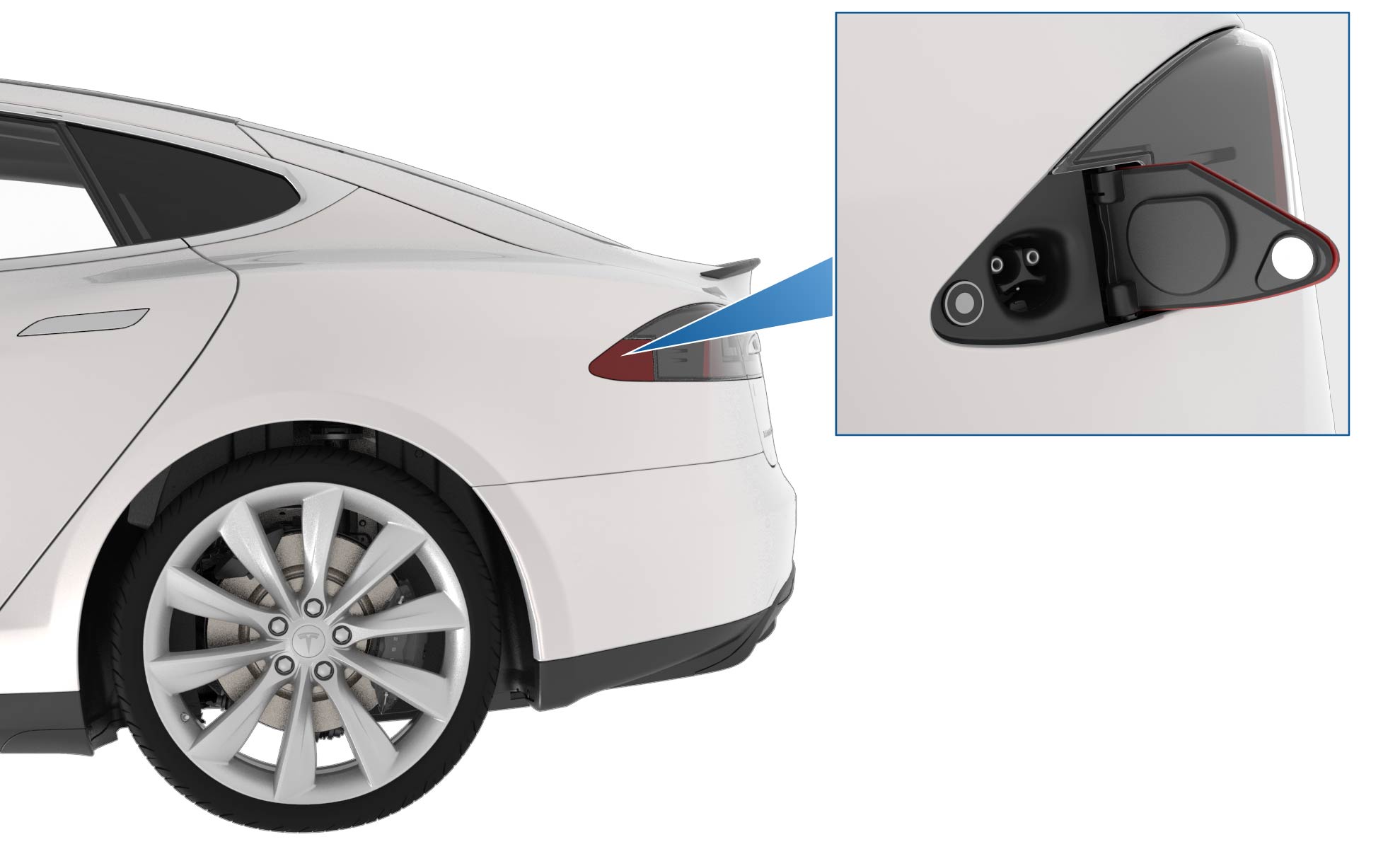
The charge port is located on the driver’s side behind a door which is part of the tail light assembly.
Note
The charge port door harness has a proximity signal resistor. If this fails, the vehicle cannot be charged. There is also a proximity resistor in the charge connector. If there is an issue with the proximity in the charge connector, the charge port latch does not raise to lock the connector in place.
When the charge connector is powered, pressing and holding the button on the connector sends a wireless signal to the vehicle to open the charge port door and drop the latch. The vehicle must be unlocked or have a recognized key in range for the charge port door to open. If the vehicle has poor reception, try aiming the connector at the back window of the vehicle.
If not using a Tesla charging cable, touch Controls > Charge Port on the touchscreen.
Note
The light ring around the charge port glows white when the door is open. If a charging cable is not connected, the latch raises after a time-out period of 5 minutes. If this happens, simply press the button on the charge connector again, or touch Unlock Charge Port on the touchscreen charging information screen.
Align the charging connector to the charge port and insert fully. A latch engages automatically to retain the connector. The vehicle does not enter drive mode while a connector is plugged into the charge port.
Once charging starts, the light ring on the charge port flashes green. If the light ring is pulsing yellow, charging current is limited to 16 amps. The most likely cause is the charging connector not being fully seated in the charge port, which prevents the latch from engaging the connector. Remove the connector from the charge port and reconnect it, ensuring it fully seats in the charge port.
If the light ring turns red, a fault has been detected. Refer to the touchscreen to see if more specific fault information is provided.
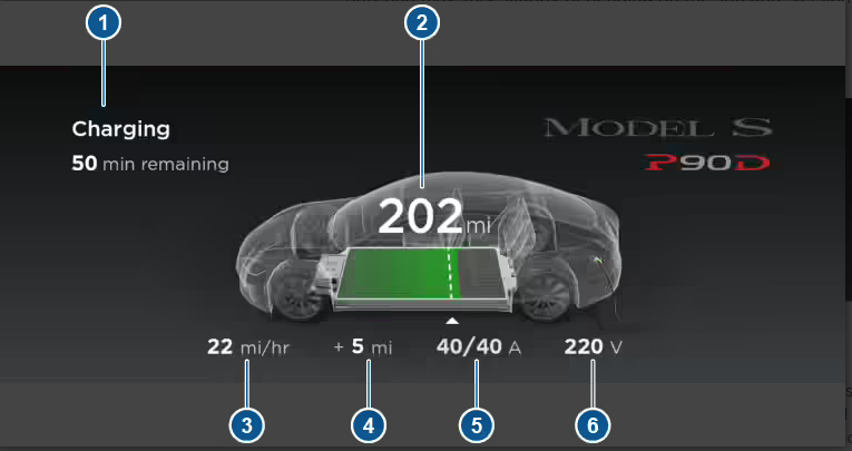 |
|---|
| 1. Charging status information 2. Total estimated driving distance (or energy) available. 3. Charging rate per hour 4. Range increase this charging session 5. Charging current/maximum current available from supply 6. Voltage of supply |
The instrument panel displays the current charging information.
As the battery nears a full charge, the pulsing of the charge port ring slows down. When charging is complete, the pulsing stops and the ring turns solid green.
When charging is complete, or to interrupt charging, push the button on the connector to release the charge port latch. The latch clicks as it disengages. Continue holding the button down and remove the cable from the charge port.
Charge Current Flowlink
The Model S can be charged using either an AC supply or a DC supply. The path that current follows once it enters the HVJB is different for AC and DC charging. DC charging is faster because it can supply nearly three times as much current as AC can.
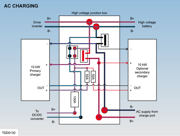 |
|---|
The vehicle recognizes when an AC charge source is connected using CAN communication with the Battery Management System (BMS). When charging from an alternating current (AC) source, current flows from the source through the connector to the charge port. From the charge port, it passes to the HVJB and is then routed by bus bars to the onboard charger(s). The chargers convert the AC to DC and supply current to the HV battery.
If the vehicle is equipped with twin chargers and connected to a Wall Connector, output is doubled to 20 kW. As battery SOC increases, charging current tapers off.
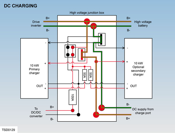 |
|---|
The vehicle recognizes when a DC charge source is connected using CAN signal supplied from the Supercharger to the BMS. This signal takes the form of a 5% duty cycle waveform on the pilot signal (generated by the Supercharger). The BMS sends a CAN message to the master charger, which then closes a set of contactors inside the HVJB.
Current flows from the Supercharger through the connector to the charge port. From the charge port, it passes to the HVJB and is then routed through the closed contactors to supply DC to the HV battery.
The Supercharger increases its voltage and current output to charge the battery with up to 90 kW, which tapers off as the battery state of charge increases.
Regenerative Brakinglink
Note
The regenerative braking setting is not available on all vehicles.
Regenerative braking (regen), is the conversion of the vehicle’s kinetic energy into electrical energy stored in the HV battery, where it can be used to drive the vehicle. The regen system is integrated within the motor and drive inverter and is designed to charge the battery. Control of the system is managed by the vehicle firmware and the drive inverter.
Regen typically creates an effect similar to the engine braking that is experienced when releasing the accelerator in a vehicle with a manual transmission.
When the vehicle is decelerating, the kinetic energy of the vehicle continues to turn the induction motor’s rotor. The firmware applies an AC field that is less than the synchronous frequency for that speed. Hence, current flows from the motor through the inverter and into the battery pack. This can amount to tens of kilowatts flowing into the battery, although the charge decreases with decreasing vehicle speed.
The quantity of regen braking available depends on many factors, including, but not limited to: vehicle speed, battery state of charge, operating temperature, and driver’s preference. Regen can be set to minimum on the touchscreen.