Wipers and washerslink
Last updated: September 30, 2022
Summarylink
The windshield wipers and washers are controlled by the Body Control Module (BCM), via the lever mounted on the steering column.
When a wiper speed is selected at the switch, the steering column control module sends a CAN message to the BCM. It then uses two relays to provide power to the appropriate terminal of the wiper motor, either slow or fast.
The motor drives the wiper linkage, which operates the wipers.
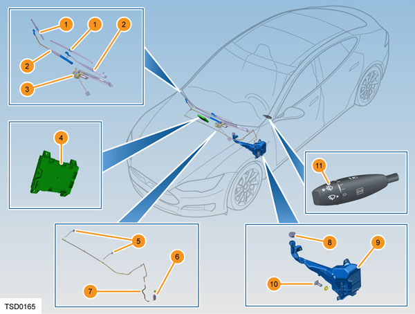
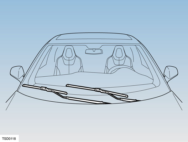
Component locationslink
 |
|---|
| 1. Windshield wiper blade 2. Windshield wiper arm 3. Windshield wiper motor and linkage 4. Body control module 5. Windshield washer jets 6. Windshield washer pump 7. Windshield washer tube 8. Windshield washer reservoir cap 9. Windshield washer reservoir 10. Windshield washer fluid level sensor 11. Windshield wiper and washer switch |
Component descriptionlink
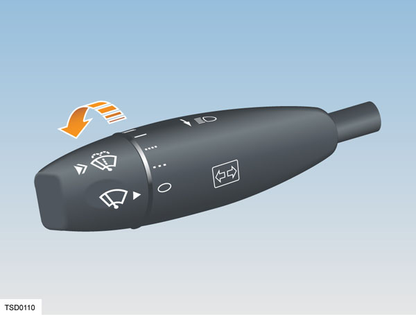
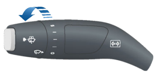
Wiper and Washer Switchlink
 |
 |
|---|---|
| Wiper switch on a vehicle without Autopilot | Wiper switch on a vehicle with Autopilot |
The wiper switch has 5 positions. Rotate to select the position required.
- Off
- Intermittent wipe - low sensitivity to rain
- Intermittent wipe - high sensitivity to rain
- Slow wiper speed
- Fast wiper speed
The washer switch is on the end of the lever and operates when pressed.
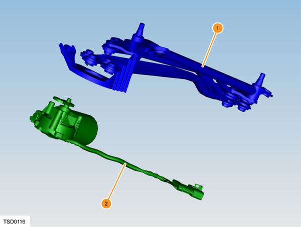
Wiper Motor and Linkagelink
 |
|---|
| 1. Wiper linkage 2. Wiper motor |
The wiper motor is mounted on a bracket that incorporates the linkage and the wiper arm spindles, and is secured with three screws. The motor and linkage assembly is located below the cowl screen panel in front of the windshield. The assembly is secured to the firewall by two bolts. A single electrical connector supplies the power to drive the motor.
The two-speed 12V brushed DC motor operates between 9V and 16V and between -40 degrees C (-40 degrees F) and 80 degrees C (176 degrees F). The motor speeds are 42 ± 5 rev/min for slow speed and 63 ± 8 rev/min for high speed.
Wiper Arms and Bladeslink
 |
|---|
The wiper arms are located by splines on the wiper arm spindles. Each is secured by a nut.
Each wiper blade is secured to its arm using a spring-mounted locking tab. Press the tab and slide the blade down the arm to remove it.
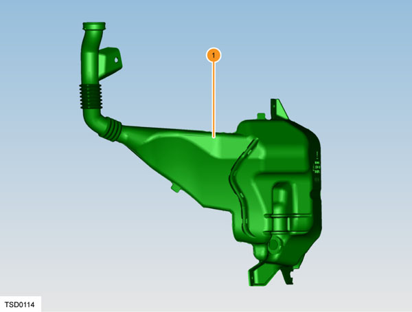
Washer Reservoirlink
 |
|---|
| 1. Washer reservoir |
The washer reservoir is located behind the liner in the left-hand front wheel arch. It is secured to the body panel by 3 nuts. The reservoir holds 5 liters of fluid.
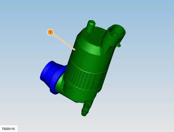
Washer Pumplink
 |
|---|
| 1. Washer pump |
The washer pump is mounted in the side of the washer reservoir. The left-hand upper wheel arch liner needs to be removed to gain access to the pump.
The pump is a push fit into the reservoir and is retained by a rubber seal.
The pump has a delivery pressure of 23.2 psi (1.59 bar) and a maximum current use of 4.5 amps.
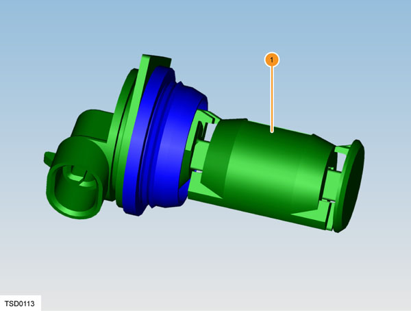
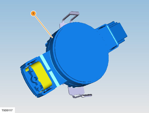
Low Washer Fluid Level Sensorlink
 |
|---|
| 1. Low washer fluid level sensor |
The low washer fluid level sensor is mounted in the side of the washer reservoir and is accessed by removing the left-hand upper wheel arch liner.
The sensor is a push fit into the reservoir and is retained by a rubber seal. The sensor contains an internally mounted float.
One pin of the switch is connected to a BCM output, the other pin is connected to ground. When it is immersed in fluid, the float is raised and the switch circuit is open. The BCM recognizes this as a normal state and takes no action.
If the fluid level drops below the level of the sensor, the float drops, the switch circuit is closed and the BCM output is pulled to ground. The BCM recognizes the low washer fluid condition and transmits a CAN message to display an alert to the driver.
Washer jetslink
The two washer jets are on the bottom surface of the hood. Each jet is secured by a clip.
 |
|---|
Operationlink
The wiper speed is controlled by the stalk with 5 speeds (Off, Interval Slow, Interval Fast, Continuous Slow, Continuous Fast). When the switch is operated, a CAN message is sent from the Steering Column Control Module (SCCM) to the Body Control Module (BCM). The BCM operates one of the two wiper relays to provide power to the appropriate terminal (Slow or Fast) on the wiper motor. Inside the motor, this power is applied to the low speed or high speed windings of the armature.
Motor speed controllink
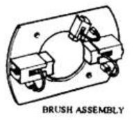
The wiper motor is a permanent magnet three-brush DC motor, which is driven through a worm gear to increase torque and reduce speed. The three brushes permit two speed operation.
Slow speed operation During slow speed operation, the BCM powers its 'Wiper Slow' output which, via the wiper relays applies 12V to the 'SLOW' winding of the wiper motor.
Inside the wiper motor, slow speed operation is achieved through the two brushes placed in the usual position opposite to each other.
Fast speed operation During fast speed operation, the BCM powers its 'Wiper Slow' and 'Wiper Fast' output which, via the wiper relays applies 12V to the 'FAST' winding of the wiper motor.
Inside the wiper motor, fast speed operation is achieved through the third brush which is installed closer to the earth brush (1 O'Clock). This design reduces the number of armature windings between them, which reduces resistance and consequently increases current speed.
 |
|---|
| Brush assembly showing the 3rd brush for high speed rotation at 1 o'clock |
Motor position controllink
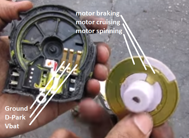
The wiper motor does not have an encoder so the BCM does not know the exact motor position. Instead, internal to the wiper motor is a "parking disk" which is mechanically connected to the motor shaft. This disk acts as a switch to turn off the motor when it approaches the home position. The disk connects the parking pin (D-Park) to either ground, nothing, or battery voltage depending on its position.
 |
|---|
The easiest way to explain how a wiper motor stops at the right position is by going through the 4 possible stages of the motor.
- Stage 1: Unparking the motor (Start movement)
- BCM powers relay K14/K123 by providing power via pin 'Wiper Unpark'.
- BCM applies 12V to either the 'SLOW' or 'FAST' armature winding of the wiper motor.
- At this point 'D-Park' does not connect to either 12V or ground by the parking disk but is instead connected to the SLOW winding of the motor via relay K14/K123. 2.Stage 2: Moving
- BCM continues to power relay K14/K123 as well as the SLOW or FAST winding of the motor.
- D-Park is connected to Vbat via the parking disk. 3.Stage 3: Parking (cruising towards home position)
- BCM stops powering relay K14/K123.
- Because K14/K123 is not switched, 12V is no longer provided to either of the armature windings of the motor.
- At this point 'D-Park' does not connect to either 12V or ground by the parking disk but is instead connected to the SLOW winding of the motor via relay K14/K123.
- As the + and - of the motor are shorted via the parking disk, the motor cruises towards its home position.
- Stage 4: Braking
- D-Park is still connected to the SLOW winding of the motor via K14/K123.
- The parking disk connects D-Park to ground shorting the SLOW winding to ground.
- This acts as an electronic brake.
Expected voltageslink
| BCM output | OFF | Interval | Slow | Fast |
|---|---|---|---|---|
| Wiper slow | 0V | Not moving = 0V Moving = Vbat | Not moving = 0V Moving = Vbat | Not moving = 0V Moving = Vbat |
| Wiper fast | 0V | 0V | 0V | Not moving = 0V Moving = Vbat |
| Wiper park pos sense | 0V | In park pos = 0V Close to park pos = almost Vbat Moving = Vbat | In park pos = 0V Close to park pos = almost Vbat Moving = Vbat | In park pos = 0V Close to park pos = almost Vbat Moving = Vbat |
| Wiper Unpark | 0V | Not moving = 0V Moving = Vbat | Not moving = 0V Moving = Vbat | Not moving = 0V Moving = Vbat |
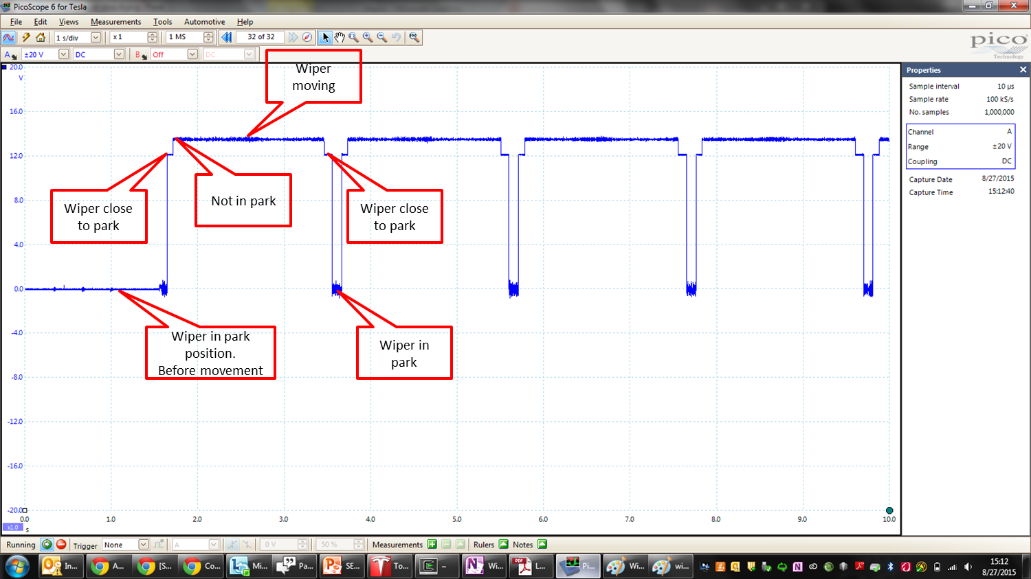 |
|---|
| 'Wiper Park Pos. Sense' on the BCM during continuous slow wiper speed |
Autowiperslink
The customer can select two interval wiper speeds on the wiper stalk. The amount of water that is allowed to collect on the windshield before a wipe is commanded depends on which interval position is selected. The first position is low sensitivity and allows more water to accumulate. The second position is high sensitivity and allows very little water to accumulate.
- non-DAS and DAS HW1 vehicles have a dedicated Rain Light Sensor installed behind the rear view mirror, see the RLS section for more information.
- DAS HW2 and later cars use the fisheye camera to detect the amount of rain and controls the wiper speed when Autowipers is turned on.
Note
The windshield wiper frequency and speed is automatically increased when the vehicle is moving, when either of the intermittent positions is selected.
Windshield Washerslink
Pressing and releasing the end of the lever will wipe the windshield once.
Pressing and holding the end of the lever will wash the windshield. The wipers also operate. Wash and wipe will continue while the end of the lever is pressed. When the lever is released, the wash stops and the wipers continue for four cycles.
Wiper heatinglink
If the Model S is equipped with the cold weather package, the wipers can be de-iced from the touch screen or from the mobile app. Wiper heaters automatically turn off after 15 minutes.
The wiper heaters consist of a defrost grid located in the lower section of the windshield. The BCM powers a relay that provides power to the front defrost grid.
Washer nozzle heatinglink
If the Model S is equipped with the optional cold weather package, washer nozzles have de-icers that turn on whenever the ambient temperature nears freezing, or when the heated wipers are turned on. The washer de-icers turn off when the heated wipers turn off (after 15 minutes), provided the temperature is warm enough to prevent freezing.
The BCM directly powers the washer nozzle heaters.
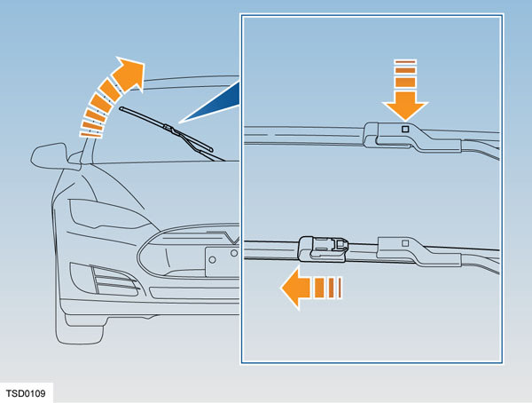
Wiper service positionlink
 |
|---|
The windshield wiper service position parks the wipers on the windshield. This makes it easier to change wiper blades, or free the wipers from frost/ice.
Activating the windshield wiper service position is done from the touchscreen under Controls > Service > Wiper Service Mode.
To deactivate the windshield wiper service position, the touchscreen or the wiper control can be used.
Warning
Wipers may freeze to the windshield during icy conditions. Do not operate the wipers if they are frozen to the windshield, as this may damage the wiper mechanism.
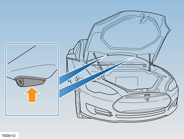
Rain and Light Sensorlink
 |
|---|
| 1. Rain/light/solar/humidity sensor |
The rain/light/solar/humidity (RLS) sensor is located on the inside of the windshield at the base of the interior rearview mirror.
The wiper speed is controlled by the stalk with 4 speeds (Interval Slow, Interval Fast, Continuous Slow, Continuous Fast), each position is mapped to a corresponding speed in the software.
The RLS sensor is an input to the BCM. The BCM monitors the ambient light level as measured by the sensor. When the light level drops below a certain threshold, the BCM turns on the headlamps.
Note
Vehicles built with DAS 2.0 hardware and later (October 2016) do not have a Rain Light Sensor. Instead, these vehicles have a Temperature Humidity Sensor (THS) Tesla HVAC Sensor. The THS does not detect rain. Rain detection is handled instead by the fisheye camera and a vision machine learning algorithm.