Vehicle Communication
Component Location
Networks
Controllers
- Autopilot Computer
- HVBATT: HV Battery controller
- Infotainment Computer
- VCLEFT: Left vehicle controller
- VCREAR: Rear vehicle controller
- VCRIGHT: Right vehicle controller
Harnesses
Communication Networks
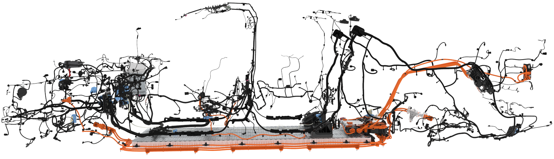
Cybertruck Communication Architecture Overview
In Cybertruck, there are numerous distributed computers that cooperate to control the vehicle's behavior. These controllers communicate locally with each other through many small communication networks. For messages to be shared throughout the vehicle, the small networks are connected to one large, high-speed Ethernet network called Etherloop. This new central Ethernet design replaces numerous main CAN networks (Body, Vehicle, Party, Chassis, Powertrain, etc.,).
Etherloop connects Infotainment, Autopilot, High Voltage (HV) battery, Left Vehicle Controller (VCLEFT), Right Vehicle Controller (VCRIGHT), and Rear Vehicle Controller (VCREAR). Developed to simplify and strengthen the vehicle communication network by reducing the amount of cross-vehicle CAN wires, Etherloop also adds message redundancy and increased logging capability. Each node connected to Etherloop has a specialized gateway to manage traffic flow, referred to as an Etherloop Generalized Gateway (EGG).
Etherloop
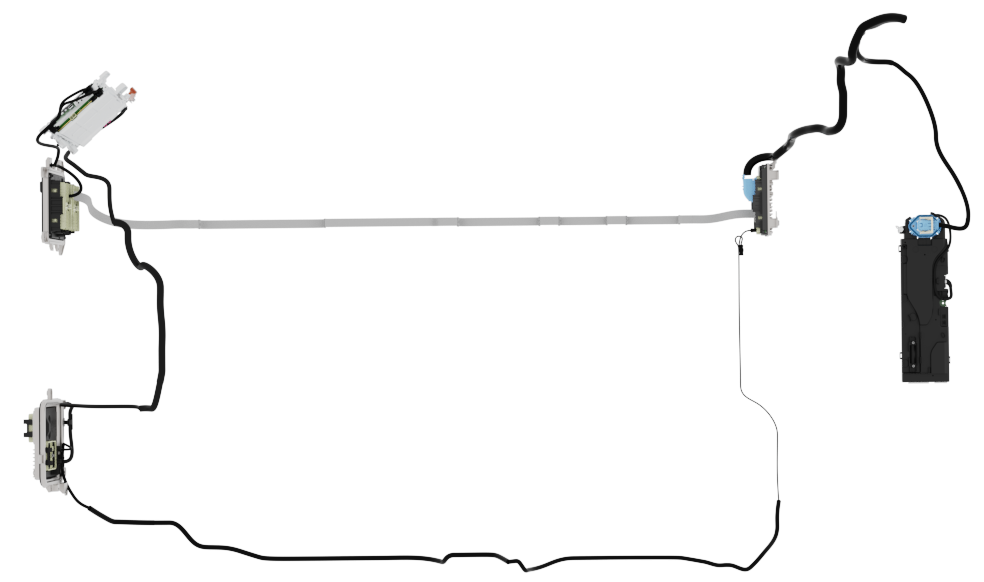
Etherloop Physical Network
Etherloop consists of six main Etherloop nodes connected in a loop formation by a shielded, twisted two wire Ethernet network between each node. The main nodes are the Gateway, Autopilot, HV Battery, right vehicle controller, rear vehicle controller, and left vehicle controller. The Media Contol Unit (MCU) and the Autopilot computer each use eight port Ethernet switches to connect to Etherloop. The vehicle controllers use a multicore (four 400 MHz cores) microprocessor with an integrated three port gigabit Ethernet switch. Two ports on the switch are connected outside the chip to Etherloop, and one port is connected internally. One of the cores of the multicore microprocessor is dedicated to managing Etherloop traffic, called the Etherloop Generalized Gateway (EGG). The other cores on vehicle microcontrollers run dedicated applications, like the Drive Inverter (DI) and Pedal Monitor (PM) in VCLEFT.
The Infotainment and Autopilot computers are connected by a board to board connector inside the car computer. The Etherloop connections between them travel through this connector.
Etherloop can be thought of as standard Ethernet with a custom Tesla-designed protocol built on top.
Etherloop Generalized Gateway (EGG)
Each node on the Etherloop has a switch to manage Ethernet traffic flow. On the vehicle controllers, the switch is controlled by an EGG. The EGG allows the node to talk bi-directionally around the Etherloop communicating to the next EGG using Ethernet protocol. Attached to the EGGs are numerous CAN networks and interior networks to communicate to other cores. The EGG is responsible for monitoring traffic as a gateway and ensuring a message is routed to where it needs to go. The EGG also acts as a translator that can convert frames between Ethernet and CAN. The EGGs also handle message security and constantly monitor network conditions. Data is sent between controllers using the CAN frames.
Example Etherloop flow:
- An Etherloop frame travels on the Etherloop and comes into the EGG switch.
- The EGG checks the Ethertype of the frame. Unknown Ethertypes are dropped.
- The EGG holds that frame and waits for the other duplicated frame to come in. Once it arrives the second frame is dropped.
- The EGG validates that the frame is secure.
- The EGG extracts the payload from inside the frame.
- The EGG then sends the messages from the payload to the appropriate destinations.
Duplicated Messages
On the Etherloop, critical vehicle traffic is duplicated and then sent in opposite directions around the Etherloop: clockwise and counter-clockwise. Each node is then responsible for dropping the second copy of a message it has already received. If a node receives only one message, it will suspect there is a problem with part of the network and set an alert.
Battery Pack (BP) CAN
- Description: Battery Pack CAN bus between vehicle and the High Voltage (HV) Ancillary Bay.
- Baud rate: 1Mbps
Drive Inverter Front (DIPF) CAN
- Description: Private CAN bus between the front drive unit and the DI/PM application in the left vehicle controller.
Drive Inverter Rear (DIPR) CAN
- Description: Private CAN bus between the rear drive unit and the DI/PM application in the left vehicle controller.
Infotainment Ethernet Bus
- Description: Infotainment Ethernet
- Baud rate: 500kbps
High Voltage System Bus
- Description: High Voltage (HV) system bus
- Baud rate: 1Mbps
Left CAN
- Description: Left domain communication bus connecting steering and airbag controllers.
- Baud rate: 500kbps
Left Body Bus
- Description: Left body communication network that connects the Vehicle Security (VCSEC) module and the Left Vehicle Controller (VCLEFT) to the left-side door handles.
- Baud rate: 500kbps
RCM Private Bus
Right Bus
- Description: Right domain communication bus connecting brake and steering controllers.
- Baud rate: 500kbps
Rearsteer Bus
- Description: Rear Steer CAN
- Baud rate: 500kbps
Right Body Bus
- Description: Right Body CAN
- Baud rate: 500kbps
Thermal Bus
- Description: Thermal CAN
- Baud rate: 500kbps
Serviceability
The EGGs are able to detect numerous communication issues, both with Etherloop and with connected CAN networks. Diagnosis is based on vehicle alerts, mainly reported from the separate EGGs. Start any diagnosis with checking for the presence of a052_EtherloopError.
a052_EtherloopError
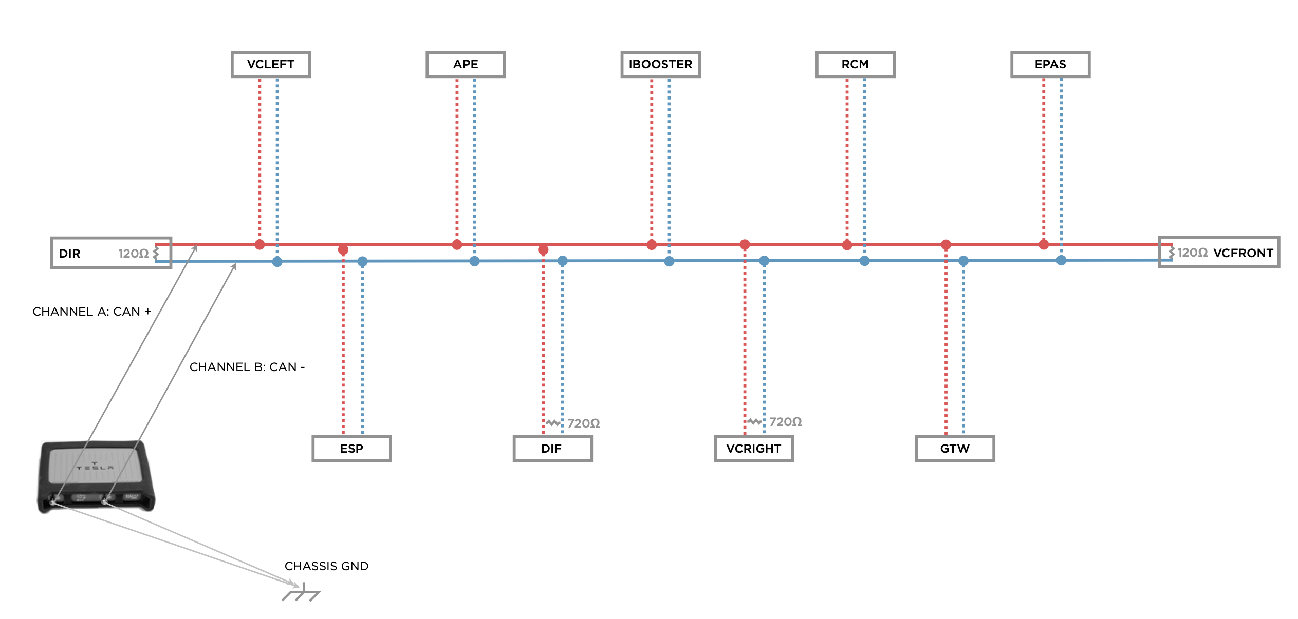
Measuring Network Resistance
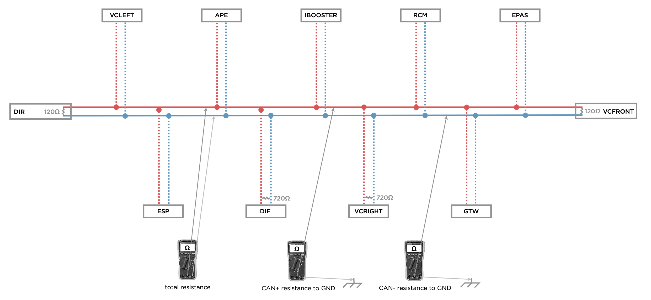
- Power down the vehicle.
- Measure the "total resistance" of the CAN network. This should be close to 60 Ω.
- If total resistance equals 120 Ω, then there is an open circuit in one part of the circuit.
- If total resistance is less than 60 Ω, then there is most likely a short in the circuit from CAN+ to CAN- or to another circuit.
- Measure "CAN+ resistance to GND" to determine if there is a short to chassis ground.
- Measure "CAN- resistance to GND" to determine if there is a short to chassis ground.
×
![]()