Steeringlink
Last updated: August 12, 2024
Overviewlink
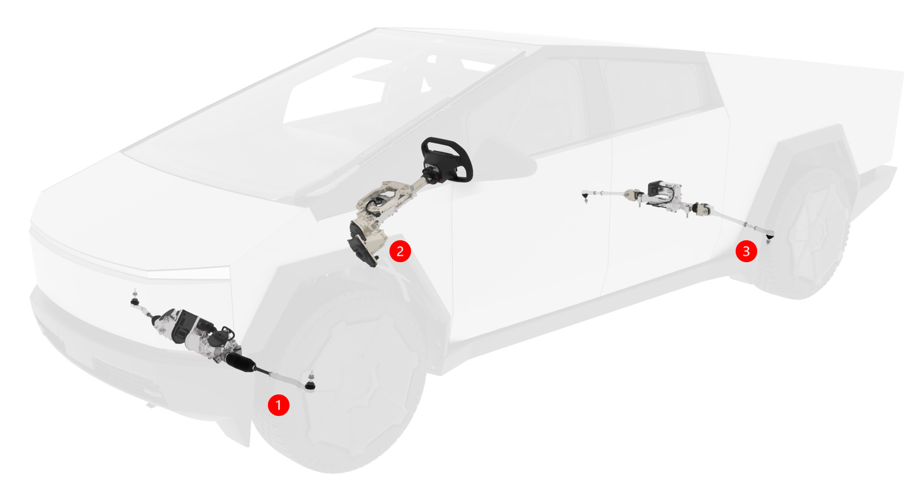
Cybertruck features a Steer-by-Wire (SbW) system that eliminates the intermediate shaft used to steer in traditional automotive designs. There is no mechanical linkage between the steering wheel and road wheels.
 |
|---|
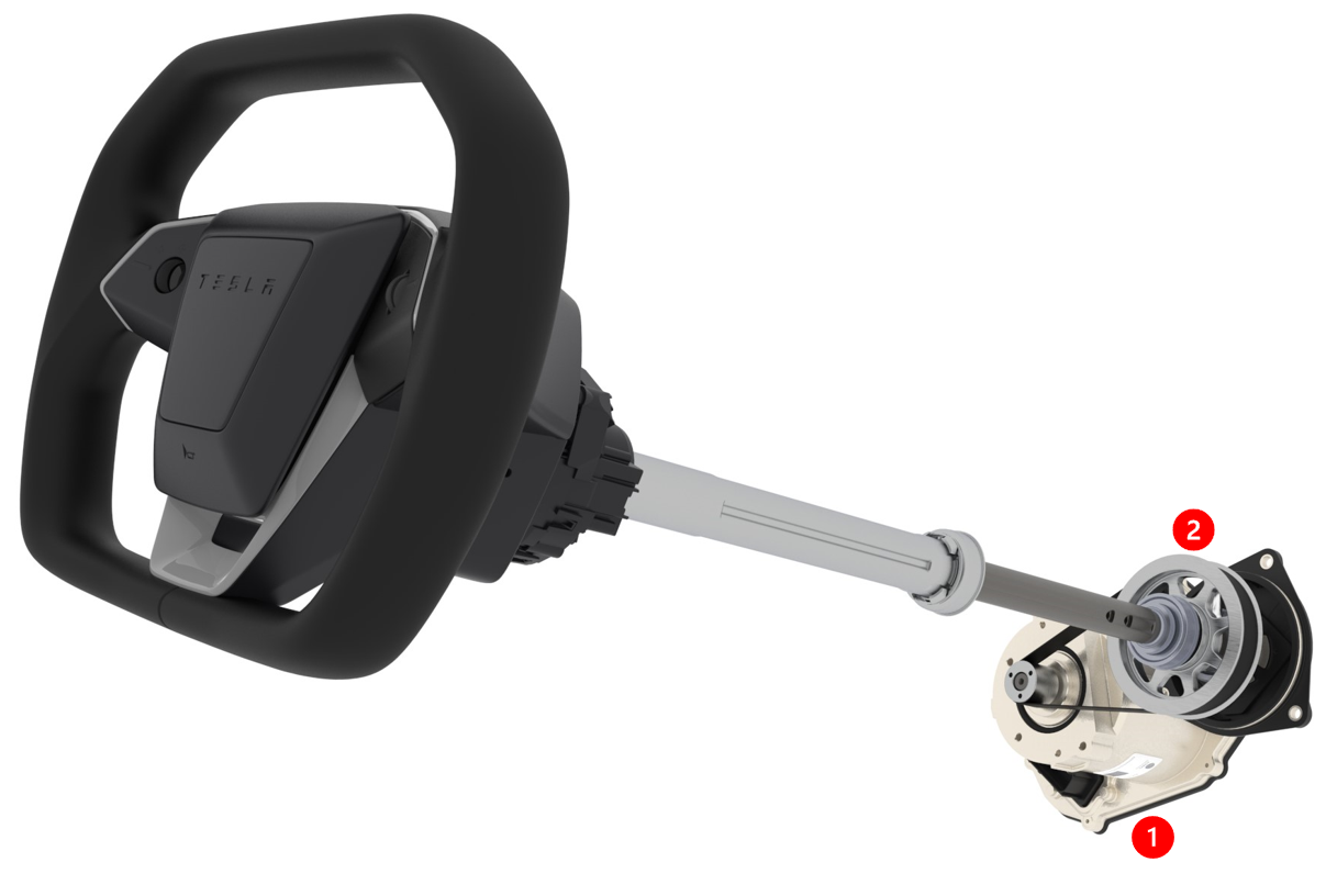
| 1. Steering Feedback Actuator 2. Steering Column Assembly 3. Rear Steering Actuator |
| Steer-by-Wire Overview |
The road wheels are controlled by a series of electro-mechanical controllers, actuators, and angle sensors. The steering wheel mounts to the steering column with the steering column control module located between. At the opposite end of the steering column is a torque feedback actuator which measures the handwheel angle and provides torque feedback while driving. The steering rack is mounted to the front subframe and two motors work simultaneously to provide torque to the rack. The steering rack and steering feedback actuator communicate their angles to each other, this is used by the primary feedback controller to decide how much torque and angle to command the front and rear steering racks to. Normal operation is monitored by a redundant set of controllers to ensure the system can continue operating under normal driving control flow. The system has fully redundant power and communication.
 |
|---|
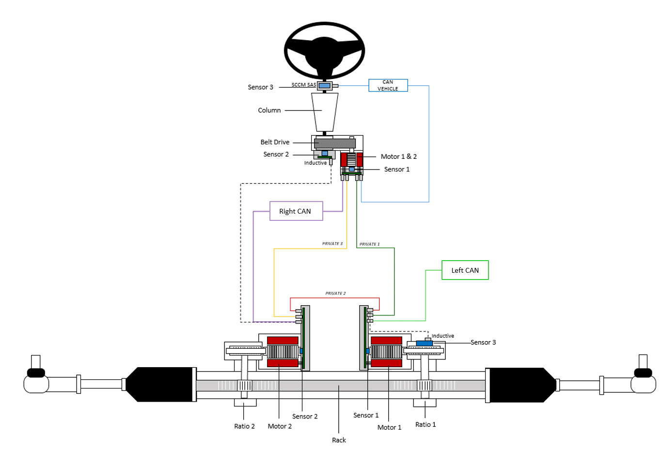
| System Diagram |
Steering Wheellink
 |
|---|
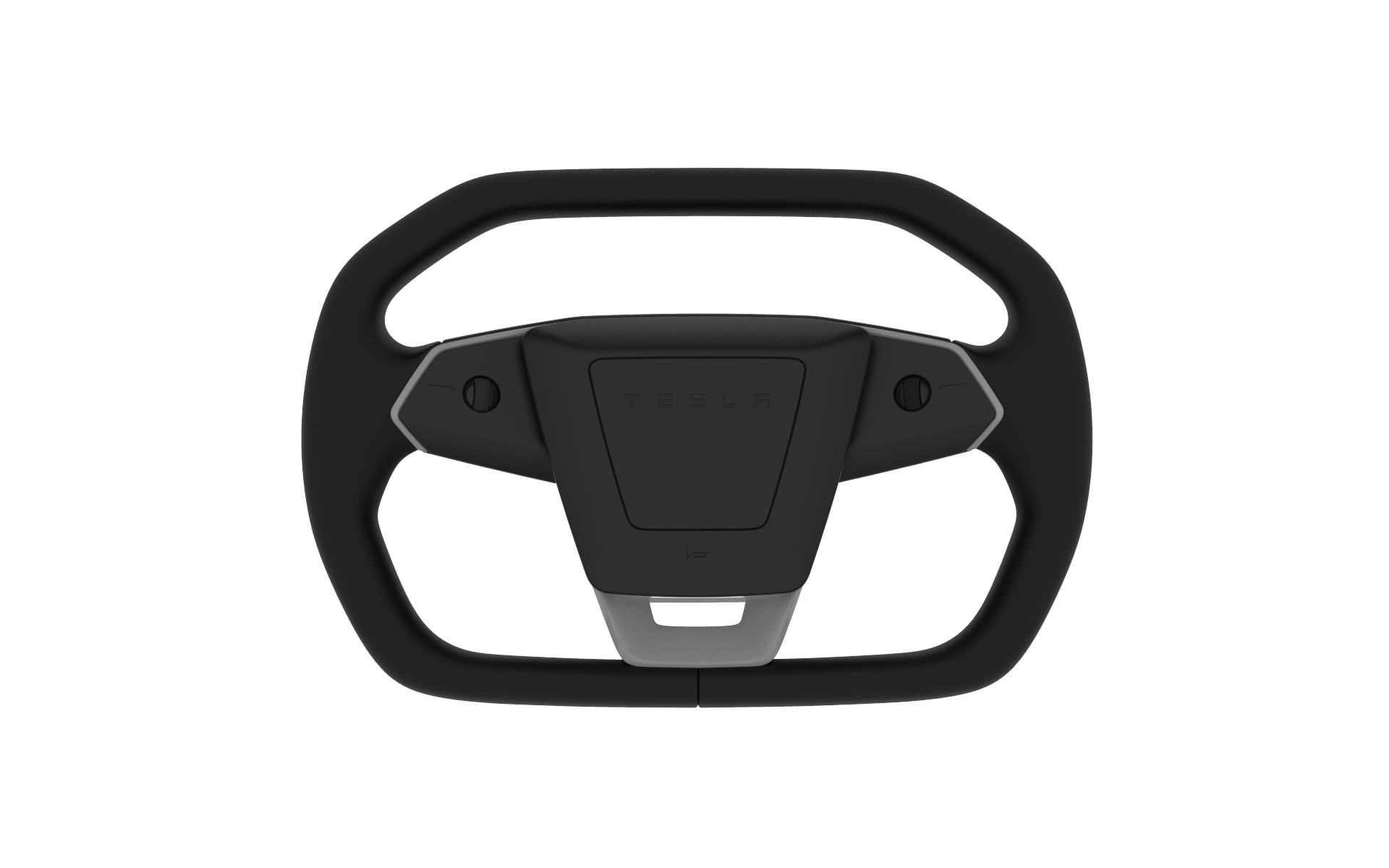
| Steering Wheel |
The steering wheel is positioned in front of the driver and is mounted to the steering column. The steering wheel is home to the steering wheel switches and scroll buttons that are mechanically actuated. This allows the driver to control multiple actions from the steering wheel. The steering wheel switches and buttons communicate with the left vehicle controller over Local Interconnect Network (LIN) bus.
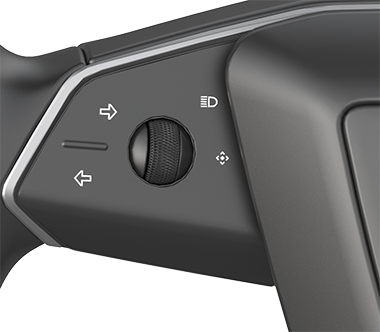
The left switches contain left and right turn signals, high beam headlights, the left scroll wheel (for volume, phone calls, custom feature, steering column and mirror adjustments) and an indicator to represent if the left scroll wheel button custom feature is enabled.
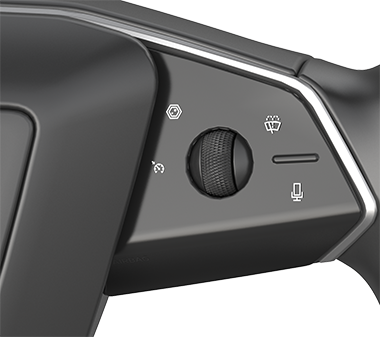
The right switches control the camera views, windshield wipers, voice commands and right scroll wheel button (for Autopilot features). There is also the cruise control indicator.
 |
|---|
| Left Steering Wheel Switches |
 |
|---|
| Right Steering Wheel Switches |
The steering wheel is the bracket for the driver airbag. When the airbag is pressed it activates the horn. The steering wheel is a circular design with flat edges on the top and bottom. It has heating capability and is made of molded rubber and Polyurethane. The steering wheel is installed onto the steering column with indexed splines that make sure they are both in the correct orientation. The maximum angle the steering wheel can be rotated in one direction mechanically limited to ~170 degrees. The steering ratio of the handwheel and road wheel dynamically changes while driving.
 |
|---|
| Low Speed Steering |
 |
|---|
| High Speed Steering |
Serviceabilitylink
The steering wheel, switch packs and the driver airbag (DAB) are fully replaceable. The switch packs and DAB are not internally serviceable.
Steering Column Control Module (SCCM)link
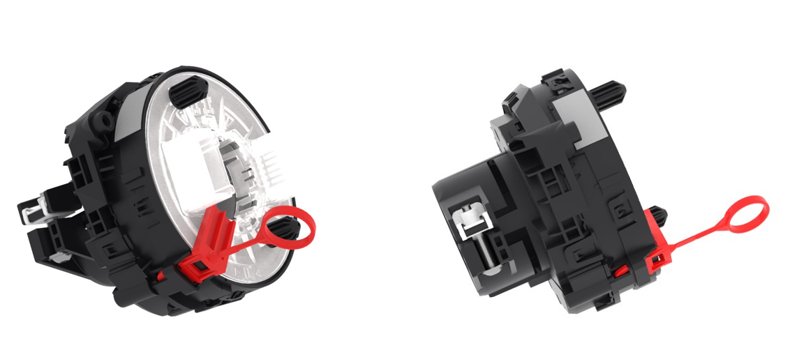
The Steering Column Control Module (SCCM) is located behind the steering wheel on the steering column. It has a clip that fastens into a square hole in the column. A plastic clamp fastens the SCCM onto the column.
 |
|---|
| Steering Column Control Module |
The SCCM features a steering angle sensor, and a clock spring that pass through LIN communication and power to driver airbag, the steering wheel controls, and heater mat. As the steering wheel rotates the SCCM, the clock spring maintains electrical continuity for the pass-through connections. The SCCM angle sensor and steering wheel are powered by and communicate with the Left Vehicle Controller (VCLEFT). The steering column ships from the supplier with a delivery lock pin to prevent clock spring damage by over rotation, it is removed before the steering wheel is installed.
Steering Columnlink
The steering column is comprised of a steering input shaft, base plate, pivoting brackets, sliding carrier, motors for pitch and longitudinal adjustment, torque feedback actuator, and a gearbox. The aluminum base plate is used to mount the column assembly to the Instrument Panel (IP).
 |
|---|
| Steering Column Assembly (exploded-view) |
Steering Feedback Actuatorlink
When the driver moves the steering wheel it moves the steering column shaft, providing torque to a belt driven gearbox. As the gearbox moves it rotates the torque feedback actuator. The feedback actuator has a controller used to measure the angle of rotation, and it can provide torque back to the driver. The Feedback Actuator produces motor torque through a power redundant double wound motor.
 |
|---|
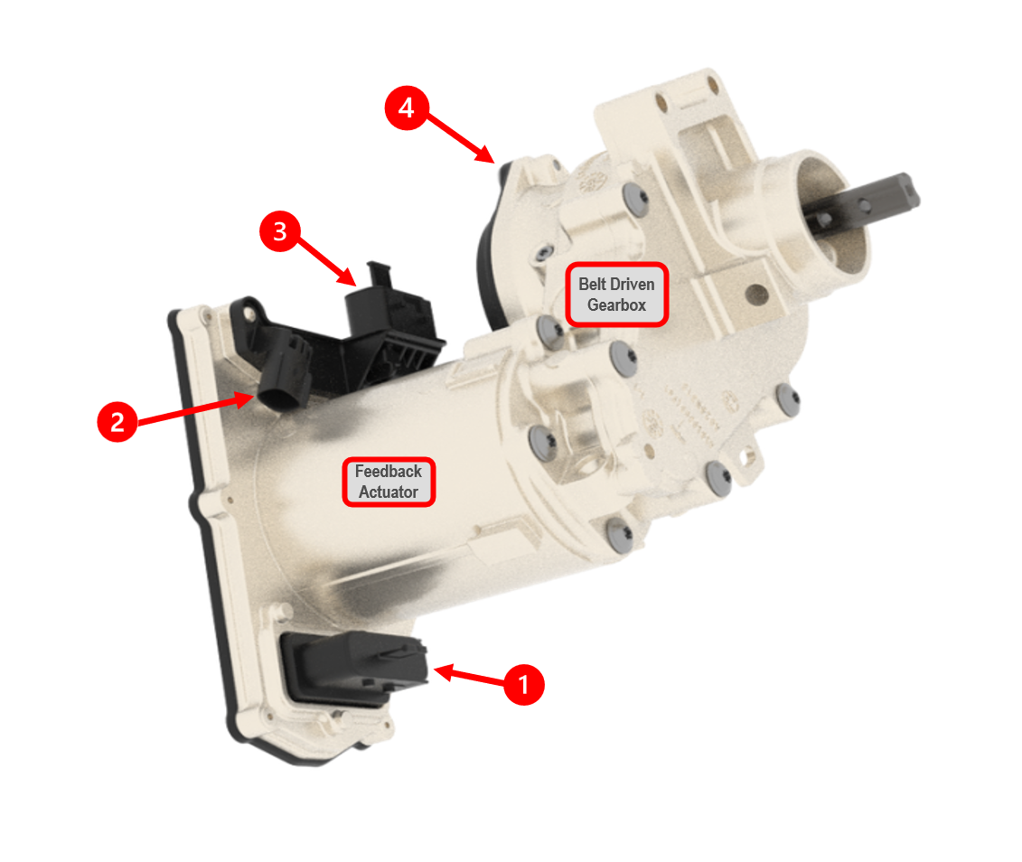
| 1. Steering Feedback Actuator 2. Belt Driven Gearbox (internal view) |
| Steering Feedback Actuator (column assembly hidden) |
There are four controllers that are power and communication redundant:
| Controller | Description | Acronym | Power Source |
|---|---|---|---|
| Primary Steering Feedback Actuator | Inverter used for torque production | PSFA | VCLEFT |
| Primary Steering Feedback Actuator Monitor | Monitor used to disable torque production | PSFAM | VCLEFT |
| Secondary Steering Feedback Actuator | Inverter used for torque production | SSFA | VCRIGHT |
| Secondary Steering Feedback Actuator Monitor | Monitor used to disable torque production | SSFAM | VCRIGHT |
The Primary Steering Feedback Actuator Monitor (PSFAM) and the Secondary Steering Feedback Actuator (SSFAM) are capable of disabling motor torque when they detect an issue with the vehicle that would subject the steering system to unsafe driving conditions requiring a graceful pull over. The PSFA and SSFA controllers are the inverters used for torque production and have individual motor position sensors that are used to measure the angle of rotation.
 |
|---|
| 1. Primary Power, Public and Private Communication (X0436) 2. Secondary Private CAN (X0435) 3. Secondary Power Connection (X0437) 4. Handwheel Angle Sensor (X0432) |
| Steering Feedback Actuator |
Handwheel Angle Sensorlink
There is a separate backup handwheel angle sensor (HAS) mounted onto the belt driven gearbox. The sensor measures the handwheel angle as a backup to the primary feedback actuator angle sensor. The handwheel angle sensor has a private CAN (SENT) communication with the secondary electronic power steering ECU (SEPS) on the steering rack.
Serviceabilitylink
During the handwheel calibration routine, PSFA and SSFA learn the end stops to determine the center handwheel position. The secondary electronic power steering ECU (SEPS) on the steering rack is also calibrating handwheel center using the handwheel angle sensor (HAS). This is because SEPS is a used to command front rack angle when SFA faults.
The steering column assembly is replaceable but not internally serviceable. The Steering Feedback Actuator (SFA) is also replaceable but not internally serviceable. If the SFA is replaced, the steering wheel must be centered and the following action must be run to learn the new center position: PROC_X_SBW-FACTORY-COMMISSION.
Warning
The power pack must never be loosened from the gearbox otherwise the belt in the gearbox will lose tension. If this happens it is necessary to replace the feedback actuator (power pack + gearbox). Also note that when replacing the SFA + gearbox take precautions to not allow the steering wheel to rotate as this will cause damage to the SCCM clockspring and require it to be replaced.
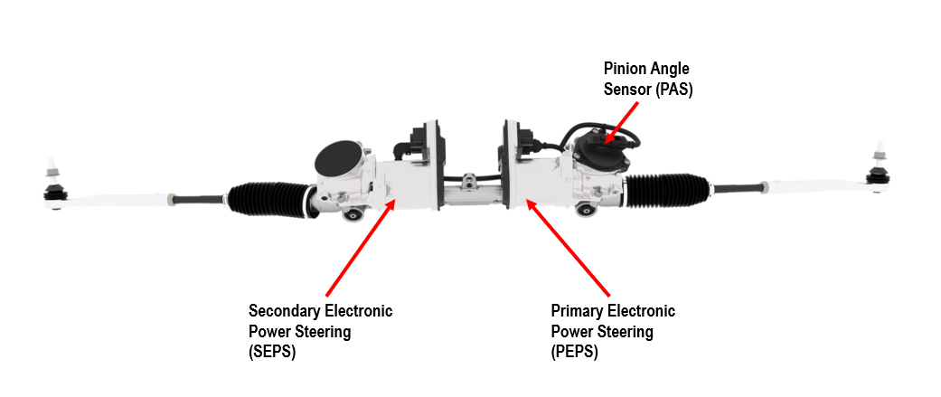
Front Electronic Power Steering Gearlink
The front steering gear is a rack and dual pinion design. It is secured to the front subframe with two rubber bushing mounts and two fasteners. There are two actuators and four controllers on the front steering gear. Both actuators feature their own single wound motor, one controller inverter for producing motor torque, and one monitor ECU capable of disabling motor torque. If one motor shorts, the other motor will provide sufficient torque to pull the vehicle over.
 |
|---|
| Steer-by-Wire Front Steering Gear |
| Controller | Description | Acronym | Power Source |
|---|---|---|---|
| Primary Electric Power Steering | inverter used for torque production | PEPS | VCLEFT |
| Primary Electric Power Steering Monitor | monitor used to disable torque production | PEPSM | VCLEFT |
| Secondary Electric Power Steering | inverter used for torque production | SEPS | VCRIGHT |
| Secondary Electric Power Steering Monitor | monitor used to disable torque production | SEPSM | VCRIGHT |
Both of the actuators operate simultaneously. The torque is delivered to the gearboxes which turn the pinion gears and result in lateral motion of the rack bar. When the rack bar moves laterally, the tie rods that connect the rack bar to the front knuckles will follow the same path and move the front road wheels left and right.
 |
|---|
| Steer-by-Wire Front Steering Gear |
Electrical Connectionslink
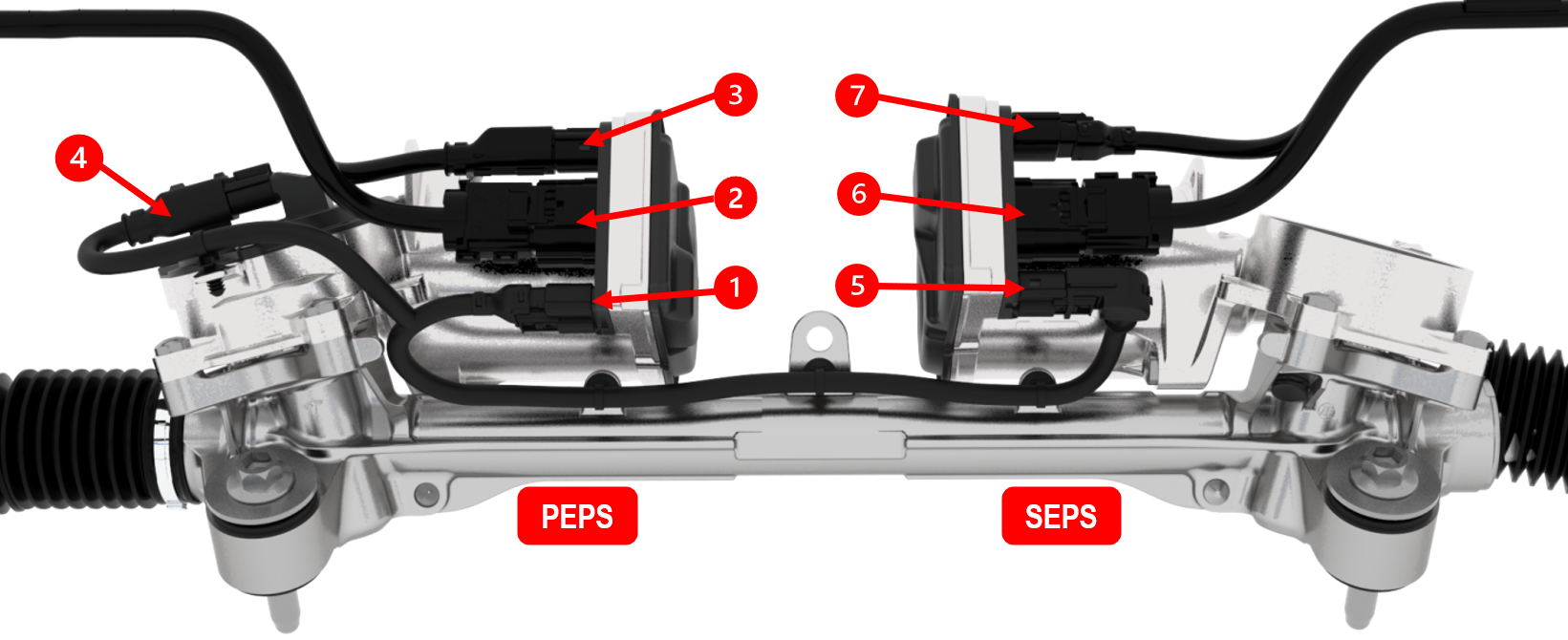 |
|---|
| 1. PEPS RACK CAN - (Private) - X0441 2. PEPS LEFT CAN (Public) and PEPS Power - X0442 3. PEPS SHAFT CAN P (Private) - X0440 4. Pinion Angle Sensor (SENT) and Pinion Angle Sensor Power - X0443 5. SEPS RACK CAN - (Private) - X0446 6. SEPS RIGHT CAN (Public) and SEPS Power - X0437 7. SEPS SHAFT CAN S (Private) - X0432 |
| Front Steering Gear Connections and BUS Names |
Pinion Angle Sensorlink
There is a steering rack pinion angle sensor (PAS) mounted onto the primary steering actuator gearbox. The sensor measures rack position and reports directly to PEPS via SENT communication.
Front Steering Gear Serviceabilitylink
The front steering gear is individually replaceable, and can be removed from the vehicle laterally without removing the front subframe. The harness that comes with the steering gear is replaceable. The primary and secondary electronic power packs are both replaceable, however they require a metal piece inside the gearbox to be replaced, called the plunger.
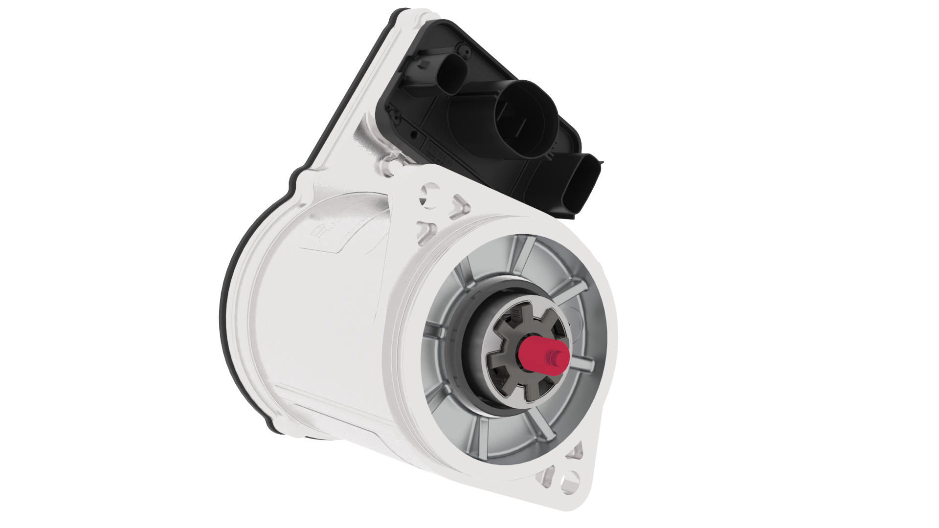 |
|---|
| Plunger Interface Location With EPS |
The plunger must be sized correctly based on the length between the interface of the power pack and gearbox. The length of the gearbox and length of the electric power steering module are stored in the QR code on the part label that comes with the parts, this can be decoded with a 2D barcode scanner. Should the label become illegible, it is recommended to replace the steering rack. If incorrectly sized, the wrong plunger used could result in an NVH complaint from the customer, reduced lifespan of the part, or it could result in a VOR for position detection failure. The O-ring that seals the EPS and gearbox from water ingress must be replaced along with new grease applied at this location. Take extreme caution to perform this repair correctly, always refer to the service manual for the proper steps to follow.
The tie rods are fully replaceable. The outer tie rod is replaced by loosening it from the inner tie rod. If the inner tie rod requires replacement, it is recommended to replace the front steering gear.
Rear Electronic Power Steering Gearlink
The rear steering gear improves steering performance while driving and reduces the turning radius at low vehicle speeds. The rear steering gear mounts to the rear subframe with four fasteners.
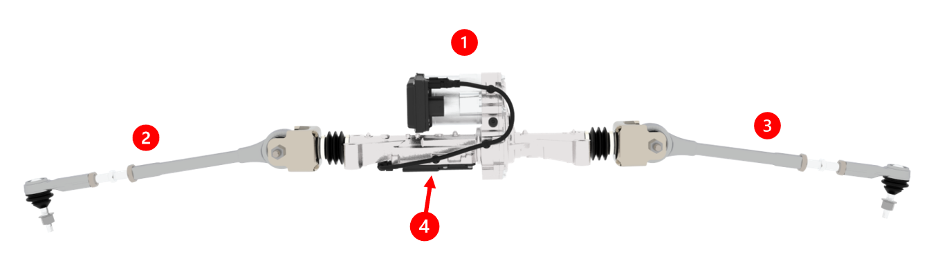 |
|---|
| 1. Rear Steering Actuator (RSA) 2. Tie Rod 3. Tie Rod 4. Linear Position Sensor (LPS) |
| Rear Steering Gear |
The rear steering gear features a planetary roller gear and a tie rod on each side of the vehicle that connects to the rear knuckles. There is an electronic power pack on the rear steering gear comprised of one motor winding, one Electronic Control Unit (ECU) inverter capable of inverting DC to AC current to produce motor torque, and one monitor ECU capable of stopping motor torque.
The rear steering gear comes from the supplier with a private harness used by the rear steering actuator (RSA) to power and communicate with a linear rack position sensor via SENT communication. When the power pack motor rotates, it transfers torque to the belt-driven planetary roller mechanism which translates to lateral rack bar movement. When the rack bar moves side to side laterally, this moves the tie rods the same direction and articulates the rear road wheels to a maximum of ~8.8 degrees on each side at full steering wheel lock at standstill.
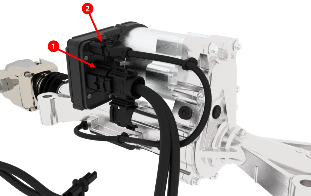 |
|---|
| 1. RSA REARSTEER CAN (Public) and Power - X0423 2. Linear Position Sensor Power and SENT communication |
| Rear Steering Gear Electrical Connections and BUS Name |
Note
The rear steering rack cannot be back-driven by manually moving the rear road wheel.
Rear Steering Rack Serviceabilitylink
The rear steering gear is fully replaceable. It can be removed through the bed with the bed access panel removed. The tie rod ends are fully replaceable. The SENT harness is individually replaceable. The motor should never be removed from the belt driven gearbox as this will cause the belt to lose tension.
Wheel Alignmentlink
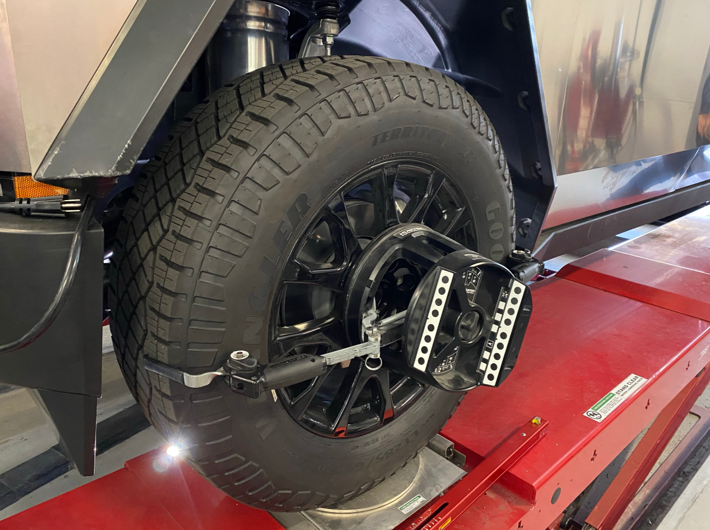
The Cybertruck is aligned by adjusting the front and rear toe angles only. There are no camber or caster adjustments. The air suspension ride height setting during wheel alignment is medium height. Tire pressures must be checked prior to alignment.
 |
|---|
| Wheel Alignment |
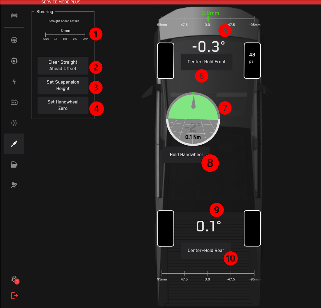
The front and rear steering gears must be at their mechanical center during toe link adjustments, and if they are not centered, then the vehicle will not drive straight. There are 3 hold routines available on the alignment panel in service mode plus which allows the user to center the front rack, rear rack, and steering wheel. Note that the steering wheel does not need to be held centered during alignment for Cybertruck; only the front and rear racks must be. The steering wheel hold routine is useful for checking where the truck thinks 0 deg steering wheel angle is looks physically centered to the driver. The visual references used to assess steering wheel calibration are the top flat edge of the steering wheel and the lightbar behind the steering wheel, they must look parallel otherwise it is necessary to perform a steering wheel center calibration (also available on the alignment panel).
The straight ahead detection must be cleared before adjusting the wheel alignment. Straight ahead detection is the lateral offset the rack needs to be positioned in order to get the truck to drive straight, based on yaw rate. This is learned quickly by the vehicle after it is first built or after alignment, while it is driving straight. When the steering wheel is centered, the steering rack will be physically positioned at the straight ahead offset, not the center of the rack based on end stop calibration.
The front steering gear tie rods feature jam nuts to tighten or loosen the inner tie rod to the outer tie rod. The inner tie rod should be used to adjust the toe angle. Both of the rear toe links feature two jam nuts for a total of four. To adjust the rear toe angle, the inner turnbuckle between the two loose jam nuts can be rotated in a clockwise or counterclockwise direction to adjust the toe angle.
The front steering gear, rear steering gear, and the SFA are calibrated for their center positions based on the mechanical end stop locations. To measure the caster angle, disable the rear steering actuator on the alignment panel using the RSA hold routine, this will prevent the rear steering actuator moving during the front lock to lock maneuver.
 |
|---|
| 1. Indicates Current Straight Ahead Offset 2. Clears Straight Ahead Offset 3. Air Suspension Leveling Commands 4. Calibrates the Handwheel Center 5. Front Rack Position (Top) and Road Wheel Angle (Bottom) 6. Hold Front Rack Center 7. Indicates Steering Wheel Angle (PSFA_handwheelrotation) 8. Holds Steering Wheel Center 9. Rear Road Wheel Angle (Top) and Rear Rack Position (Bottom Slider) 10. Holds and Disables Rear Steering Actuator |
| Service Mode - Alignment Panel Actions |
Steering Theory of Operationlink
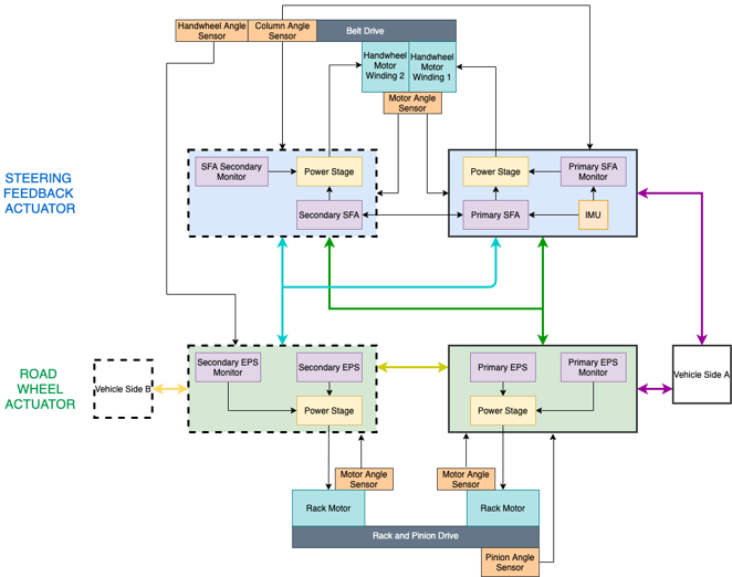
The driver rotates the steering wheel clockwise or counterclockwise. As the steering wheel rotates, the clock spring and steering column rotate with it because they are mechanically assembled together. The steering angle sensor in the steering column control module measures the steering wheel angle along with three other redundant steering wheel angle sensors in the Steering Feedback Actuator (SFA). There are two steering angle sensors using the motor position sensors of the primary and secondary feedback actuators. The third angle sensor is the handwheel angle sensor on the feedback actuator gearbox between the actuator and the steering column.
 |
|---|
| Block Diagram |
Steering Control Flowlink
The Primary Steering Feedback Actuator (PSFA) is the main controller which commands motor torque and angle to the front and rear steering gears. When there is an issue affecting the primary steering feedback actuator, the system is redundant and will utilize inputs from the Secondary Steering Feedback Actuator (SSFA) controller. If the Steering Feedback Actuator suffers a major fault, the secondary electronic power steering (SEPS) ECU is used as a backup handwheel angle sensor from the sent angle provided by the handwheel angle sensor on the steering column. In this case, RSA would center itself and disable and SEPS would provide torque command only to the front steering gear (PEPS and SEPS).
At standstill, a full steering wheel lock is 170 degrees from center and moves the front road wheels ~34 degrees, the rear wheels ~8.8 degrees.
| Vehicle Power State | Steering Wheel Behavior | Steering Rack Behavior |
|---|---|---|
| Drive | The driver can move the steering wheel and feel normal torque feedback while driving | The front and rear steering racks will move based on the steering wheel input |
| Accessory | The steering wheel will hold the last position from exiting drive state. This allows occupants to use the steering wheel for support during vehicle entry and exit. | The steering rack will hold the last position from exiting drive state |
| Off | The steering wheel can freely move with no torque feedback | The steering racks will hold the last position from exiting accessory state |
Note
If the steering wheel moves while the vehicle is OFF, the next time it enters accessory power state the steering wheel will return to the position of the steering rack. If the front road wheels are moved while the vehicle is off, the next time it enters accessory power state the steering wheel will move to that position.
The road wheel angle commanded to the front steering gear triggers the Primary Electronic Power Steering (PEPS) and Secondary Electronic Power Steering (SEPS) motor controllers to produce torque through the motor, rotating the worm wheel and gear, outputting torque onto the rack bar in the direction the rack needs the motors to spin to reach the target rack angle. The same happens for the rear, except the torque produced by the motor spins the output shaft and belt in the direction the planetary roller gear needs to rotate for translating the rack laterally until the rack reaches the target angle commanded.
Note
For some system faults, the vehicle may attempt to automatically center the rear steering rack.
When driving at low speeds, the front and rear road wheels turn inversely, and at higher speeds, they turn the same direction. When the vehicle is parked and the driver door opens and occupants exit the vehicle, the steering wheel and road wheels lock their current position. When the user returns to the vehicle, the steering wheel remains locked until the driver presses the brake pedal. At that time, the hold will release, and the driver can steer in the desired direction.
The steering ratio at standstill is ~34 degrees at the front road wheels when the steering wheel is at full lock (~170 degrees). At full lock, the rear road wheels reach a maximum of ~8.8 degrees. The rear wheels will turn the opposite direction at standstill. Under acceleration, the rear wheels transition to turning in same direction as the front, and the turning ratio changes dynamically. At low speeds, the rear steering turns the opposite direction of the front steering to decrease overall turning radius. At high speeds, the rear steering improves stability yaw rate control around the z-axis.
The two basic parameters that dictate the open loop model for the dynamic steering ratio are:
- Vehicle speed: The ratio between the handwheel angle and steering wheel angle changes with vehicle speed. At standstill, it has the quickest turning ratio of 5:1 and as speed increases, the ratio gets slower.
- Handwheel angle: The basic principal is to slow down yaw rate gain on center, and speed it up off center. This results in a snappier steering response when the handwheel angle is higher. Frequency domain is another tunable ratio used for vehicle dynamics; however, for the purpose of understanding the basic dynamic steering ratio parameters, this is as far as theory of ops will cover for steering tune.
Steering Redundancy and Recoverylink
The Cybertruck Steer-by-Wire system is redundant for power and communication. Steer-by-Wire is controlled by several redundant sensors and controllers that are split between 2 different power domains. The power domains are separate power distribution networks designed so that if one side loses power, the other side will maintain power and communication to the other set of redundant controllers needed to continue steering. In the event of loss of 1 power domain, or any steering controller that loses 1 form of redundancy, the vehicle notifies the driver to pull over and the steering cluster UI alerts will be shown to the user. During the normal primary steering control flow, the primary steering feedback actuator is responsible for sending the front and rear road wheel angle commands for steering. The primary angle sensor used is the angle sensor on the primary side of the steering feedback actuator PCB. When the primary steering control faults and loses redundancy, it will fall back on the secondary control flow where the road wheel angle is commanded by the secondary electronic power steering (SEPS) controller on the front rack. The SEPS controller is able to read the handwheel angle directly from the dedicated hand wheel angle sensor. The rear rack will also disable and center itself when reverting to secondary control flow.
For more information on the left and right power domains, see the Controllers and Wiring section.
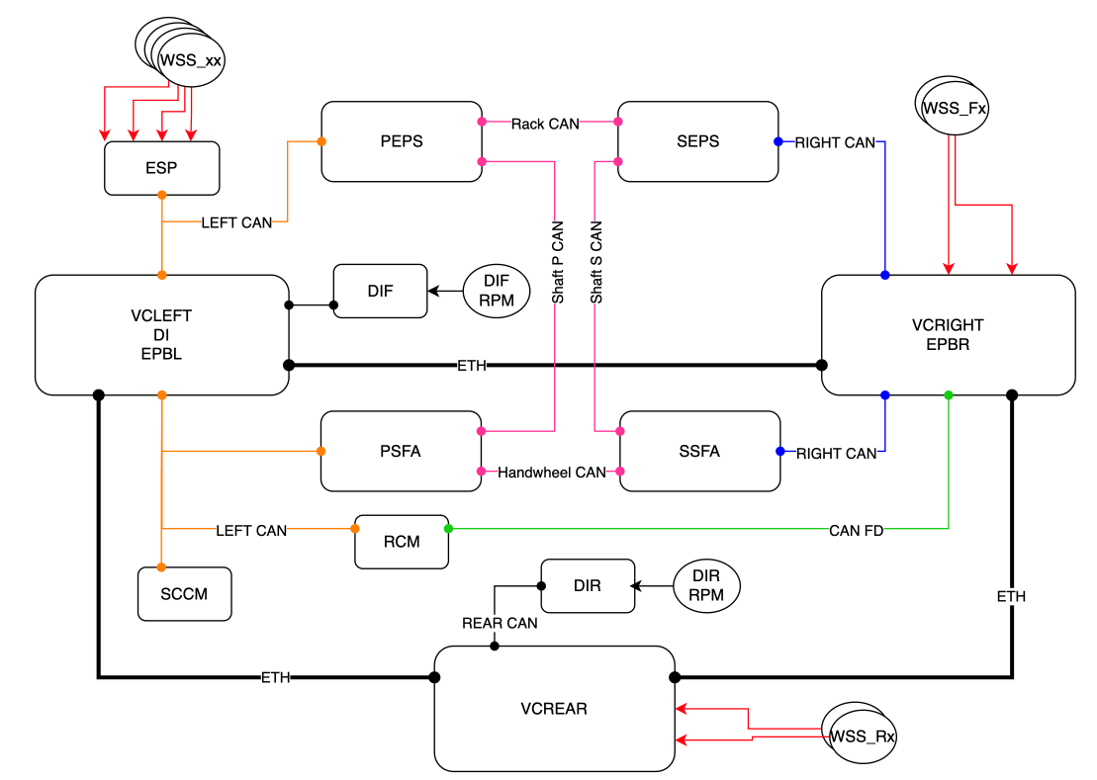
CAN Architecturelink
 |
|---|
| Steer-by-Wire Communication Architecture |
There are 6 main Controller Area Network (CAN) buses used by the Steer-by-Wire (SbW) system during normal operation (there are several more internal Buses that will not be covered in theory of operation, the focus should be on learning these below):
- Left CAN (LC)
- Right CAN (RC)
- Shaft Primary (SHAFTP)
- Shaft Secondary (SHAFTS)
- RACK
- REARSTEER
Steering Alertslink
Steer-by-wire alerts indicate the following: steering angle errors, version mismatches, input resistance issues, Steering Column Control Module (SCCM) runtime errors, eFuse trips, wiring shorts, communication issues, thermal overheating, monitor trips, voltage errors, irrational input from controller, controller timeouts, or degraded rear steering. Some of the alerts may present due to underlying electrical issues. For more information on diagnosing the Mid-Voltage system, see the Wiring and Controllers section. If the same alerts keep setting over many power cycles, then this is may be due to a hardware issue and part replacement may resolve the issue. If the alert sets and clears after a power cycle and never returns, then part replacement is likely unnecessary. Some alerts may indicate issues that can be resolved using a firmware redeploy or full package firmware flash.
Steering Signalslink
The following table shows useful signals that aid diagnosis and repair of the Steer-by-Wire (SbW) system. These signals may change as the firmware develops. These are the categories of signals used: Steering angle diagnostics, power and health statuses, and calibration state.
| signal | Signal Type | Description |
|---|---|---|
| EGGLEFTVC_steeringColumnInOutPos | Steering column diagnostic | Monitor steering column position; Changes on the order of tens of seconds |
| EGGLEFTVC_steeringColumnSMState | Steering column diagnostic | Monitor steering column state machine state; Changes quickly |
| EGGLEFTVC_steeringColumnUpDownPos | Steering column diagnostic | Monitor steering column position; Changes on the order of tens of seconds |
| PSFA_rearSteeringAngleRequest | Steering Angle Diagnostic | Shows rear steering angle request from primary steering feedback actuator; Could change quickly during normal operation |
| RSA_rearRoadwheelAngle | Steering Angle Diagnostic | Shows rear steering angle from rear steer actuator; Could change quickly during normal operation |
| SEPS_handwheelRotationLogging | Steering Angle Diagnostic | Shows current measured backup hand wheel position. Left turn positive; Could change quickly during normal operation |
| PEPS_rackPosition | Steering Angle Diagnostic | Shows current measured rack position. Left turn positive; Could change quickly during normal operation |
| PEPS_roadwheelAngle | Steering Angle Diagnostic | Average front road wheel angle measured by EPS.; High frequency needed for vehicle behavior analysis |
| SEPS_steeringAngleRequest | Steering Angle Diagnostic | Shows backup steering angle request from secondary rack actuator; Could change quickly during normal operation |
| SEPS_rackPosition | Steering Angle Diagnostic | Shows current measured rack position. Left turn positive; Could change quickly during normal operation |
| SEPS_roadwheelAngle | Steering Angle Diagnostic | Average front road wheel angle measured by EPS.; High frequency needed for vehicle behavior analysis |
| SEPS_roadwheelAngleQF | Steering Angle Diagnostic | Shows road wheel angle health; Could change quickly during normal operation |
| PSFA_driverInputTorque | Steering Angle Diagnostic | Steering Wheel Torque Input from Driver.; High frequency needed for driver input and vehicle behavior analysis |
| PSFA_handwheelRotation | Steering Angle Diagnostic | Shows current measured hand wheel position. Left turn positive; Could change quickly during normal operation |
| PSFA_steeringAngleRequest | Steering Angle Diagnostic | Shows steering angle request from primary steering feedback actuator; Could change quickly during normal operation |
| SSFA_handwheelRotation | Steering Angle Diagnostic | Shows current measured hand wheel position. Left turn positive; Could change quickly during normal operation |
| RSA_dcBusCurrent | Power | Shows DC current motor is drawing from the vehicle LV system; Could change quickly during normal operation |
| RSA_dcBusVoltage | Power | Shows DC bus voltage measured by motor controls; Could change quickly during normal operation |
| PEPS_dcBusCurrent | Power | Shows DC current motor is drawing from the vehicle LV system; Could change quickly during normal operation |
| PEPS_dcBusVoltage | Power | Shows DC bus voltage measured by motor controls; Could change quickly during normal operation |
| PSFA_dcBusCurrent | power | Shows DC current motor is drawing from the vehicle LV system; Could change quickly during normal operation |
| PSFA_dcBusVoltage | power | Shows DC bus voltage measured by motor controls; Could change quickly during normal operation |
| SSFA_dcBusCurrent | power | Shows DC current motor is drawing from the vehicle LV system; Could change quickly during normal operation |
| SSFA_dcBusVoltage | power | Shows DC bus voltage measured by motor controls; Could change quickly during normal operation |
| RSA_stateMachine | Health Status | Shows current state of the rack controller state machine; Could change quickly during normal operation |
| RSA_rearRoadwheelAngleQF | Health Status | Shows rear steering angle QF from rear steer actuator |
| PEPS_rackHealth | Health Status | Rack subsystem health is critical for fault analysis.; High frequency needed for vehicle behavior analysis |
| PEPS_roadwheelAngleQF | Health Status | Shows road wheel angle health; Could change quickly during normal operation |
| PEPS_steeringStatusForDrive | Health Status | Shows steering status for drive; Could change quickly during normal operation |
| PEPS_handwheelControlFlowCCW | Health Status | Shows current hand wheel control flow; Could change quickly during normal operation |
| PEPS_roadwheelControlFlowCCW | Health Status | Shows current road wheel control flow; Could change quickly during normal operation |
| PEPS_systemStateCCW | Health Status | Shows current state of ECU; Could change quickly during normal operation |
| SEPS_handwheelHealth | Health Status | Shows SBW handwheel calibration |
| SEPS_rackHealth | Health Status | Rack subsystem health is critical for fault analysis.; High frequency needed for vehicle behavior analysis |
| SEPS_rackMechState | Health Status | Shows current state of rack position detection |
| SEPS_steeringStatusForDrive | Health Status | Shows steering status for drive; Could change quickly during normal operation |
| SEPS_handwheelControlFlowCW | Health Status | Shows current hand wheel control flow; Could change quickly during normal operation |
| SEPS_roadwheelControlFlowCW | Health Status | Shows current road wheel control flow; Could change quickly during normal operation |
| SEPS_systemStateCW | Health Status | Shows current state of ECU; Could change quickly during normal operation |
| PSFA_handwheelHealth | Health Status | Shows SBW handwheel calibration |
| PSFA_steeringStatusForDrive | Health Status | Shows steering status for drive; Could change quickly during normal operation |
| PSFA_handwheelRotationQF | Health Status | Shows current measured hand wheel position. Left turn positive; Could change quickly during normal operation |
| PSFA_handwheelControlFlowCW | Health Status | Shows current hand wheel control flow; Could change quickly during normal operation |
| PSFA_roadwheelControlFlowCW | Health Status | Shows current road wheel control flow; Could change quickly during normal operation |
| PSFA_systemStateCW | Health Status | Shows current state of ECU; Could change quickly during normal operation |
| SSFA_handwheelRotationQF | Health Status | Shows current measured hand wheel position. Left turn positive; Could change quickly during normal operation |
| SSFA_handwheelHealth | Health Status | Shows SBW handwheel calibration |
| SSFA_steeringStatusForDrive | Health Status | Shows steering status for drive; Could change quickly during normal operation |
| SSFA_handwheelControlFlowCCW | Health Status | Shows current hand wheel control flow; Could change quickly during normal operation |
| PEPS_rackCalibrated | Calibration | Collect data on calibration change over time |
| SEPS_handwheelCalibrated | Calibration | Shows status of SBW handwheel calibration |
| SEPS_rackCalibrated | Calibration | Collect data on calibration change over time |
| SEPS_sccmCalibrated | Calibration | Shows status of SBW handwheel calibration |
| SEPS_sccmZeroOffset | Calibration | Shows SBW handwheel calibration |
| PSFA_handwheelCalibrated | Calibration | Shows status of SBW handwheel calibration |
| PSFA_handwheelEndStopsCalibrated | Calibration | Shows status of SBW handwheel calibration |
| PSFA_sccmCalibrated | Calibration | Shows status of SBW handwheel calibration |
| PSFA_sccmZeroOffset | Calibration | Shows SBW handwheel calibration |
| SSFA_handwheelCalibrated | Calibration | Shows status of SBW handwheel calibration |
| SSFA_sccmCalibrated | Calibration | Shows status of SBW handwheel calibration |
| SSFA_sccmZeroOffset | Calibration | Shows SBW handwheel calibration |