Autopilot Hardware 4.0link
Last updated: December 17, 2024
Introduction and Overviewlink
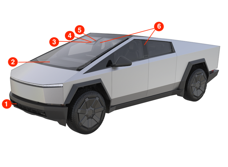
Cybertruck vehicles are equipped with Driver Assistance hardware generation 4 (HW4) components.
Tip
The Driver Assistance hardware can be identified with the cfg_dashw vehicle configuration. Driver Assistance 4 hardware will have the TESLA_AP4 configuration.
 |
|---|
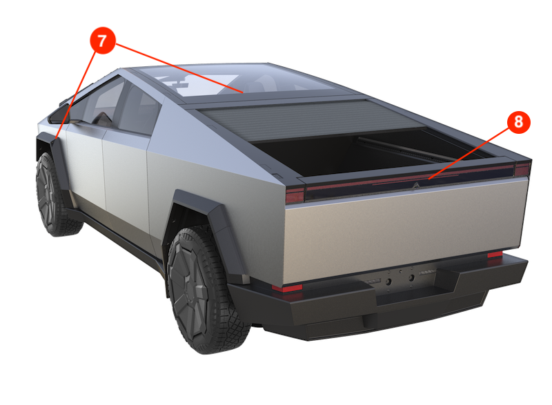 |
| 1. Front fascia camera 2. Driver Assistance Electronic Control Unit (ECU) 3. Global Navigation Satellite System (GNSS) Antenna 4. Forward-facing camera assembly with 2 cameras 5. Cabin camera 6. B-Pillar cameras (x2) 7. Side fender cameras (x2) 8. Rear-view camera |
| Component Location Overview - Cybertruck |
The above listed Driver Assist hardware interfaces with software running on the Driver Assistance electronic control unit (ECU), providing the driver with features like Traffic-Aware Cruise Control (TACC), Autosteer, Autopark, Forward Collision Warning, and Automatic Emergency Braking. Cameras and sensors give the vehicle a 360-degree view, which allows the vehicle to:
- Identify the road layout by detecting lane markings, curbs, barriers, and other obstacles.
- Identify a suitable travel path and speed.
Component Specificationslink
Driver Assistance ECUlink
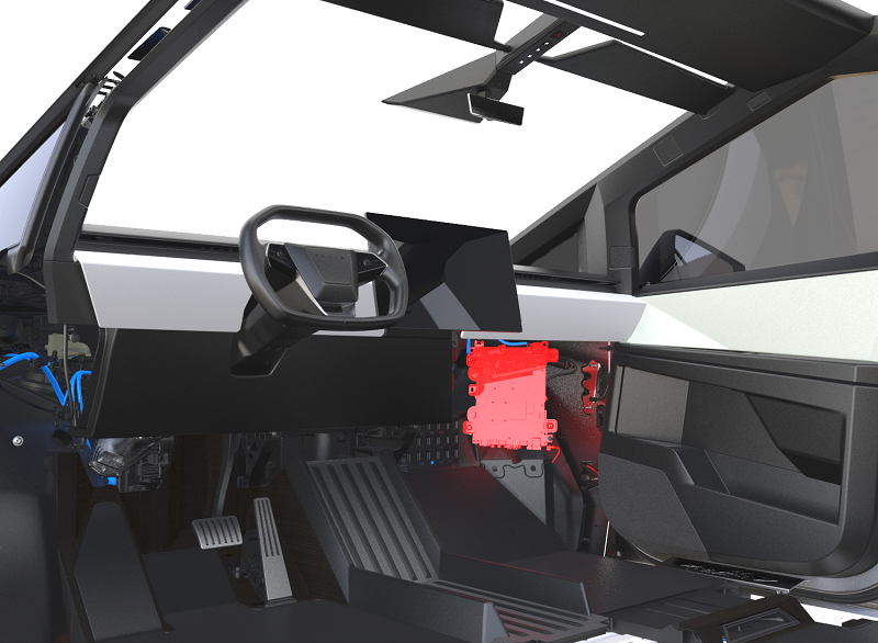
The Driver Assistance ECU (also known as DAS ECU or Autopilot ECU) is part of the car computer and is mounted in a portrait orientation to the right front casting reinforcement in the cabin behind the Glove Box. Refer to the Infotainment Theory of Operation for additional information about the car computer.
The main functional components of the Driver Assistance ECU:
-
Autopilot Primary Processor (APP)
-
Autopilot Backup Processor (APB)
-
Autopilot Secondary Processor (APS), one each in APP and APB
- GNSS receiver
-
Inertial measurement unit (IMU)
-
Two 8 port Ethernet switches for Etherloop support
- Camera inputs
| Common Abbreviation | Definition |
|---|---|
| ESP | Electronic Stability Program Electronic Control Unit (ECU) |
| PEPS | Primary Electric Power Steering |
| PSFA | Primary Steering Feedback Actuator |
| RCM | Restraints Control Module |
| DI | Drive Interface (Integrated into Left Vehicle Controller (VCLEFT)) |
| ICE | Infotainment and Connectivity Electronic Control Unit (ECU) |
| TASC | Tesla Adaptive Suspension Controller |
| VCBATT | Battery Vehicle Controller |
| VCLEFT | Left Vehicle Controller |
| VCRIGHT | Right Vehicle Controller |
| VCFRONT | Front Vehicle Controller |
 |
|---|
| Car Computer Location |
Specificationslink
- Autopilot ECU has two separate electrical circuits known as Rail A and Rail B that provides a path to connect and power the on-board components.
- These rails are connected to pins on separate connector assemblies on the Autopilot ECU.
- VBAT-A from VCRight controller powers Rail A and the components connected to it.
- VBAT-B from VCLeft controller powers Rail B and the components connected to it.
- Input Voltage range: 38V to 50V, Nominal: 48V
Connection and Interfaceslink
 |
|---|
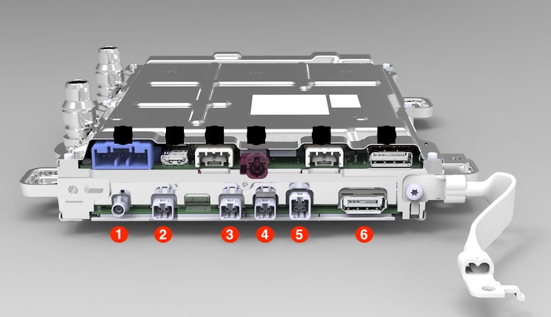
| 1. GNSS Antenna 2. Front fascia camera + Spare (dual connector) 3. Side fender cameras (dual connector) 4. Cabin camera and forward-facing fisheye camera (dual connector) 5. Rear-view camera, forward-facing main camera, and B-pillar cameras (quad connector) 6. B-side power |
| Driver Assistance ECU Connectors (Bottom Side) |
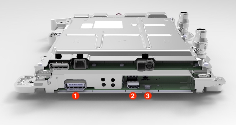 |
|---|
| 1. A-side power and Etherloop connection to VCRight 2. Not connected / Diagnostic port 3. Not connected / Diagnostic port |
| Driver Assistance ECU Connectors (Top Side) |
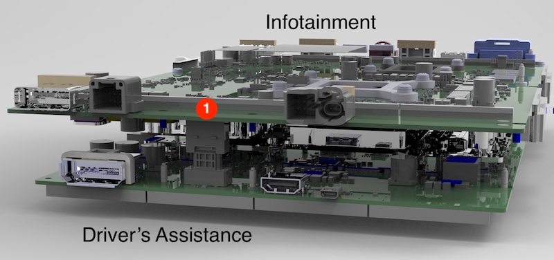 |
|---|
| 1. Etherloop connection and Ethernet bridge to Infotainment board |
| Driver Assistance ECU Connectors (Internal Board to Board) |
Etherlooplink
In Cybertruck, there are numerous distributed computers that cooperate to control the vehicle's behavior. These controllers communicate locally with each other through many small communication networks.
In order for messages to be shared throughout the vehicle, the small networks are connected to one large, high-speed Ethernet network, called Etherloop. This new central Ethernet design replaces the numerous main CAN networks (Body, Vehicle, Party, Chassis, Powertrain, etc.,) that were used on previous platforms.
Etherloop connects the Infotainment, Autopilot, High Voltage battery, and left, right and rear vehicle controllers. Developed to simplify and strengthen the vehicle communication network by reducing the amount of cross-car CAN wires, Etherloop also adds message redundancy and increased logging capability. Each node connected to Etherloop has a switch to manage Ethernet traffic flow.
Etherloop runs through the two eight port Ethernet switches on board the Driver's assistance ECU, each switch being a separate node in the loop. Each switch is also connected to its corresponding SOC (APP or APB) and responsible for data transfer from these autopilot processors on to the Etherloop and vice versa.
The Infotainment and Driver assistance ECUs are connected by a board to board connector inside the Car Computer. The Etherloop connections between them travel through this connector.
For detailed information on Etherloop and vehicle communication, refer to Electronic Control Modules and Vehicle Communication section of the Theory Operations, under Electrical.
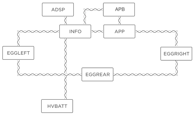 |
|---|
| Driver Assistance ECU and Etherloop Connections |
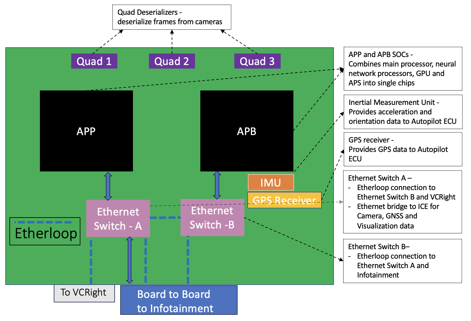 |
|---|
| Functional Units Inside Driver Assistance ECU and Essential Outside Connections |
Driver Assistance ECU Groundinglink
The Driver Assistance ECU's enclosure is grounded to the vehicle chassis ground through one ground strap and bolts from the enclosure to vehicle body in white. This is the primary ground path for the power received from VC Left and VC Right controllers.
When the Driver Assistance ECU is serviced, this ground strap and enclosure bolts should be properly secured before the vehicle or Driver Assistance ECU is powered up. The lack of primary ground path through the ground straps and bolts will force the input current to take the high impedance return via the camera coax cables(if connected) and potentially damage the cable.
Main Processors (APP & APB)link
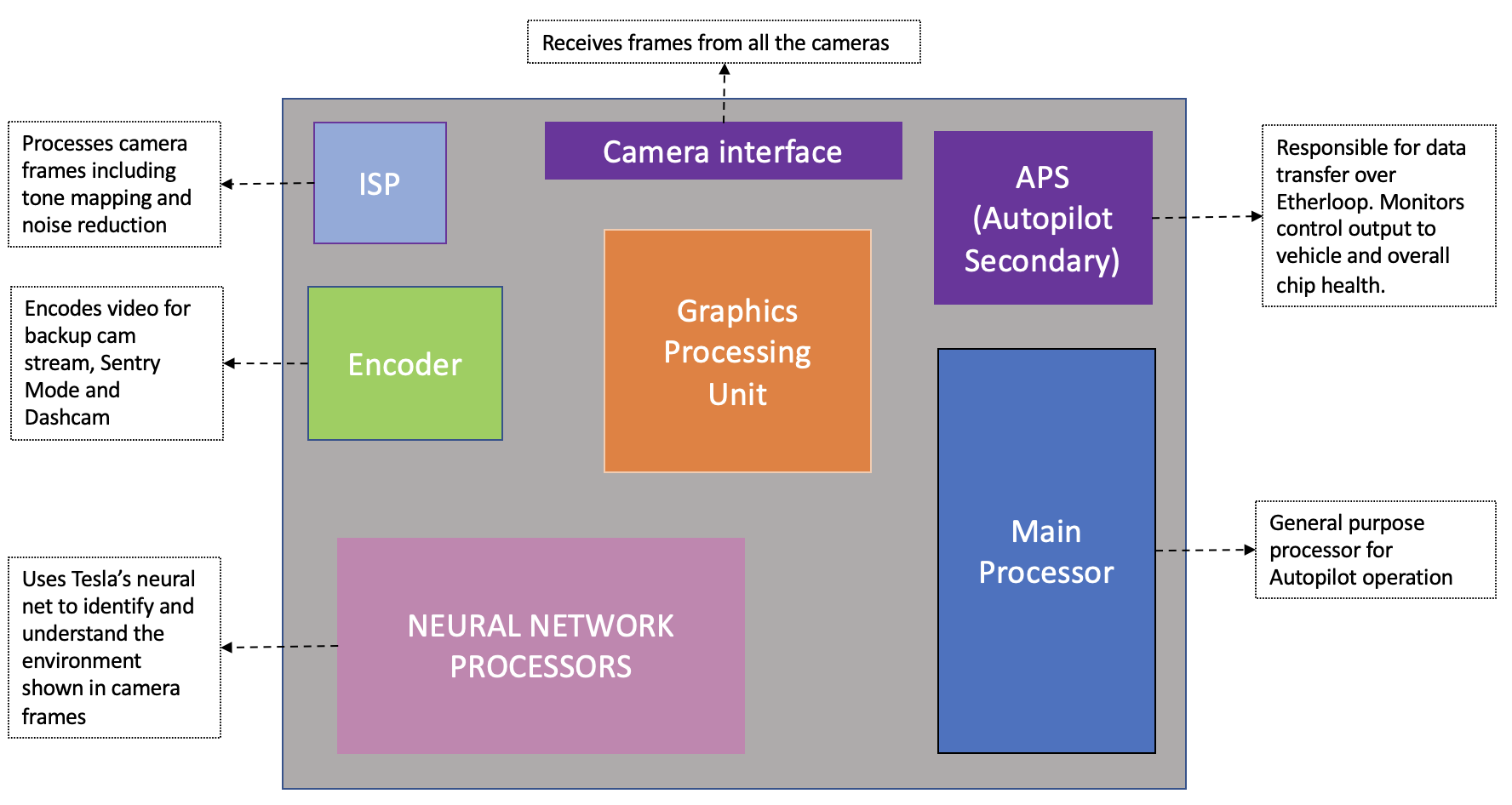
The Autopilot circuit board is equipped with 2 system-on-chip (SoC) units referred to as APP (or Autopilot-A) and APB (or Autopilot-B). These SoC units integrate several different processors on a single chip, such as the main processor, the secondary processor - APS (Autopilot Secondary), graphics processing unit (GPU), neural network processors, and camera interface. These components interface with other sensors and processors on the Driver Assistance ECU to provide Autopilot features and camera streaming capability.
The Autoplot secondary processor (APS) on these SoCs acts as a translator and converts the Ethernet frames received over Etherloop into CAN frames and vice versa.
Functions integrated into the SoC processor:
| Functional Unit | Unit Description |
|---|---|
| Camera Interface | Receives camera data sent from the 3 deserializers. |
| Image Signal Processor (ISP) | Processes camera frames to improve readability. |
| Camera Stream Encoder | Encodes video streams to be sent elsewhere in the vehicle, including the backup camera stream, Sentry Mode, and Dashcam video recording. |
| Neural Network Processors | Runs Tesla’s neural networks to understand the data contained in each camera frame (identifying lane lines, other vehicles, road hazards etc.). |
| General Purpose / Main Processor | Runs Tesla’s Autopilot software to perform all tasks necessary for Autopilot features, such as controlling cameras and other DAS components, transmitting DAS control data to other components of the vehicle etc. |
| Graphics Processing Unit (GPU) | Provides graphical processing and acceleration for camera frames. |
| Autopilot Secondary (APS) | Ensures all DAS related subsystems (including the DAS board / SoCs) are healthy and all commands to take control of the vehicle are valid. |
 |
|---|
| AP4 SoC Overview |
Ethernet Switchlink
Driver's assistance ECU has two onboard 8 port Ethernet switches, each one configured and controlled by its appropriate primary processor - APP or APB.
The Ethernet switch controlled by APP interfaces with the etherloop on three of its eight ports. It also provides a dedicated Ethernet link to Infotainment ECU via another port over the board to board connector. The Autopilot visualization data, camera data streams and GNSS data is transferred over this link with maximum speeds of up to 2.5 Gbps.
A private serial Gigabit Ethernet link between APP and APB helps them monitor and exchange private data between the processors.
Fusinglink
Fusing is a process to get Driver Assistance ECUs from an insecure state (unfused) to a secure state (fused), where only intended production firmware from Tesla is allowed to run on them. Fusing is done by blowing miniature fuses inside of the processors before those ECUs are installed in vehicles or available as parts. Only fused Driver Assistance ECUs are allowed in production vehicles.
Tip
Details on the Driver Assistance ECU fusing state can be found in Garage under Vitals > DAS > Security DAS.
Thermal Managementlink
The car computer is a part of the battery coolant loop between the chiller and the HV Battery. The location makes sure there is sufficient cooling for the thermally sensitive components on the Autopilot board.
The car computer assembly has a cold plate between the Infotainment and Autopilot board. Sections of the cold plate are raised and in thermal contact with the processors, memory chips, and other electronic components. Coolant entering the car computer exchanges heat with the cold plates, which are in thermal contact with the components allowing to effectively dissipate the heat generated by the processors and regulate temperature.
The Autopilot main processor's operational temperature range is -40°C (-40°F) to 105°C (221°F). As the temperature of the Autopilot processors increases, a higher coolant flow rate is requested. If the Autopilot processor's temperature exceeds the operational temperature range, the processor and autopilot software tasks will shut down, and Autopilot features will not be available.
Camera Image and Data Transportlink
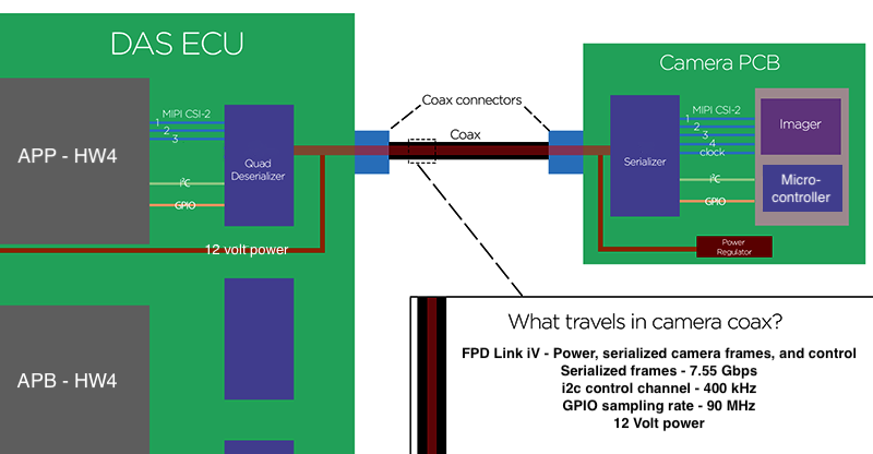
The Driver Assistance ECU connects to all cameras via separate coaxial cables and over those it provides direct current (DC) power to the camera, control signals and streams data from the image sensor.
The interface used to transport video from the cameras to Autopilot ECU is known as a Flat Panel Display link (FPD). FPD-Link transfer works by combining input data into packets or frames in order to be transferred serially at higher speed. Cybertruck uses FPD-Link IV which supports frame transfer rates of up to 7.55 Gbps.
The serializer of the camera will create a serial data stream of the captured image and control data. Meanwhile, the ECU deserializer will recreate the image from the data stream and can receive or send camera control data. The DC power for the camera is coupled onto the coaxial cable at the Driver Assistance ECU and decoupled at the camera without affecting the transmission of serial data.
One deserializer can access up to 4 cameras. Therefore, a failure of one deserializer may result in the loss of all connected camera data streams.
 |
|---|
| Camera Data Stream |
All HW4 cameras contain a micro-controller, which initializes the image sensor on the camera. For the Driver Assistance ECU to capture image data from the camera, it needs to initialize the involved hardware components in the following order:
- Initialize the deserializer of the Driver Assistance ECU.
- Initialize the serializer of the camera.
- Verify if the image sensor on the camera has been initialized by the onboard microcontroller.
If a component fails to initialize during the above sequence, then an appropriate alert will be set dependent on which camera is at fault. These alerts can be caused by an internal hardware fault of the camera or the Driver Assistance ECU but also by a poor connection between both components.
Once the involved hardware components are initialized, the camera starts to stream image data. Missing or corrupt image data will cause a stream exit alert for that specific camera. Damaged coaxial cables or cables with an incorrect characteristic impedance may cause a stream exit alert, as the ability to transmit data reliably at high speed is compromised.
Deserializer Configurationlink
Deserializer 1
- Port 0: Main camera
- Port 1: Left B-pillar camera
- Port 2: Right B-pillar camera
- Port 3: Rear view camera
Deserializer 2
- Port 0: Right repeater camera
- Port 1: Left repeater camera
- Port 2: Cabin camera
- Port 3: Fisheye camera
Deserializer 3
- Port 0: Front fascia camera
- Port 1: Unused
- Port 2: Unused
- Port 3: Unused
Camera Calibrationlink
Intrinsic Calibrationlink
The Driver Assistance ECU stores information about the focal length, optical center, and lens distortion for each camera, called intrinsic calibration. Those values are considered in camera frame processing to ensure each frame is an accurate and repeatable depiction of the real world.
Extrinsic Calibrationlink
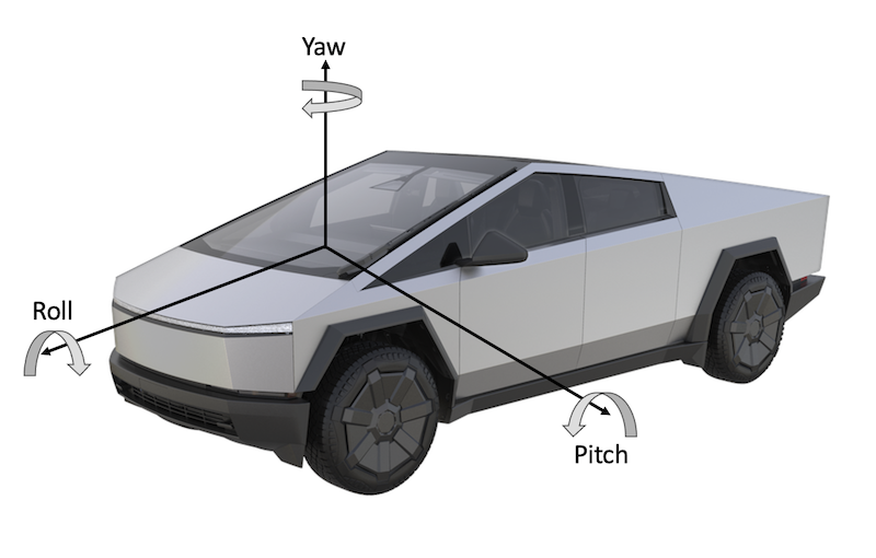
All vehicle cameras need to be calibrated to learn their position and orientation relative to the vehicle's centerline. While driving on roads with clearly marked lines, the Driver Assist ECU can deduce mathematically exactly where each camera is pointed and learn the values of horizontal (yaw) and vertical (pitch) misalignment. This is possible as camera positions are linked to the vehicle configuration and the vehicle's trajectory is known using inertial measurement unit (IMU) data (velocity, yaw, and acceleration).
 |
|---|
| Camera Pitch, Roll, and Yaw |
The camera calibration progress (in percentage %) is a confidence metric in this calibration. It does not necessarily mean at 95%, for instance, that 95% of the necessary driving has been completed but rather a 95% degree of confidence in the current calibration values. Once the camera calibration progress reaches 100%, the camera is considered calibrated and Autosteer will become available instantly. The vehicle will not "de-calibrate", even if calibration progress decreases later on, unless calibration is manually cleared. The forward-facing cameras and all other cameras will continuously calibrate while driving. The quickest way to calibrate a camera is by driving on the middle lanes of the middle lanes of straight, well-marked highways in good weather conditions.
Tip
- Clearing camera calibration without any mechanical camera adjustment will not change how the vehicle behaves once the cameras are re-calibrated. The Driver Assist ECU will only relearn the previous calibration values.
- Camera calibration should be cleared whenever a camera is removed, adjusted, or replaced. The driver may experience erratic Driver Assist feature behavior until the Driver Assist ECU fully learns the new calibration values if the previous calibration values are not cleared.
- Camera calibration is constantly updated as the vehicle is driven.
Firmware Updatelink
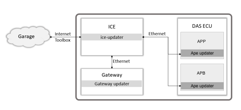
Autopilot ECU has its own updater process and receives a dedicated firmware package over Ethernet. When a firmware job is created, the DAS ECU firmware package (a SquashFS, compressed file system type) is downloaded to the Infotainment ECU / CID and transferred by the ice/cid -updater to the APE-updater.
Each APS is updated together with the corresponding APE processor package received via Ethernet.
 |
|---|
| Simplified DAS Firmware Update |
If a firmware job fails when updating the Driver Assistance ECU, confirm the following:
- DAS ECU primary processor(s) and their updater process is running.
- Ethernet connection to the DAS ECU is stable.
- No connectivity issues prevent firmware packages from downloading.
Diagnostics, Serviceability, and Calibrationlink
Alerts are set by the Driver Assistance ECU for the following reasons:
- ECU internal issue detected
- Issue communicating with the cameras
- Poor or no camera visibility
- Cameras are uncalibrated, their calibration is updated or out of specification
- Controller Area Network (CAN) messages or Ethernet frames from other ECUs are not received or have invalid data
-
Issue with the camera heater grid
-
Issue with the internal GNSS receiver or GNSS antenna
- Issue with the internal Ethernet switch(es)
- Main processor(s) not running as expected
-
ECU temperature is too low or too high
-
Request for additional cooling
Other alerts are set when Driver Assistance features are activated, canceled or unavailable but do not relate to the Driver Assistance ECU itself.
Inspect the following before replacing the Driver Assistance ECU:
- Ground and power wiring and connectors to the Driver Assistance ECU.
- Etherloop wiring and connectors to the Driver Assistance ECU.
- Coaxial wiring and connectors to the cameras.
The Driver Assistance ECU cannot be replaced as a separate part. The entire car computer must be replaced if there is an internal issue with the DAS ECU. After replacing the car computer, camera calibration process repeats.
Cameraslink
Driver Assistance system generation 4 vehicles are manufactured with cameras containing RGGB type camera sensors (color cameras).
 |
|---|
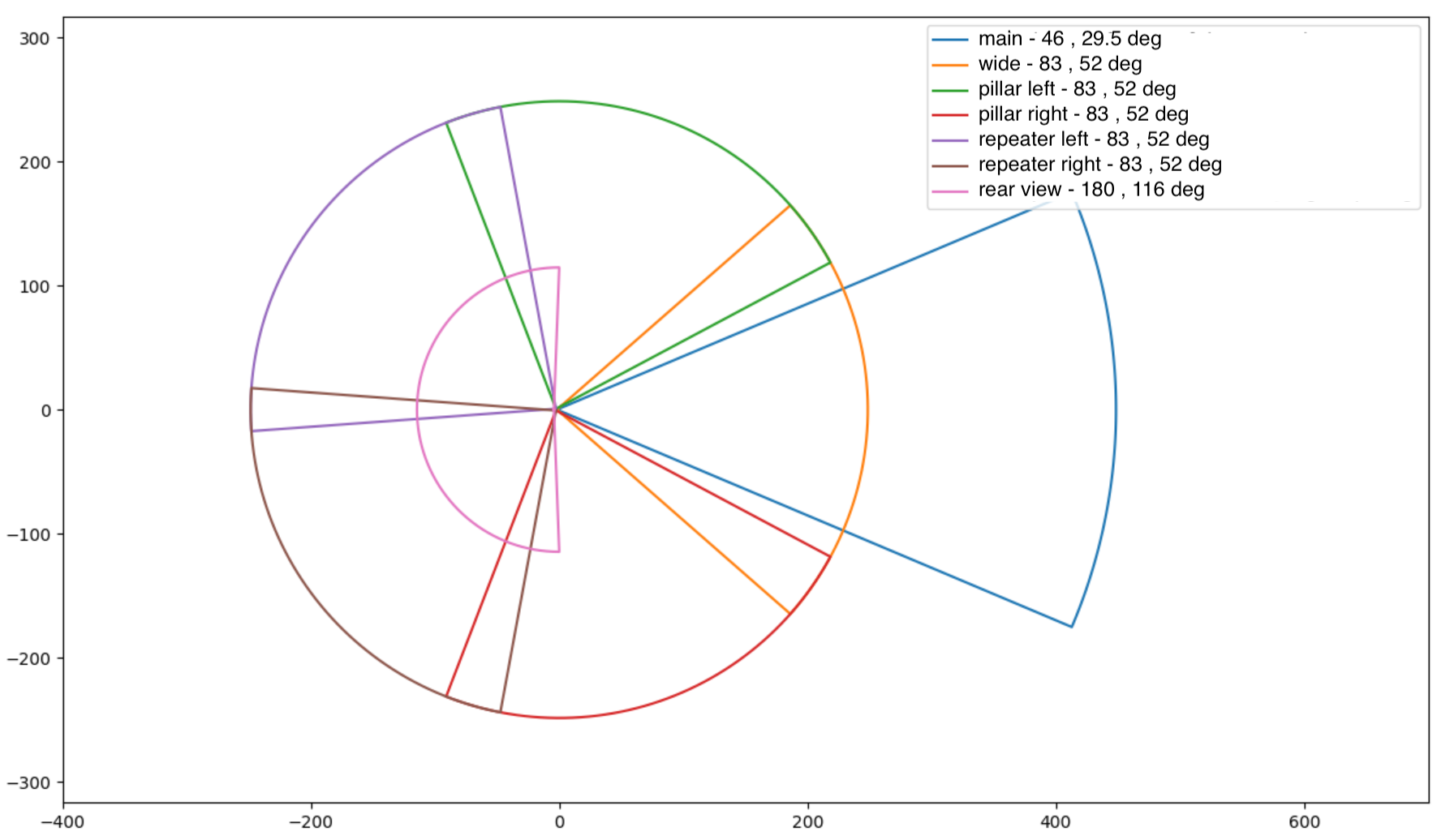
| HW4 Cameras - Field of View |
Each HW4 camera includes a microcontroller on the board that handles tasks like initializing the image sensor. The firmware running on the camera may need to be updated after a camera replacement. To update HW4 camera firmware, conduct a camera ping test utilizing Toolbox or perform a vehicle level software update/reinstall.
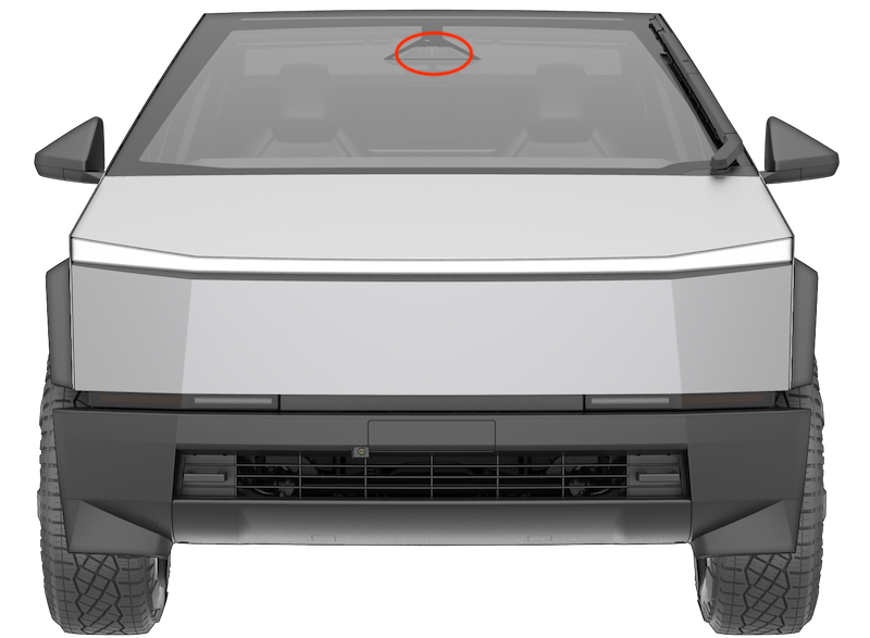
Forward Facing Camera Assemblylink
The forward facing camera assembly is mounted on the front windshield and consists of the main and fisheye cameras. Using two different focal lengths gives the system both a wide and deep field of view. This wide field of view allows for detecting objects and environments when planning an appropriate vehicle trajectory or vehicle action. These cameras must be precisely aligned and calibrated. Power to the cameras, control of the cameras, and image data from the cameras is provided through the coaxial wiring connected to the Driver Assistance ECU.
 |
|---|
| Forward Facing Camera Assembly Location |
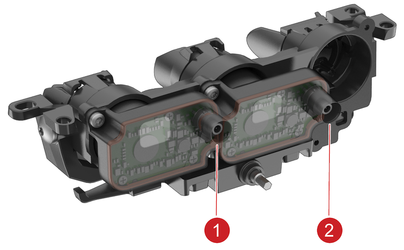 |
|---|
| 1. Main camera connector 2. Fisheye camera connector |
| Forward Facing Camera Assembly |
Main Cameralink
The main camera is one of the primary cameras used for providing a variety of Autopilot features and Auto High Beam. It can detect vehicles and objects up to 424m when conditions permit.
Specificationslink
- Field of view: 46 degree (horizontal) x 29.5 degree (vertical)
- Temperature range/rating: -40°C to +105°C (-40°F to +221°F)
- Operating voltage: 12V nominal (± 0.5V)
Fisheye Cameralink
The fisheye lens provides a wide field of view. It can detect vehicles and objects up to 205m when conditions permit and is used for providing a variety of Autopilot features along with Auto High Beam and Autowiper functionality.
Specificationslink
- Field of view: 83 degree (horizontal) x 52 degree (vertical)
- Temperature range/rating: -40°C to +105°C (-40°F to +221°F)
- Operating voltage: 12V nominal (± 0.5V)
Camera pitch verification service procedure is a method to approximate the camera pitch value without driving the vehicle to complete calibration. The pitch value approximation using the camera pitch verification procedure is not as accurate as the calibration derived from driving the vehicle but allows service to quickly verify that the camera pitch is roughly within the specifications and has the best chance to calibrate successfully when the vehicle is driven.
Therefore, whenever the forward facing camera assembly, or any component that contacts it, is physically adjusted or removed from the vehicle, camera pitch verification procedure is recommended to be performed. Refer to the Service Manual on how to perform this procedure. If the camera's pitch is approximated to be out of specification, it can be corrected with an adjustment screw next to the rear-view mirror. The vehicle then needs to be driven to complete calibration.
If the forward-facing camera is not operating as expected, inspect the connectors and coaxial cable from the camera to the Driver Assistance ECU.
An alert for each camera will be sent from the Driver Assistance ECU when:
- The ECU is unable to initialize cameras
- The camera image stream is interrupted
- An incorrect camera type is installed
- Main or narrow camera pitch is out of spec
Potential points of failure:
- Camera coaxial cable and connectors
- Camera assembly
- Driver Assistance ECU
The forward-facing camera(s) are replaceable as an assembly, it is not advised to replace the cameras individually as the cameras in the assembly are aligned to a specification at the manufacturer.
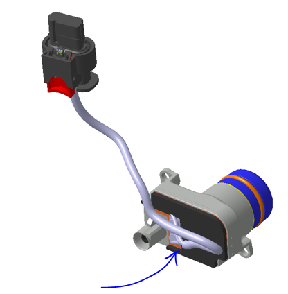
Windshield Camera Fan Assemblylink
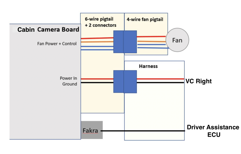
The windshield camera fan assembly is situated above the rear-view mirror and is directly mounted to the windshield bracket. The purpose of the fan is to improve air flow in the forward-facing camera's field of view region to help prevent and/or clear any condensation formed on the inside of the windshield. The windshield camera fan assembly receives power and control from the cabin camera module, which has a dedicated microprocessor for fan control. The power to run the fan is received by cabin camera module from the VCRIGHT controller. The cabin camera module has 1 coaxial connector and a six-wire pig tail with 2 connectors.
Fan control:
- Driver Assistance ECU receives and uses the data from the heating, ventilation, and air conditioning (HVAC) (Blower speed and Mode) system, cabin camera (temperature), and forward-facing camera (temperature and vision status) to calculate fan demand.
- Fan demand data is sent over the cabin camera coaxial cable to the microcontroller on the cabin camera module using i2C communication protocol.
- The microprocessor on the cabin camera module controls the fan power status and speed based on the fan demand it receives from Driver Assistance ECU.
 |
|---|
| Cabin Camera Module Topology |
Diagnostics, Serviceability, and Calibrationlink
If the windshield camera fan assembly is not operating as expected, inspect the connectors and wiring from the cabin camera module to the Driver Assistance ECU, the cabin camera module to the fan assembly, and the cabin camera module to the VCRIGHT. Inspect for any physical blockage preventing the fan operation like a trapped harness or dirt/debris.
Potential points of failure:
- Wiring and connectors
- Cabin camera module
- Fan assembly
- Driver Assistance ECU
- VCRIGHT
Cabin Camera with Infrared sensorlink
The cabin camera is situated above the rear-view mirror with an overview of the cabin. Power to the camera, control of the camera, and image data from the cabin camera are provided through the coaxial wiring connected to the Driver Assistance ECU.
The cabin camera module comes equipped with 2 infrared (IR) light emitting diodes (LEDs), which illuminate the cabin. The camera sensor is both natural light and infrared sensitive, allowing the camera to have visibility in all lighting conditions. The cabin camera module housing and the beauty cover (plastic trim piece over rear-view mirror) are both infrared transparent and the LEDs are internal to the module (not visible externally). The camera uses a dual band pass RGB-IR filter to maximize different lighting conditions during the day or night for higher quality images.
Cabin camera is being used for driver monitoring only on certain vehicle configurations and regions. If the system detects that the driver is inattentive, they are alerted with an audible chime and a visual warning is displayed on the screen reminding them to place hands on the steering wheel.
Specificationslink
- Field of view: 150 degree (horizontal)
-
IR LED wavelength: 940nm
-
Operating voltage: 12V nominal (± 0.5V)
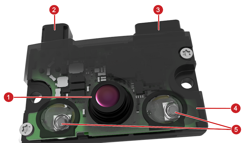 |
|---|
| 1. Camera lens 2. Camera coaxial connector 3. Pigtail with connectors for windshield camera fan and VCRIGHT
5. Infrared LEDs |
| Cabin Camera Module |
Side View Cameras (Rear Facing)link
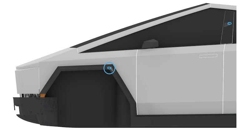
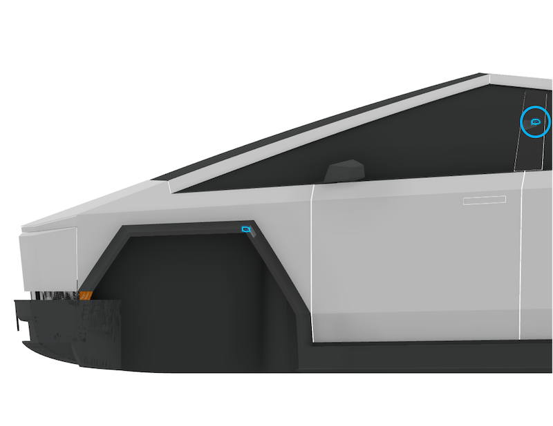
The side view cameras (rear facing) are mounted on the left and right front fender garnish over the wheel well. These cameras face in a rearward direction and are able to monitor rear blind spots on both sides of the vehicle. Power to the cameras, control of the cameras, and image data from the cameras are provided through the coaxial wiring connected to the Driver Assistance ECU.
 |
|---|
| Side View Camera (Rear Facing) Location |
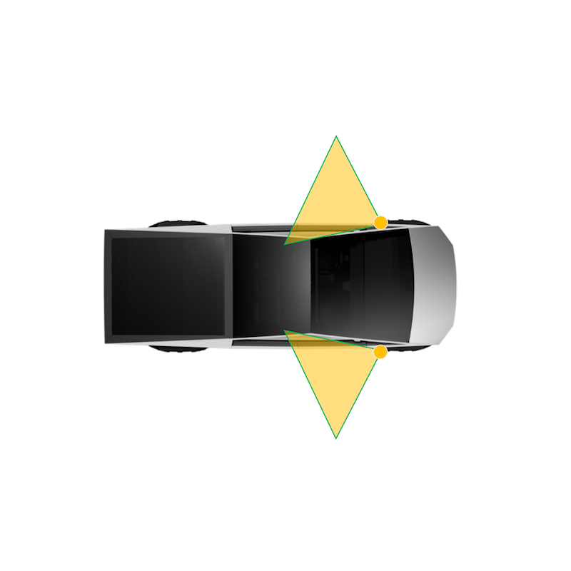 |
|---|
| Side View Camera (Rear Facing) Field of View |
Specificationslink
- Field of view: 83 degree (horizontal) x 52 degree (vertical)
- Temperature range / rating: -40°C to +105°C (-40°F to +221°F)
- Operating voltage: 12V nominal (± 0.5V)
Diagnostics, Serviceability, and Calibrationlink
If the side repeater camera is not operating as expected, inspect connectors and the coaxial cable from the camera to the Driver Assistance ECU.
The Driver Assistance ECU sets alerts for the items listed below when:
- The ECU is unable to initialize cameras.
- The camera image stream is interrupted.
- An incorrect camera type is installed.
Potential points of failure:
- Coaxial cable and connectors
- Camera
- Driver Assistance ECU
B-Pillar Cameralink
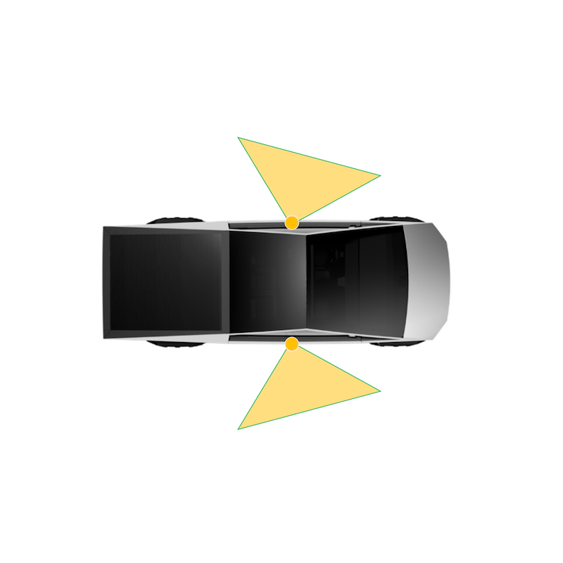
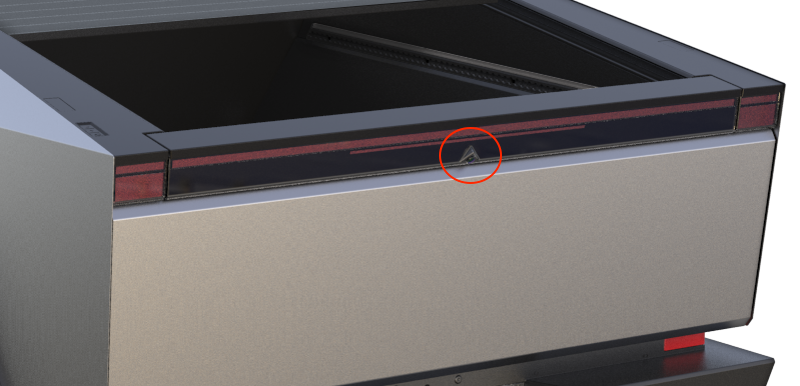
The B-Pillar cameras provide image data for each side and the front corners of the vehicle, which aid in detecting vehicles entering the vehicle's lane on a highway and cross traffic at intersections. The cameras are embedded into each B-Pillar behind the applique. Power to the camera, control of the camera, and image data from the cameras are provided through the coaxial wiring connected to the Driver Assistance ECU.
A portion of the B-Pillar applique glass around the camera field of view is equipped with a resistive type heater. The heater is either powered by VCLEFT or VCRIGHT depending on the side installed and will help in clearing ice and condensation built up in the camera field of view. This feature is not currently supported and will be activated through a future firmware update.
 |
|---|
| B-Pillar Camera Location |
 |
|---|
| B-Pillar Camera Field of View |
Specificationslink
- Field of view: 83 degree (horizontal) x 52 degree (vertical)
- Temperature range/rating: -40°C to +105°C (-40°F to +221°F)
- Operating voltage: 12V nominal (± 0.5V)
Diagnostics, Serviceability, and Calibrationlink
If the B-pillar camera is not operating as expected, inspect connectors and the coaxial cable from the camera to the Driver Assistance ECU. An alert for each camera will be set by the Driver Assistance ECU when:
- The ECU is unable to initialize cameras.
- The camera image stream is interrupted.
- An incorrect camera type is installed.
Potential points of failure:
- Camera coaxial cable and connectors
- B-pillar camera
- Driver Assistance ECU
The B-Pillar camera can be separated from the B-Pillar applique and is independently serviceable. After camera replacement, a calibration will occur during drive.
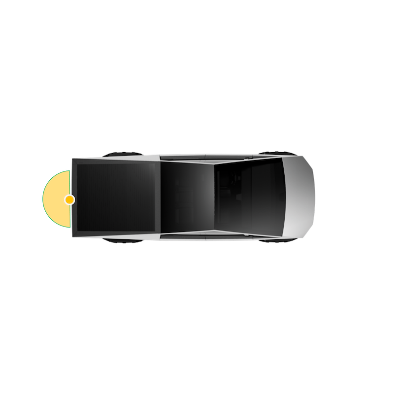
Rear-View Cameralink
The rear-view camera has a wide-angle lens, which enables the driver to view a large area behind the vehicle. The camera is connected to the Driver Assistance ECU and receives power from it. The image stream received is split for DAS ECU internal use and forwarded to the Infotainment ECU via Ethernet. This generation of DAS ECU does not utilize a coaxial jumper cable for the rear-view camera.
 |
|---|
| Rear-View Camera Location |
 |
|---|
| Rear-View Camera Field of View |
Specificationslink
- Field of view: 180 degree (horizontal) x 116 degree (vertical)
- Temperature range/rating: -40°C to +105°C (-40°F to +221°F)
- Operating voltage: 12V nominal (± 0.5V)
Diagnostics, Serviceability, and Calibrationlink
If the rear-view camera is not operating as expected, inspect the connectors and wiring from the camera to the Driver Assistance ECU, and from the Driver Assistance ECU to the Infotainment ECU. Confirm there are no issues with the touchscreen displaying the camera image.
Potential points of failure:
- Wiring and connectors
-
Camera
-
Infotainment and Connectivity ECU (ICE)
-
Driver Assistance ECU
The rear-view camera assembly is individually replaceable.
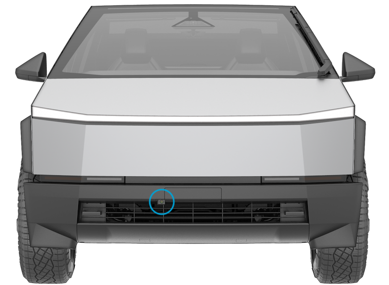
Front Fascia Cameralink
The front fascia camera provides a view of the area directly in front of the front bumper which may otherwise not be visible directly from driver's field of view. The camera is mounted into a hole cut out in the front fascia, next to the license plate holder and offset from center. A plastic trim cover piece with a hole cut out for camera lens protects the rest of the camera assembly from direct exposure to the environment and any road debris. Power to the camera, control of the camera, and image data from the cameras are provided through the coaxial wiring connected to the Driver Assistance ECU.
 |
|---|
| Front Fascia Camera Location |
A pressure washer nozzle installed onto the front fascia assembly directly above the front fascia camera lens provides a cleaning solution to wash away any dirt or ice accumalation on the camera lens. The nozzle is fed directly by a hose to the windshield wiper fluid reservoir. The power and ground to this washer pump is provided by VCLeft controller. The washer is activated by a switch on the UI.
A resistive heater grid directly in contact with the rear of the camera assembly provides a solution to melt any ice build up on the camera lens. The heater is powered by VCRight controller. This feature is not currently supported and will be activated through a future firmware update.
 |
|---|
| Front Fascia Camera Heater |
Specificationslink
- Camera Field of view: 180 degree (horizontal) x 116 degree (vertical)
- Camera Temperature range/rating: -40°C to +105°C (-40°F to +221°F)
- Camera Operating voltage: 12V nominal (± 0.5V)
- Camera heater Operating voltage: 12V nominal (± 0.5V)
Diagnostics, Serviceability, and Calibrationlink
If the fascia camera is not operating as expected, inspect connectors and the coaxial cable from the camera to the Driver Assistance ECU. An alert for each camera will be set by the Driver Assistance ECU when:
- The ECU is unable to initialize cameras.
- The camera image stream is interrupted.
- An incorrect camera type is installed.
Potential points of failure:
- Camera coaxial cable and connectors
- Fascia camera
- Driver Assistance ECU
If the camera heater is not operating as expected, inspect:
- Power/Ground to the heater
- Harness and connector terminals
- Heater adhesion to the camera back
If the pressure washer is not operating as expected, inspect:
- Power/Ground to the washer pump
- Harness and connector terminals
- Kinks and leaks in the hose
- Nozzle blockage due to dirt/debris
GNSS / GPS Antenna and Modulelink
The Global Navigation Satellite System (GNSS) antenna is located above the rear-view mirror under the forward camera's glare shield. The antenna board comes equipped with a metal reflector on the bottom side (towards the vehicle cabin) to provide electromagnetic interference (EMI) shielding from other nearby components.
 |
|---|
| GNSS Antenna Location |
The GNSS receiver is integrated into the Driver Assistance ECU. It uses a coaxial cable to power the antenna assembly and to receive Radio Frequency (RF) signals from the Low Noise Amplifier (LNA) built into the antenna assembly . The Autopilot secondary processor Autopilot Primary (APP) configures and controls the GNSS receiver. When the Driver Assistance ECU is not operational, GNSS is not available for all other consumers. To decrease the time until the location is calculated (GNSS fix), portions of the receiver module are always powered, even when the vehicle is asleep, to retain state.
The GNSS receiver is able to use Global Navigation Satellite System (GNSS) signals from the GPS, GLONASS, Galileo, or Beidou satellite constellations simultaneously (depending on the vehicle's region) and is capable of extracting carrier phase measurements from each available signal. The GNSS receiver transfers received satellite measurement observations to the Drive Assistance ECU processor, which uses a software Positioning Engine to estimate the location of the vehicle using the carrier phase measurements generated by the receiver. The Positioning Engine is enabled to receive two frequency bands from each satellite constellation - L1 and L5. Additionally, the Positioning Engine receives data from the Inertial Measurement Unit (IMU) and the vehicle’s wheel speed sensors to augment the GNSS measurements. The IMU uses gyroscopes and accelerators to estimate the motion and orientation change of the vehicle while wheel speed sensors detect incremental motion of the vehicle's tires. Through a process known as sensor fusion, the Positioning Engine combines data from the GNSS system, the IMU, and the wheel speed sensors to track the position of the vehicle. The process produces a solution that is more accurate than can be generated from GNSS measurements alone and can continue to track the vehicle even when GNSS signals are not available for short periods of time. This improves the accuracy and sensitivity of the position estimates used by features like Autosteer and Smart Summon.
If there is limited satellite reception (like in tunnels or underground parking), the Positioning Engine will attempt to estimate the position with just the wheel speed and IMU data. This is called "dead-reckoning", and while accurate over short distances, the estimate will diverge with distance traveled by the vehicle until a satellite signal is regained. Generally, the Positioning Engine needs a minimum of four satellites in view from a single constellation to generate a GNSS fix and regain a fully fused solution that will not drift with time.
Note
While GPS is technically just one of the satellite constellations, GPS is widely used as a synonym for the GNSS in general.
Specificationslink
-
GNSS antenna supply voltage: 5V nominal (3-5V range)
-
Operating temperature GNSS receiver: -40°C - 105°C (-40°F - 221°F)
- Operating temperature GNSS antenna: -40°C - 105°C (-40°F - 221°F)
Diagnostics, Serviceability, and Calibrationlink
If GNSS is not operating as expected, make sure that the Driver Assistance ECU is operational. Inspect the coaxial connectors and wiring from the Driver Assistance ECU to the GNSS antenna. The location information is shared with the User Interface (UI) over Ethernet, so while an issue with the connection does not affect the GNSS system, it will affect any features on the UI or other systems that depend on localization data. An alert will be set by the Driver Assistance ECU when:
- No or invalid data was received from the GNSS receiver.
- GNSS antenna is disconnected.
- GNSS receiver was reset.
- Voltage to the GNSS antenna is not as expected.
- Fusion mode status changes.
Potential points of failure:
- GNSS coaxial wiring and connectors
- GNSS antenna
- EMI from cameras and camera harnesses leak into the GNSS antenna and degrade the quality of the received signals
- Driver Assistance ECU
The GNSS antenna and the coaxial wiring can be replaced separately. The GNSS receiver is part of the Driver Assistance ECU and can only be replaced as a whole. After replacing either part, GNSS calibration is not required.
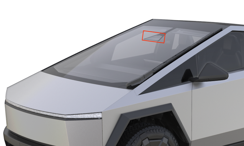
Camera Heater Gridlink
 |
|---|
| Camera Heater Grid Location |
The camera heater grid is controlled by the Driver Assistance ECU but electrically driven by the right vehicle controller (VCRIGHT) and is used to clear the front-facing camera view of condensation, snow, or ice.
The heater grid will be activated when defrost is requested or when Autopilot anticipates ice or condensation based on occlusions and environmental conditions. The heater grid will never operate above +30°C or +86°F ambient temperature.
- Windshield temperature is above the activation temperature (+6°C or +44.6°F).
- Windshield defrost and preconditioning are off.
Diagnostics, Serviceability, and Calibrationlink
If the heater grid is not working as expected, make sure to inspect the wiring to it. Confirm the above enable conditions are met and that the ambient and windshield temperature sensors (if present) are reporting correct values.
An alert will be set by the Driver Assistance ECU when a short or open circuit is detected in the camera heater grid. Potential points of failure:
- Wiring and connectors
- Ambient temperature sensor
- Temperature sensor near windshield
- Driver Assistance ECU
The camera heater grid is part of the windshield and can only be replaced as a whole. After replacing the windshield, camera pitch angle verification is required. The camera heater grid is part of the windshield and can only be replaced as a whole. After replacing the windshield, camera pitch angle verification is required.
Driver Assist Featureslink
Note
Not all Driver Assist features are available in every country. See the local Owner's Manual on Feature Availability and if there are different conditions for activation.
Traffic Aware Cruise Control (TACC)link
| Sensors and Data Used | Forward facing cameras:
|
| Speed limitations | Minimum speed for activation:
|
TACC maintains a driving set speed in the same way as standard cruise control but can also adjust the speed of the vehicle based on the distance to other vehicles in the same or adjacent lane (Undertake Assist). TACC will adjust the speed based on map data and during manual lane changes, reduce speed to target lane vehicles. TACC can be activated once traveling faster than 5 mph or 8 km/h, unless certain conditions allow an activation at even lower speeds. At standstill, TACC will activate if a vehicle is at least 5 feet (150 cm) detected ahead.
TACC is enabled by pressing the right scroll wheel on the steering wheel once, if configured in UI settings. TACC will set the detected speed limit (see Speed Assist) or the current driving speed as cruise speed, whichever is greater. When a speed limit is detected and shown in the cruise control symbol, this speed (+ possible speed warning offset) will be set as cruise speed.
If TACC is active, speed can be increased or decreased by moving the right scroll wheel up or down, or by using the ± icons on the UI, in 1 km/h (1 mph) or 5 km/h (5 mph) increments. To adjust cruise speed to a new speed limit determined by Speed Assist the driver can cancel and re-engage TACC or touch the speed limit sign on the UI. Cruise can be canceled by the driver by pressing the brake or the right scroll wheel.
Cruise will not be available when:
- The speed drops below 5 mph / 8 km/h and no lead vehicle detected.
- Driving speed exceeds 90 mph or 150 km/h.
- The driver's seat belt is unbuckled.
- The door is opened.
- The trunk or frunk is opened.
The driver can choose 7 different following distances via the UI touch buttons.
The distance will increase when the wiper activity suggests poor road conditions or ambient temperature is low (< 3°C / 38°F).
Diagnostic Informationlink
If Traffic Aware Cruise Control does not become available, check:
- If a right scroll wheel press is logged.
If Traffic-Aware cruise control does not work as expected or aborts, check:
- If vehicle has been driven under mentioned limitations.
- For cruise control related alerts.
Curve Speed Adaptationlink
Curve Speed Adaptation (CSA) is a feature of TACC. CSA reduces the vehicle's speed in anticipation of upcoming curves or bends in the road. This is done by temporarily slowing the vehicle down to an appropriate speed.
CSA activates when:
- Taking a highway exit.
- Predicted lateral acceleration along the most probable path reaches a certain threshold (uses either local navigation data or online Tesla maps).
- Current measured lateral acceleration of the vehicle reaches a certain threshold.
Fleet Speedslink
Fleet Speeds helps to slow the vehicle down to an appropriate speed when entering and exiting highways or driving on interchanges with Autosteer or TACC active. Speed will be reduced to the average speed that other Tesla vehicles drove on that road section but will not exceed the speed limit set by the driver. The set speed on the UI will be reduced in increments of 5 mph or 10 km/h rounded up to match the average Fleet Speed, though speed will not drop below 25 mph or 40 km/h. As long as Fleet Speeds is active, an animation of the circle around the set speed value will be shown on the UI. Drivers can override the new speed with the accelerator or brake pedal (as for TACC in general) if they consider it inappropriate.
Entering highways (on-ramp):
- Fleet Speeds might slow the vehicle down (depending on current set speed).
- Speed can change dynamically similar to how the fleet reported speed changes.
- Once the vehicle is on the highway, it will accelerate back to the previous set speed.
Highway interchanges:
- Fleet Speeds might slow the vehicle down (depending on current set speed).
- Speed can change dynamically similar to how the fleet reported speed changes.
- Once the vehicle is in targeted space, it will accelerate back to the previous set speed.
Exiting highways (off-ramp):
- Fleet Speeds might slow the vehicle down (depending on current set speed).
-
Speed can change dynamically similar to how the fleet reported speed changes.
-
Upon leaving the exit, Fleet Speeds will be actively controlling the speed for at least 100 m (110 yd) up to 2 km (1.2 mi) until the next road speed limit is detected.
- Fleet Speeds becomes inactive after either the new detected speed limit is set, or the previous set speed is restored.
Diagnostic Informationlink
Fleet Speeds cannot be deactivated but depends on the availability on map data of the fleet's average speed. If Fleet Speeds does not work as expected or at all, check for incorrect localization to nearby roads resulting in incorrect speed adjustments.
Overtake Accelerationlink
When Traffic Aware Cruise Control is active, Overtake Acceleration helps passing a vehicle more quickly by briefly reducing the following distance to the target in front with the turn signal active. Overtake Acceleration will engage when:
- TACC is operating and detects a vehicle in front.
- No obstacles or vehicles are detected in the target lane.
-
Speed is above 72 km/h (45 mph) but below the TACC set speed.
-
Accelerator pedal is not pressed.
Overtake Acceleration cancels when:
- Cruise set speed is reached.
- Changing lanes takes too long.
- Vehicle gets too close to the vehicle ahead.
Diagnostic Informationlink
There are no feature specific signals available in logs.
Passing Lane Assist (Undertake Assist)link
Undertake Assist or Passing Lane Assist is designed to prevent passing vehicles with TACC active in a lane where it is not legally allowed. For example, this applies to continental Europe, where in right-hand traffic vehicles have to be passed in the left lane, passing on the right is not allowed. If moving faster in the slower lane than a vehicle ahead in the faster lane, Undertake Assist will match the speed and prevent passing. This behavior can be overridden by pressing the accelerator pedal, disabling TACC, or changing lanes. It stays disabled until the next disable/enable cycle of TACC.
Diagnostic Informationlink
There are no feature specific signals available in logs.
If Passing Lane Assist does not work as expected or at all, confirm the following:
- Vehicle speed is above 50 mph or 80 km/h.
- TACC or Autosteer is active.
- The faster vehicle is not too close as the camera might not be able to capture it.
Autosteerlink
| Sensors Used | Cameras:
|
| Speed Limitations | Minimum speed for Autosteer activation:
|
Autosteer is used to assist the driver in steering the vehicle on main roads and highways. Autosteer is an extension of TACC and keeps the vehicle in its lane while controlling cruise speed based on target vehicles ahead or map data. Always refer to the Owner's manual for the latest Autosteer visualizations, as the user interface is subject to change.
A gray steering wheel icon appears on the vehicle UI to indicate that Autosteer is available for use, but not actively steering the vehicle.
The Autosteer feature uses the front camera(s) to recognize lane markings to center the vehicle. Based on camera inputs, the Driver Assistance ECU will calculate an appropriate driving path for the vehicle. The calculated steering output will be transmitted on the etherloop to be consumed by Primary Electric Power Steering and Primary Steering Feedback Actuator.
Autosteer is designed to correct for external disturbances that may affect the vehicle’s steering, such as crosswinds or poor wheel alignment. If obstacles like guard rails are detected on one side, Autosteer will offset the vehicle within the lane to increase free space there.
Different from TACC only driving, Autosteer restricts the maximum speed depending on the road's speed limit (only off highway). The driver can go above the speed limit by overriding with the accelerator pedal or setting a relative speed limit warning on the UI. If the speed limit of the current road is unknown a speed limit appropriate to the detected road class will be used.
While driving with Autosteer active, the driver’s hands are required to be on the steering wheel. This will be checked at certain intervals by querying the driver applied torque on the steering wheel by the power steering system. The interval varies by region, weather conditions, road geometry and class, detected vehicles, constructions zones, and speed. If the driver does not respond to the audio and visual reminders on the UI, Autosteer will abort and gradually slow the vehicle down to a standstill. If the driver chooses to ignore the "Apply light force to steering wheel" reminders 3 times or accelerates over the Autosteer speed limit, Autosteer will be disabled until the next drive cycle. If Autosteer is active but is unable to continue due to lack of information, the driver is required to take over steering control and is warned by a series of chimes and a driver-facing alert, "Take over immediately." While driving with Autosteer active, the driver’s hands are required to be on the steering wheel. This will be checked at certain intervals by querying the driver applied torque on the steering wheel by the power steering system. The interval varies by region, weather conditions, road geometry and class, detected vehicles, constructions zones, and speed. If the driver does not respond to the audio and visual reminders on the UI, Autosteer will abort and gradually slow the vehicle down to a standstill. If the driver chooses to ignore the "Apply light force to steering wheel" reminders 3 times or accelerates over the Autosteer speed limit, Autosteer will be disabled until the next drive cycle. If Autosteer is active but is unable to continue due to lack of information, the driver is required to take over steering control and is warned by a series of chimes and a driver-facing alert, "Take over immediately."
To cancel Autosteer the driver presses the right scroll wheel on the steering wheel once, moves the steering wheel, presses the brake pedal or shifts out of Drive. Normally, 2 to 4 Nm of torque on the steering wheel is required to cancel Autosteer, depends on the vehicle model and region of operation. When the turn signals are on, the amount of force to cancel Autosteer is ~1 Nm (depends on vehicle platform). When Autosteer is canceled, a chime will sound, UI displays the lane markings in white and the Autosteer icon changes from blue to gray.
Diagnostic Informationlink
If Autosteer will not activate, check:
-
If all Autosteer activation criteria is met (especially UI Autosteer setting is on, trailer mode is off, and lane markings are detected).
- If a right scroll wheel press is registered.
- If there are any alerts relating to the Driver Assistance ECU, cameras.
- If there are any Autosteer unavailable alerts.
If Autosteer does not perform as expected or aborts, check:
- If the vehicle is driven in conditions mentioned under limitations.
- If camera calibration is fully complete and the camera pitch is in specification.
- If there are any alerts on Autopilot steering angle or steering angle rate saturation indicating a potential issue in identifying lane markings.
- If there are any alerts on Autopilot aborting giving the reason why Autosteer could not continue steering the vehicle.
See also Traffic Aware Cruise Control, as some limitations can affect Autosteer behavior.
Auto Lane Changelink
Automatic Lane Change (ALC) is used to assist in changing lanes with Autosteer active. The minimum speed at which ALC is available depends on the region, adjacent lane speeds and road class.
- The driver's hands must be detected on the steering wheel before being able to activate Auto Lane Change.
-
Activation is only possible on major highways and well-marked local roads with multiple lanes.
-
Turn signal steering switch needs to be pressed to activate Auto Lane Change.
- Lane changes will abort if not completed within 5 seconds after using the turn indicator.
A successful Auto Lane Change is dependent on information from several sources:
- The forward-facing camera provides information about the location the current lane, adjacent lanes, lane line types, forks, road curvature, location of lead vehicle and objects that would prevent an Auto Lane Change.
- The side cameras provide location of objects and other vehicles that would prevent a lane change including vehicles in or approaching the blind spot.
If the current and target lane markings are found and hands-on is detected, Auto Lane Change will activate. At any point Auto Lane Change can abort under several conditions including:
- The lane lines are lost.
- The lane line type does not allow lane changes.
- A fork separates the lanes ahead.
- A toll both or construction is detected.
- Maps indicate the target and current lane will merge soon or the turn indicator is not responding.
If the cameras detect an object, the lane change will wait for it to pass. Once there are no objects that interfere with the Automatic Lane Change maneuver, the vehicle is brought closer to the vehicle in front of it with Overtake Acceleration and starts to depart the lane. If any of the above mentioned conditions are not met once the lane change commence, Auto Lane Change will abort the vehicle will return to the current lane.
The driver can also abort the lane change by pressing the brake pedal or moving the steering wheel (1 Nm torque required).
Automatic Lane Change performs one lane change at a time. Moving into a second lane requires activating the turn signal a second time after the first lane change is complete. Auto Lane Change is designed for use on main roads and highways only where lane markings are visible and clear, and the driving conditions are more predictable.
Diagnostic Informationlink
The only driver-facing indication of Auto Lane Change availability is the UI displaying outer lane markings of adjacent lanes.
If Auto Lane Change does not start, check:
- If all Automatic Lane Change activation criteria is met (especially the lane marking detection).
- If there are any alerts relating to the Driver Assistance ECU, camera(s), and/or ultrasonic sensors when equipped .
- If there are any Lane Change unavailable alerts.
If Auto Lane Change does not perform as expected or aborts, check:
- If the vehicle is driven in conditions mentioned under limitations.
- If the driver aborted the lane change (steering, pedal or turn indicator input).
- If there are any alerts relating to the Driver Assistance ECU, cameras .
- If there are any Lane Change abort alerts.
If Auto Lane change waits unexpectedly long, check:
- If there is a fast-approaching vehicle or a vehicle in the blind spot.
- If there are vehicles or objects nearby that vision could be unsure of location or speed.
Stop Light and Stop Sign Warninglink
Note
Stop Light and Stop Sign Warning is available in certain countries only.
When driving on Autosteer and the vehicle is expected to travel through a stop sign or red light, the driver will be alerted on the UI and via a chime to take over control. This feature will not slow down or stop the vehicle. Stop sign and traffic light locations are based on map data and if detected by the forward-facing cameras.
Diagnostic Informationlink
Whenever the Stop Light and Stop Sign Warning feature is activated, the traffic lights warning alert will be set in the log data.
Navigate on Autopilotlink
Navigate on Autopilot (NoA) is an Autopilot feature that uses Autosteer and Auto Lane Change to navigate the highway portion of a navigation route, including exits and interchanges. It will only be active on controlled access roads (highways, motorways, Autobahn etc.) with a navigation route and confirmed by the driver by selecting "Navigate on Autopilot" in the turn-by-turn direction list. If this feature is active, a blue line in front of the vehicle will be shown on the UI instead of the two blue lane lines for Autosteer. Refer to the Owner's Manual for the latest visualizations as the UI is subject to change.
Navigate on Autopilot combines lane information from the forward cameras and navigation information to estimate the current lane of the vehicle. A plan is created with the required lane changes and exits to follow the navigation instructions from the UI. This plan will include avoiding captive lanes and changing into exit lanes at a set distance before the off-ramp or fork. If Navigate on Autopilot suggests changing lanes or take an exit, an additional grey line is shown in the proposed direction.
Changing lanes requires confirmation by the driver, using either the right steering scroll wheel or the turn signal switches. If the driver does not confirm the maneuver, it will time out, and NoA will retry later if required to follow the navigation route. If the driver does not want to change lanes, the lane change can be rejected (or 'snoozed') from the UI. When available, no confirmation is needed when "Require Lane Change Confirmation" is off on the UI and lane changes will begin immediately. These automated lane changes are called uncommanded lane changes (ULC). They are functionally the same as an Auto Lane Change. If there is a vehicle blocking the lane change, it will show in red on the UI.
Lane changes will also be recommended based on the speed of other vehicles. If the current set speed is higher than the speed of the vehicle in front and the faster lane is empty or moving faster, NoA might recommend a lane change. An upcoming exit will prevent such a lane change away from the exit lane. The sensitivity of these lane changes can be configured to Disabled, Mild, Average and Mad Max. They are based on speed the difference between the lead vehicle and the current cruise set speed at which NoA will recommend changing to a faster lane (in Mad Max the speed difference is small). Where possible Navigate on Autopilot will move the vehicle out of the fast lane (most left lane in left-hand drive countries).
When driving in the US, the UI option "Use HOV Lanes" allows the use of high occupancy vehicle (HOV) lanes when set, so NoA will move in and out of these lanes but will avoid them if the UI option is not set.
After leaving controlled access roads or if GNSS localization, maps, or side cameras are unavailable, Navigate on Autopilot will fall back to Autosteer and notify the driver with a UI message and chime.
Diagnostic Informationlink
If Navigate on Autopilot does not activate when Autosteer is engaged, check:
- If the Navigate on Autopilot UI option is enabled.
- If Navigation is active with NoA and the current road allows NoA.
- If there are any alerts relating to the Driver Assistance ECU or cameras .
- If the current navigation maps are installed.
- If camera calibration is complete for front and side cameras.
If Navigate on Autopilot does not work as expected, confirm that the vehicle is driven in conditions mentioned under limitations.
Traffic Light and Stop Sign Controllink
Traffic Light and Stop Sign Control is designed to recognize and respond to traffic lights and stop signs, slowing vehicles to a stop when using Traffic-Aware cruise control or Autosteer. This feature uses the vehicle's forward-facing cameras, in addition to GNSS data, and slows the vehicle for all detected traffic lights, including green, blinking yellow, and off lights in addition to stop signs and some road markings. As vehicles approach an intersection, the touchscreen displays a notification indicating the intention to slow down. The driver must confirm that they want to continue, or the vehicle will stop at the red line displayed on the touchscreen's driving visualization.
Note
Traffic Light and Stop Sign Control is a BETA feature and works best on roads that are frequently driven by Tesla vehicles. Traffic Light and Stop Sign Control attempts to stop at all traffic lights, including green lights.
Diagnostic Informationlink
Limitations of Autosteer and Its Associated Functionslink
- Autosteer is unable to accurately determine lane markings. For example, lane markings are excessively worn, have visible previous markings, have been adjusted due to road construction, are changing quickly (lanes branching off, crossing over, or merging), objects or landscape features are casting strong shadows on the lane markings, or the road surface contains pavement seams or other high-contrast lines.
- Visibility is poor (heavy rain, snow, fog, etc.).
- A camera(s) or sensor(s) is obstructed, covered, or damaged.
- Driving on hills.
- Approaching a toll booth.
- Driving on a road that has sharp curves or is excessively rough.
-
Bright light (such as direct sunlight) is interfering with the view of the camera(s).
-
A vehicle is detected in the blind spot when the turn signal is engaged.
- Vehicle is being driven very close to a vehicle in front of it, which is blocking the view of the camera(s).
Autopark and Summonlink
Note
Autopark and Summon features are currently unavailable on this vehicle model, will be activated in the near future via firmware update.
| Feature | Specifications |
|---|---|
| Sensors Used | All cameras:
|
| Speed Limitations | Maximum speed for parking slot detection:
|
Autopark - Vision Basedlink
Autopark is designed to find a parallel or perpendicular parking location, control steering, brakes, and acceleration to park the vehicle. While driving below the maximum speed for Autopark, the onboard cameras are searching for a parking spot on the left and right side. The travel path of the vehicle during Autopark is determined by the Autopilot ECU.
Vision Based Autopark is available after the forward-facing cameras and the side repeater cameras have calibrated.
Autopark will abort when:
- A door is opened.
- Driver present is no longer detected.
- Torque is applied to the steering wheel.
- Driver shifts out of current gear.
- Driver presses the accelerator pedal.
- Driver pressing the brake pedal more than once.
Autopark will pause when:
- Driver applies the brake (after 30 seconds in pause the vehicle will shift into Park).
Specifications Parallel Parkinglink
A valid parallel parking space must be defined by a lead vehicle and a curb, which must be almost parallel to the vehicle. Parallel parking spaces cannot be detected only by painted boundary lines, requires a vehicle to be parked along the curb to present Autopark option.
- Minimum slot length: vehicle length + 1 m (3.3 ft)
- Minimum drive by distance: The vehicle's rear axle should be minimum 5 m from the rear axle's estimated final parking position at the end of Autopark maneuver.
- Maximum drive by distance: The vehicle's rear axle should be within 7.5 m from the rear axle's estimated final parking position at the end of Autopark maneuver.
Specifications Perpendicular Parkinglink
A valid perpendicular parking space must be defined by three boundaries, the boundaries can be painted lines or a physical curb. The detection of perpendicular parking spaces is purely based off of painted boundary lines or curbs and does not require a parked vehicle for reference, this allows for Perpendicular Autopark to be available at majority of parking spaces in most parking lots. If a curb or a painted boundary line is detected in the rear of the parking slot, it is respected such that the rear bumper does not cross the boundary line or line of the curb.
- Maximum slot width: vehicle width + 1 m
- Minimum drive by distance: Varies between different parking attempts, it depends on approach angle and turning radius required to get into the slot.
- Minimum lateral distance: 2.5 m from the entrance of the parking slot
- Maximum drive by distance: 4.5 m from the rear bumper
Diagnostic Informationlink
The UI will display a P icon when a possible parking spot has been detected (parallel or perpendicular), it is up to the user to decide if it is a valid detection. If from a driver's perspective a valid spot has been found but not shown on the UI, check for correct driving speed, parking slot dimensions or check if APP_w328_autoparkDegraded alert is set. The metadata of APP_w328_autoparkDegraded may indicate why a spot was not shown as available for Autopark or any other potential issues with the system. The presence of this alert does not indicate that Autopark feature is disabled, but the feature's performance may be degraded.
Parking spots are confirmed by the DAS ECU. It combines information from online and offline map data to determine if a spot detection is valid.
Autopark is not available in Valet mode, with open closures or on a steep gradient (>10% gradient). As this feature relies on cruise control functionality, it will also be unavailable when the Drive Inverter reports cruise is unavailable.
If Autopark does not start or aborts, check:
- If autopilot cameras have not calibrated, are not streaming, or are blocked.
- Logs for alerts that would indicate any of the systems used for Autopark faulted.
-
Logs for alerts indicating driver intervention.
-
Logs for alerts pertaining to the camera streaming.
- Logs for Autopark Control (APC) abort and activation alerts.
- Logs for alerts pertaining to Primary Electric Power Steering OR Primary Steering Feedback Actuator.
- Logs for alerts pertaining to Drive inverter.
If Autopark does not perform as expected, check:
- If the feature is used in conditions mentioned under limitations.
- Logs for alerts that would indicate any of the systems used for Autopark faulted.
- Logs for alerts indicating driver intervention.
Limitationslink
- The road is sloped. Autopark is designed to operate on flat roads only.
- Autopark is not available for angled spots, only parallel and perpendicular spots.
- Visibility is poor (due to heavy rain, snow, fog, etc.).
- The curb is constructed of material other than stone, or the curb cannot be detected.
- Painted boundary lines of parking spots are not clear or worn out.
- Indoor parking lots with glossy, reflective floors.
-
The target parking space is directly adjacent to a wall or pillar (for example, the last parking space of a row in an underground parking structure).
-
One or more of the cameras is damaged, dirty, or obstructed (such as by mud, ice, or snow).
- Weather conditions (heavy rain, snow, fog, or extremely hot or cold temperatures) are interfering with sensor operation.
Summonlink
Summon is a feature that can move the vehicle in and out of a parking space without a driver needing to be in it.
Once activated, Summon will travel as commanded forward or reverse for up to 12 m (40 ft) trying to avoid obstacles if possible, with a maximum speed of 1.6 km/h (1 mph). Summon will finish once the stop criteria (front or rear distance) from the touchscreen are met or the user requests a stop on the mobile app or key fob. Summon aborts when any of the following occur:
- A door handle is pressed.
- The front trunk or trunk button on the key fob is pressed.
- Driver intervenes by using with steering wheel, brake, accelerator pedal, or gear selection.
- If the vehicle cannot move for more than 2 seconds due to an obstacle.
Summon can be configured to open and close HomeLink garage doors once it has learned the GNSS location where it should send a HomeLink command. If an obstacle in the path of travel is detected in this location, Summon will assume it is a closed garage door and use HomeLink to open it (be aware that there is only one command to open and close via HomeLink). If the path is clear, Summon will continue and also close the garage door once finished. Summon is not looking at lane markings and will not attempt to line up with those.
Diagnostic Informationlink
If Summon fails to activate, check:
- If Summon is enabled on the UI.
- If all activation criteria are met (differs per region).
- If both phone with the mobile app and vehicle have connectivity.
- If key fob commands are registered.
- Logs for Summon (APC) abort and activation alerts.
If Summon does not perform as expected, check:
- If the feature is used in conditions mentioned under limitations.
- Logs for Summon (APC) abort and activation alerts.
Limitationslink
- The driving path is sloped. Summon is designed to operate on flat roads only (up to 10% grade).
-
A raised concrete edge is detected. Summon will not move the vehicle over an edge that is higher than approximately 1 in (2.5 cm).
-
Weather conditions (heavy rain, snow, fog, or extremely hot or cold temperatures) are interfering with object detection.
-
Vehicle is in Trailer Mode or an accessory is attached.
Smart Summonlink
Note
Smart summon feature is currently unavailable on this vehicle model, will be activated in the near future via firmware update.
Smart Summon adds several capabilities beyond the standard Summon feature. Rather than driving directly forwards or backwards, Smart Summon will drive to either the current GNSS location of the customer's phone commanding Smart Summon, or selected GNSS location via the phone app. Smart Summon utilizes data from all external surround vision cameras .
To use Smart Summon the user must position themselves in line of sight within approximately 65 meters or 213 feet (for EU vehicles up to 6 meters) of the vehicle.
Once Smart Summon is activated the vehicle will:
- Fold the mirrors in.
- Shift into Drive or Reverse.
- Turn the headlights on and commence driving, using turn signals where necessary, to get within 1 meter (3 feet) of the user or pin location.
Smart Summon will drive a total maximum distance of about 150 meters or 164 yards (for EU vehicles up to 20 meters). After that, the driver must enter the vehicle and enter gear to restart the distance counter. If Auto HomeLink is enabled in Summon options, HomeLink will automatically activate when starting Smart Summon with the vehicle in the garage. The mobile app will inform the user that HomeLink has been activated.
Smart Summon offers a Standby mode where the vehicle will continuously monitor its surroundings for a faster start-up of the feature. Even if Standby mode is activated, it will be disabled between 12:00 AM and 6:00 AM local time to conserve energy.
Diagnostic Informationlink
If Smart Summon fails to activate, check:
- If the feature is used in conditions mentioned under limitations.
- If GNSS localization of mobile phone and vehicle is correct.
- If mobile phone and vehicle have connectivity.
- If main, fisheye and repeater cameras are calibrated.
- If the user is within 65 meters or 213 feet (for EU vehicles up to 6 meters) of the vehicle with a clear line of sight.
- For alerts relating to the Driver Assistance ECU or cameras.
- EU vehicles only: If the phone is to the vehicle.
If Smart Summon does not perform as expected, check:
- If the feature is used in conditions mentioned under limitations.
- The environment Smart Summon was used in.
- For Enhanced Summon and Autopark abort alerts.
Limitationslink
- GNSS data is unavailable due to poor cellular coverage.
- The driving path is sloped. Smart Summon is designed to operate on flat roads only (up to 10% grade).
-
A raised concrete edge is detected. Depending on the height of the concrete edge, Smart Summon may not move the vehicle over it.
-
Weather conditions (heavy rain, snow, fog, or extremely hot or cold temperatures) are interfering with object detection.
-
Vehicle is in Trailer Mode or an accessory is attached.
Lane Assistlink
| Sensors Used | Cameras:
|
| Speed limitations | Blind Spot Warning
|
Blind Spot Warninglink
Blind Spot Warning, also known as Side Collision Warning, is designed as an advanced blind spot warning system that is able to detect vehicles at all 4 corners of the vehicle. Radiating lines around the vehicle avatar are shown on the UI when objects are detected by cameras . As a vehicle gets closer, the radiating line color changes from white, to yellow, and to red. When the driver activates the turn signal with a vehicle close in this direction, the UI will show the lane line next to it in red. If a collision is considered likely, a configurable chime will sound.
Diagnostic Informationlink
When Blind Spot Warning is not working at all, or not working as expected, check:
-
If limitations mentioned below apply.
-
For SCW noisy environment alerts in logs.
- For SCW unavailable alerts in logs.
Blind Spot Indicatorlink
The blind spot indicators are LEDs integrated into the front door tweeters, and electrically driven by VCLEFT or VCRIGHT depending on its location. Vehicle controller will blink the corresponding Blind Spot Indicator at different frequencies upon requests from Autopilot, to alert driver that there is a vehicle detected in or approaching the blind spot.
- User can turn blind spot indicator on or off through a UI switch.
- Warning level 1: Blind spot indicator will blink at a lower frequency 7 times when a vehicle is getting close.
- Warning level 2: Blind spot indicator will blink at a frequency higher than Warning level 1 when a vehicle is almost in the blind spot.
Specificationslink
- Temperature range: -40°C to +85°C (-40°F to +185°F)
- Operating voltage: 3.4V ± 5%
Diagnostics, Serviceability, and Calibrationlink
If blind spot indicator is not working as expected, make sure to inspect the wiring to it. Vehicle Controller and Driver Assistance ECU will trigger alerts when:
- An open circuit or a short to ground is detected.
- Blind spot indicator is unavailable for Autopilot system to use.
The blind spot indicator assembly is individually serviceable.
Lane Departure Avoidancelink
Lane Departure Avoidance is also known as Lane Keep Assist. The system uses the cameras to monitor the lane markings on the road directly in front of the vehicle. When Lane Departure Avoidance is set to Warning on the UI and one of the front wheels crosses over a lane marking with the respective turn signal off, the steering wheel will vibrate along with a visual warning. If set to Assist, Lane Departure Avoidance will provide a steering intervention to a safer position in the driving lane if the vehicle detects drifting or a potential collision while the associated turn signal is off. When Lane Departure Avoidance detects drifting and applies a steering intervention, the designated lane line is highlighted in blue on the vehicle display.
Diagnostic Informationlink
Lane Departure Avoidance feature can be set to Off, Warning, or Assist on the UI. An alert in logs will be set when a feature of Lane Support System (LSS in alert name) is active, at fault or aborting with details.
Emergency Lane Departure Avoidancelink
Emergency Lane Departure Avoidance is part of the Lane Support System and also known as Emergency Lane Keep Assist . In emergency situations, Emergency Lane Departure Avoidance attempts to prevent a potential collision with a vehicle in an adjacent lane by steering the vehicle back into the center of the driving lane. This operates if the cameras can detect the edge of the lane, such as a lane line or curb. When this steering intervention is applied, the driver will hear a chime and the touchscreen displays a warning while highlighting the lane line red until the vehicle returns to the driving lane.
It is possible to turn off Emergency Lane Departure Avoidance on the UI.
Diagnostic Informationlink
An alert in logs will be set when a feature of Lane Support System is active, at fault, or aborting with details.
Adjacent Lane Speedlink
When a higher speed difference to vehicles in an adjacent lane is detected while driving on Autosteer or Traffic Aware Cruise Control, the Adjacent Lane Speed feature will slow the vehicle down. Driving speed is reduced to 10 mph (16 km/h) above slower traffic but only to a minimum speed of 35 mph (56 km/h). While this feature is active, the neighboring lane is highlighted with arrows and detected vehicles are highlighted gray on the UI. The driver can override this functionality by pressing the accelerator pedal.
Limitationslink
- Visibility is poor and lane markings are not clearly visible (due to heavy rain, snow, fog, etc.).
- Bright light (such as from oncoming headlights or direct sunlight) is interfering with the view of the camera(s).
- A vehicle in front of the vehicle is blocking the view of the camera(s).
- The windshield is obstructing the view of the camera(s) (fogged over, dirty, covered by a sticker, etc.).
- Lane markings are excessively worn, have visible previous markings, have been adjusted due to road construction, or are changing quickly (for example, lanes branching off, crossing over, or merging).
- The road is narrow or winding.
-
Objects or landscape features are casting strong shadows on lane markers.
-
Weather conditions (heavy rain, snow, fog, or extremely hot or cold temperatures) are interfering with sensor operation.
-
An object that is mounted to the vehicle is interfering with and/or obstructing a sensor (such as a bike rack or a bumper sticker).
- The vehicle is being driven on sharp corners or on a curve at a relatively high speed.
- The vehicle is drifting into another lane, but an object (such as a vehicle) is not present.
- A vehicle in another lane cuts in front of the vehicle or drifts into the driving lane.
Collision Avoidance Assistlink
| Feature | Specifications |
|---|---|
| Sensors Used | Forward-Facing Camera(s):
|
| Speed Limitations | Minimum speed for Forward Collision Warning & Automatic Emergency Braking activation:
|
Collision Avoidance Assist consists of the following features:
- Forward Collision Warning provides a visual and audible warning if there is a high risk of a frontal collision.
- Automatic Emergency Braking provides braking to reduce the impact of a frontal collision.
- Object-Aware Acceleration will reduce motor torque to reduce the impact of a collision when the accelerator was accidentally pressed.
Forward Collision Warninglink
The cameras monitor the area in the driving path for the presence of vehicles, pedestrians, and/or other objects. If a collision is deemed unavoidable given the current trajectory, and unless the driver takes corrective action, a warning chime will be triggered and the object in front will be highlighted in red on the UI. The warnings stop immediately if the risk of collision is reduced. For example, if the driver decelerates or stops the vehicle, or if the vehicle in front moves out of the driving path.
Forward-facing camera(s):
- Used to determine speed limit
Auto Headlights, Auto High Beam and Auto Display Brightnesslink
Automatic Headlightslink
Automatic Headlights is a feature that turns on the vehicle's exterior lighting (head lights, tail lights, side marker lights, parking lights, and license plate light) when low lighting conditions are detected. The headlight switch on the touchscreen needs to be on AUTO for this feature to operate.
The forward-facing cameras are used to determine ambient light intensity. The Driver Assistance ECU receives the light intensity information from the cameras, processes this information and sets the status of the headlight request signal. The Front Vehicle Controller (VCFRONT) commands the headlights and other exterior lights on or off based on this signal.
Exterior light will turn on when the main camera detects ambient light levels are less than a certain threshold.
Diagnostic Informationlink
If Automatic Headlights do not work as expected, check if the UI headlight setting is AUTO.
Note
Headlights will turn on if headlights are set to AUTO and Autopilot Primary is shutting down and no longer the active controller (Driver Assistance ECU CAN master).
Auto High Beamlink
VCFRONTVCFRONT
Autowiperslink
A camera vision algorithm uses the fisheye camera and the B-Pillar cameras to detect the amount of rain and controls wiper speed when wipers are set to Auto on the UI. The front vehicle controller (VCFRONT) will activate wipers based on command from Autopilot. Autowipers is independent of the camera calibration state.
Diagnostic Informationlink
If Autowipers is not working at all or as expected, check:
- If the fisheye camera view is obstructed or dirty.
Note
Autowipers will become unavailable if Autopilot Primary is shutting down and no longer the active controller (Driver Assistance ECU CAN master).
Additional Informationlink
Driver Assistance Feature Matrixlink
| Feature | Feature type | Autopilot configuration | DAS hardware generation |
|---|---|---|---|
| Automatic Emergency Braking | Active, Safety | None, Basic, Highway, Enhanced, Full Self-Driving | HW1, HW2, HW2.5, HW3, HW4 |
| Forward Collision Warning | Passive, Safety | None, Basic, Highway, Enhanced, Full Self-Driving | HW1, HW2, HW2.5, HW3, HW4 |
| Object-Aware Acceleration | Active, Safety | None, Basic, Highway, Enhanced, Full Self-Driving | HW1, HW2, HW2.5, HW3, HW4 |
| Blind Spot Warning | Passive, Safety | None, Basic, Highway, Enhanced, Full Self-Driving | HW1, HW2, HW2.5, HW3, HW4 |
| Lane Departure Warning | Active, Safety | None, Basic, Highway, Enhanced, Full Self-Driving | HW1, HW2, HW2.5, HW3, HW4 |
| (Emergency) Lane Departure Avoidance | Active, Safety | None, Basic, Highway, Enhanced, Full Self-Driving | HW2, HW2.5, HW3, HW4 |
| Auto High Beam | Passive, Safety | None, Basic, Highway, Enhanced, Full Self-Driving | HW1, HW2, HW2.5, HW3, HW4 |
| Autowipers | Passive, Safety | None, Basic, Highway, Enhanced, Full Self-Driving | HW1, HW2, HW2.5, HW3, HW4 |
| Speed Assist | Passive, Safety | None, Basic, Highway, Enhanced, Full Self-Driving | HW1, HW2, HW2.5, HW3, HW4 |
| Traffic Aware Cruise Control | Active, Convenience | Basic, Highway, Enhanced, Full Self-Driving | HW1, HW2, HW2.5, HW3, HW4 |
| Autosteer | Active, Convenience | Basic, Highway, Enhanced, Full Self-Driving | HW1, HW2, HW2.5, HW3, HW4 |
| Auto Lane Change | Active, Convenience | Highway, Enhanced, Full Self-Driving | HW1, HW2, HW2.5, HW3, HW4 |
| Autopark | Active, Convenience | Highway, Enhanced, Full Self-Driving | HW1, HW2, HW2.5, HW3, HW4 |
| Navigate on Autopilot | Active, Convenience | Highway, Enhanced, Full Self-Driving | HW2, HW2.5, HW3, HW4 |
| Summon | Active, Convenience | Highway, Enhanced, Full Self-Driving | HW1, HW2, HW2.5, HW3, HW4 |
| Smart Summon | Active, Convenience | Enhanced, Full Self-Driving | HW2, HW2.5, HW3, HW4 |
| Traffic Light and Stop Sign Control | Active, Convenience | Full Self-Driving | HW3, HW4 |
| Stop Light and Stop Sign Warning | Passive, Convenience | Basic, Highway, Enhanced, Full Self-Driving | HW2, HW2.5, HW3, HW4 |
Note
- Passive features do not take over vehicle control, they provide an alert to the driver. Active features take over control of the vehicle.
- Safety features are standard on all Tesla vehicles equipped with Driver Assist hardware.
- Convenience features depend on which Autopilot configuration the customer has purchased.
Summary of Driver Assistance System Hardware Generationslink
| Driver Assistance System Hardware | Generation 1 (HW1) | Generation 2 (HW2) | Generation 2.5 (HW2.5) | Generation 3/3.1/3.2 (HW3/HW3.1/HW3.2) | Generation 4 (HW4) |
|---|---|---|---|---|---|
| Vehicles | Model S, X | Model S, X | Model S, X, 3 | Model S, X, 3, Y, Palladium S, Palladium X | Palladium S, Palladium X, Model Y, 2024+ Model 3, Cybertruck |
| Cameras |
|
|
|
|
|
| Driver Assistance ECU |
|
|
|
|
|
| GNSS | GNSS antenna connected to MCU | GNSS antenna connected to Driver Assistance ECU and data forwarded via Ethernet | GNSS antenna connected to Driver Assistance ECU and data forwarded via Ethernet | GNSS antenna connected to Driver Assistance ECU and data forwarded via Ethernet | GNSS antenna connected to Driver Assistance ECU and data forwarded via Ethernet |
| Gateway Driver Assist configuration | MonoCam | ParkerPascal | ParkerPascal2_5 or PARKER_PASCAL_2_5 | TeslaAP3 or TESLA_AP3 | TESLA_AP4 |