Guobiao Charge Portlink
Last updated: October 10, 2024
Overviewlink
The 2024+ Model 3 Guobiao (GB) charge port assembly is made up of 6 components:
- Charge port door assembly
- High voltage busbars for DC charging
- High voltage alternating current (AC) charging harness
- Charge port carrier (include charge port inlet and charge port latch)
- Charge port high voltage busbar back cover
- Charge port Electronic Control Unit (ECU)
 |
|---|
| Overview of Guobiao Charge Port Type |
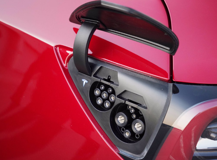
The 2024+ Model 3 charge port door is motorized and opens vertically. The charge port ECU is located in a separate enclosure from the charge port inlet. The charge port ECU has vehicle communication with external charge equipment such as Supercharger, Wall Connector, and Universal Mobile Connector (UMC). The charge port ECU is connected to the High Voltage System (HVS) Controller Area Network (CAN) bus. This means it can communicate with Battery Management System (BMS), Power Conversion System (PCS), and High Voltage Processor (HVP). The High Voltage (HV) charge port harness connects to the Ancillary Bay where power is distributed to the PCS for alternating current (AC) charging and HV battery using fast charge contactors for direct current (DC) charging. The high voltage busbar for DC charging is bolted on the back side of charge port and protected by a plastic cover that can be plugged in to avoid high voltage exposure. For Guobiao type charge port in China market, the AC harness is separated from DC busbar and attached to charge port through a 'W' type rapid connector.
Charge Port Assemblylink
 |
|---|
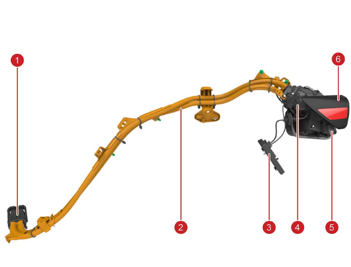
| 1. Lever assisted charge port harness Ancillary Bay connector 2. High voltage charge port harness 3. Charge port ECU 4. Charge port door motor 5. Charge port assembly with door 6. Charge port latch |
| Charge Port Assembly System, Overview |
On single-phase charge ports, the HV busbar is routed to PCS directly for AC charging (up to 48A or 32A limited by PCS). On three-phase charge ports, HV busbar and AC harness are separated for DC and AC charging. The DC busbar is bolted on at both charging port and Ancillary Bay end. A charge port high voltage interlock loop (HVIL or CPIL) exists at connection interface for busbar on Ancillary Bay side to make sure that the HV harness connects properly to the Ancillary Bay while charging. The CPIL does not prevent driving nor HV battery power switch closing if in the open position. The plastic guides along the harness mount to the chassis to make sure there is consistent wire routing. The charge port ECU mounts to the wheel arch area with two plastic hooks and a nut.
 |
|---|
 |
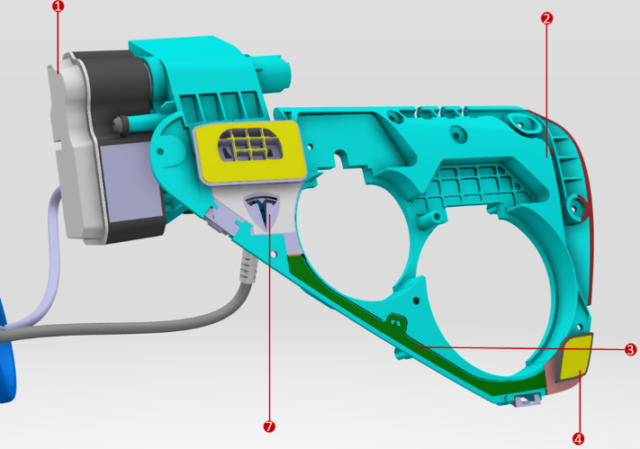
| 1. Door motor (including gears) 2. Charge port trim 3. Trim PCB with hall effect sensor and LED circuit 4. Hall effect location door existence detection 5. Latch stick of AC inlet 6. Chassis ground terminal 7. LED-lit Tesla logo (for charge status indication) 8. Charge port latch motor 9. Latch stick of DC inlet |
| Charge Port Perspective View |
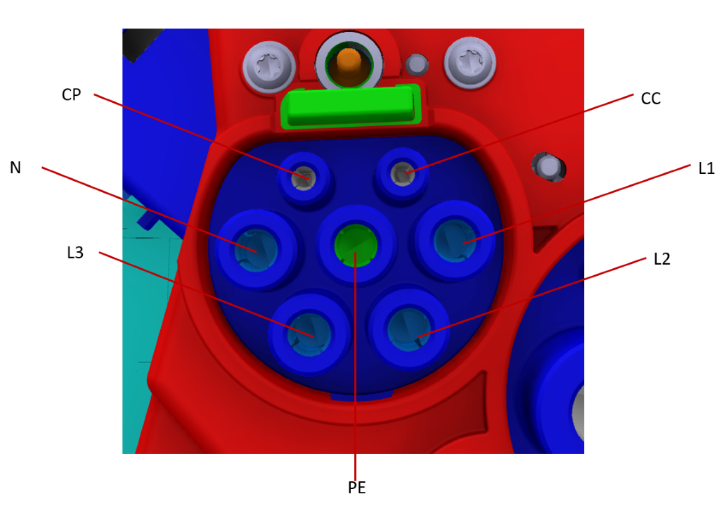 |
| 1. L1/L2/L3: AC Current 2. N: Neutral 3. PE: Grounding 4. CC: Charging Confirm (Proximity) 5. CP: Charging Pilot |
| GB Charger Connector Layout (AC) |
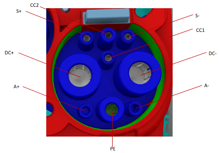 |
| 1. DC+: Direct Current Positive 2. DC-: Direct Current Negative 3. PE: Grounding 4. S+: Charging Communication CAN_H 5. S-: Charging Communication CAN_L 6. CC1: Charging Connection Confirmation 7. CC2: Charging Connection Confirmation 8. A+: Low Voltage Auxiliary Power Supply Positive 9. A-: Low Voltage Auxiliary Power Supply Negative |
| GB Charger Connector Layout (DC) |
The LEDs illuminate a Tesla logo on the upper left side of the cosmetic trim piece.
The flash speed pattern is inversely related to the State Of Charge (SOC). When the SOC is closer to 100% SOC, the flashing is slower, and when the vehicle is done charging, the charge port displays constant green. The flash speed is not related to the line current value or the charge limit setting.
The charge port LED is active when the charge port door is open and one of the following scenarios is true:
- When the vehicle is locked and charging, the green LED stops flashing 2 minutes after vehicle lockout.
- When the vehicle is unlocked and charging, the LED is illuminated during the entire charging session.
- Once the vehicle is fully charged, the charge port LED switches to solid green.
If there is no pilot signal, the LEDs turn off (for example, unplugging a UMC from the wall while connected to vehicle). Each LED color represents a separate condition that must be met as described in the table below:
| LED Color | Charge Port State | Set Conditions |
|---|---|---|
| Solid White | Charging cable can be removed or inserted | The charge port latch is disengaged. |
| Solid Amber | Cable is inserted, but not properly latched | The cable is connected, charge port latch is not engaged, vehicle is trying to engage latch, and vehicle is not charging. |
| Solid Red | Either the charger, charge port, or Electric Vehicle Supply Equipment (EVSE) is not operating as expected | One of the following:
|
| Flashing Green | Charging at expected current | Cable is connected, charge port latch is engaged, and vehicle is actively charging. |
| Flashing Amber | Charging at reduced current | Cable is connected, charge port latch is disengaged, and vehicle is actively charging. |
| Solid Green | Charging is complete | Cable is connected and vehicle is no longer charging. |
| Solid Blue | Pilot is present | Cable is connected and either a pilot signal or fast charger is present. |
For 2024+ Model 3, the charge port door trim PCB no longer features the Ultra High Frequency (UHF) antenna which has been moved to the rear Bluetooth Low Energy (BLE) endpoint instead. The BLE endpoint also hosts the UHF transceiver. Once it detects Radio Frequency (RF) signals from a Tesla charge handle, it sends the request to the security module in Vehicle Controller Left, which then forwards the charge port door request to open via CAN to the charge port ECU. Charge port door position and presence are detected via two separate sensors:
- one mounted next to the door hinge to sense door opening positions via a potentiometer
- one mounted in the cosmetic trim piece to sense whether the door is present when closed via a hall effect sensor.
The sensor mounted in the cosmetic trim piece is also used to determine whether the user pushes the door to open it. For this, the charge port ECU relies on relative changes to the hall effect sensor reading. Since hall effect sensors measure the strength of a magnetic field, one magnet is in the door.
 |
|---|
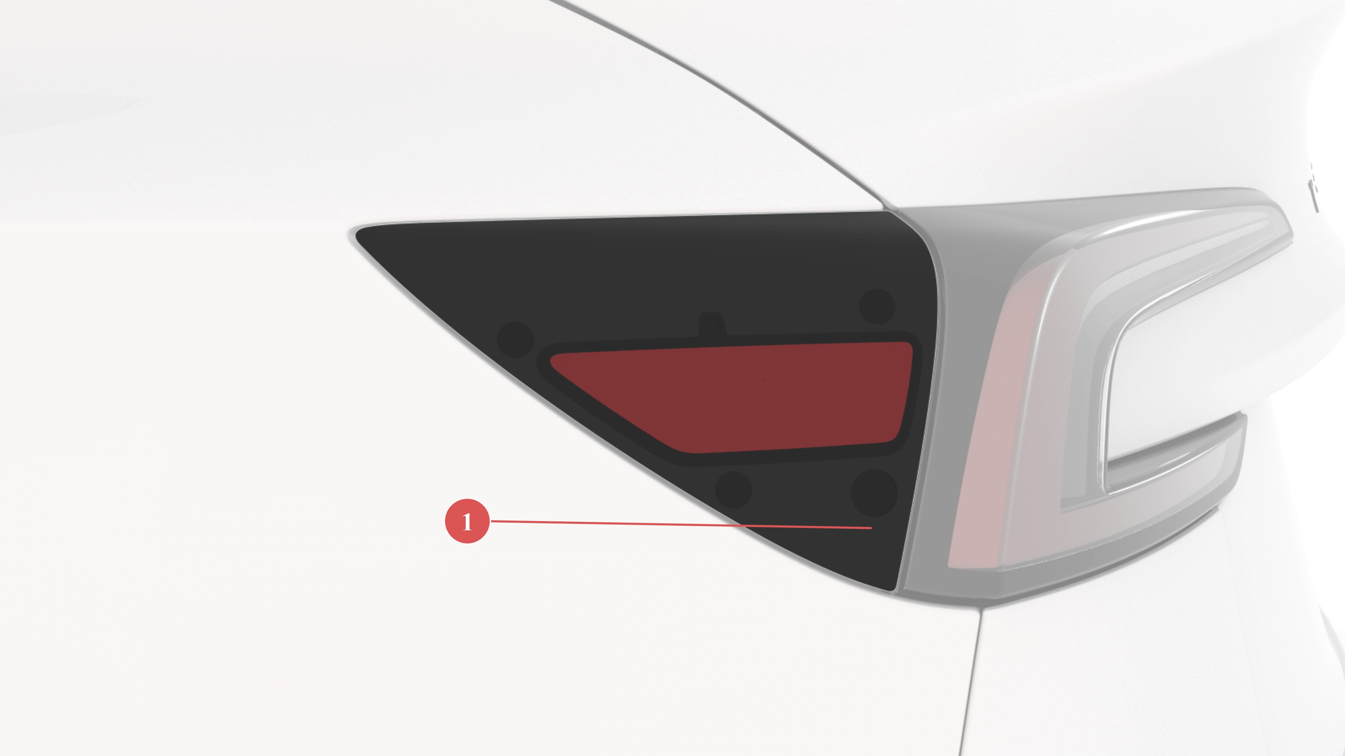
| 1. Magnetic piece |
| Charge Port Door |
Two serviceable Low Voltage (LV) harnesses connect the charge port ECU to the charge port. The harnesses are part of vehicle left body harness. High voltage from the busbar is not exposed below the DC cover of junction point on charge port side. High voltage from the AC charging harness is protected directly based on 'W' type rapid connector design.
 |
|---|
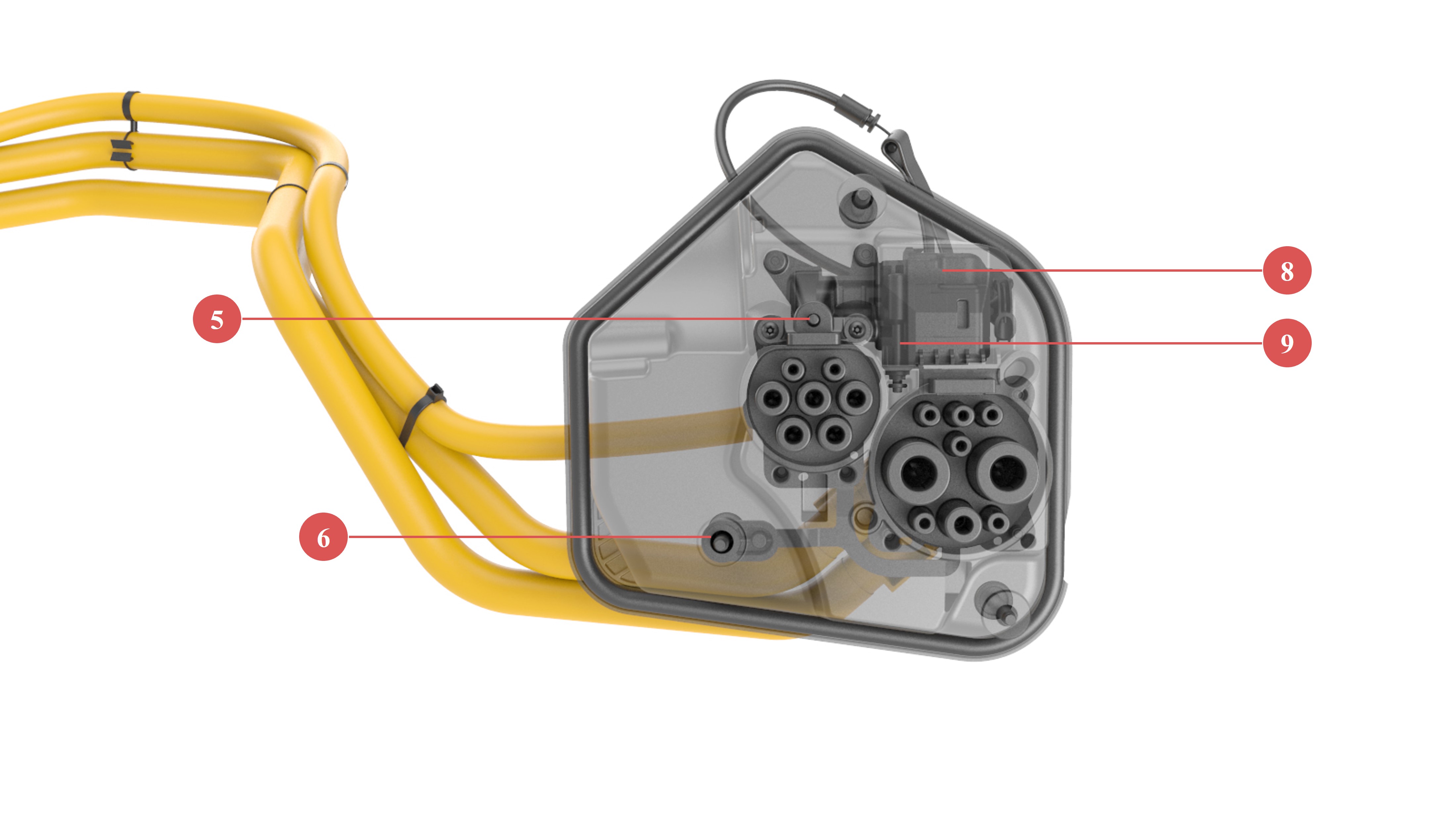
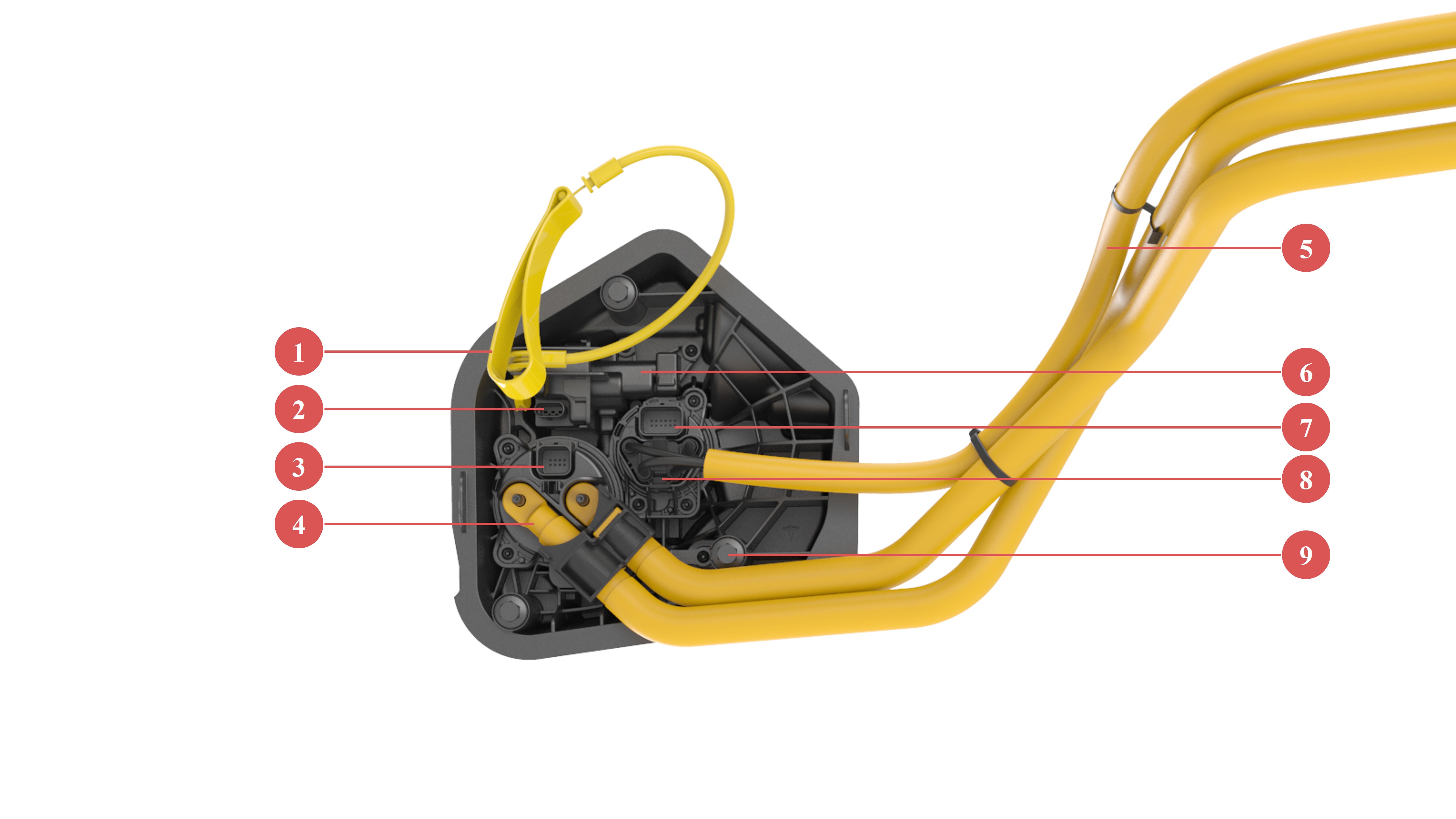
| 1. Charge port latch manual release tab 2. 3 pin latch connector 3. DC inlet signal wire connector (CAN, proximity, ground and thermistor) 4. Bolt connection head of DC busbar 5. High voltage harness for AC charging 6. Latch motor 7. AC inlet signal wire connector (Pilot, proximity, ground and thermistor) 8. 'W' type connector of AC charging harness 9. Chassis ground terminal |
| Back View of GB Charge Port Assembly System |
Four main wiring harness goes through harness inlet, these include plus/minus DC harness, AC harness, and logic signal harness.
Charge Port ECUlink
The charge port ECU controls the following sub-components:
- Charge port door motor
- Charge port door potentiometer
- Charge port latch
- LEDs
- Hall effect door sensor
- Inlet thermistors
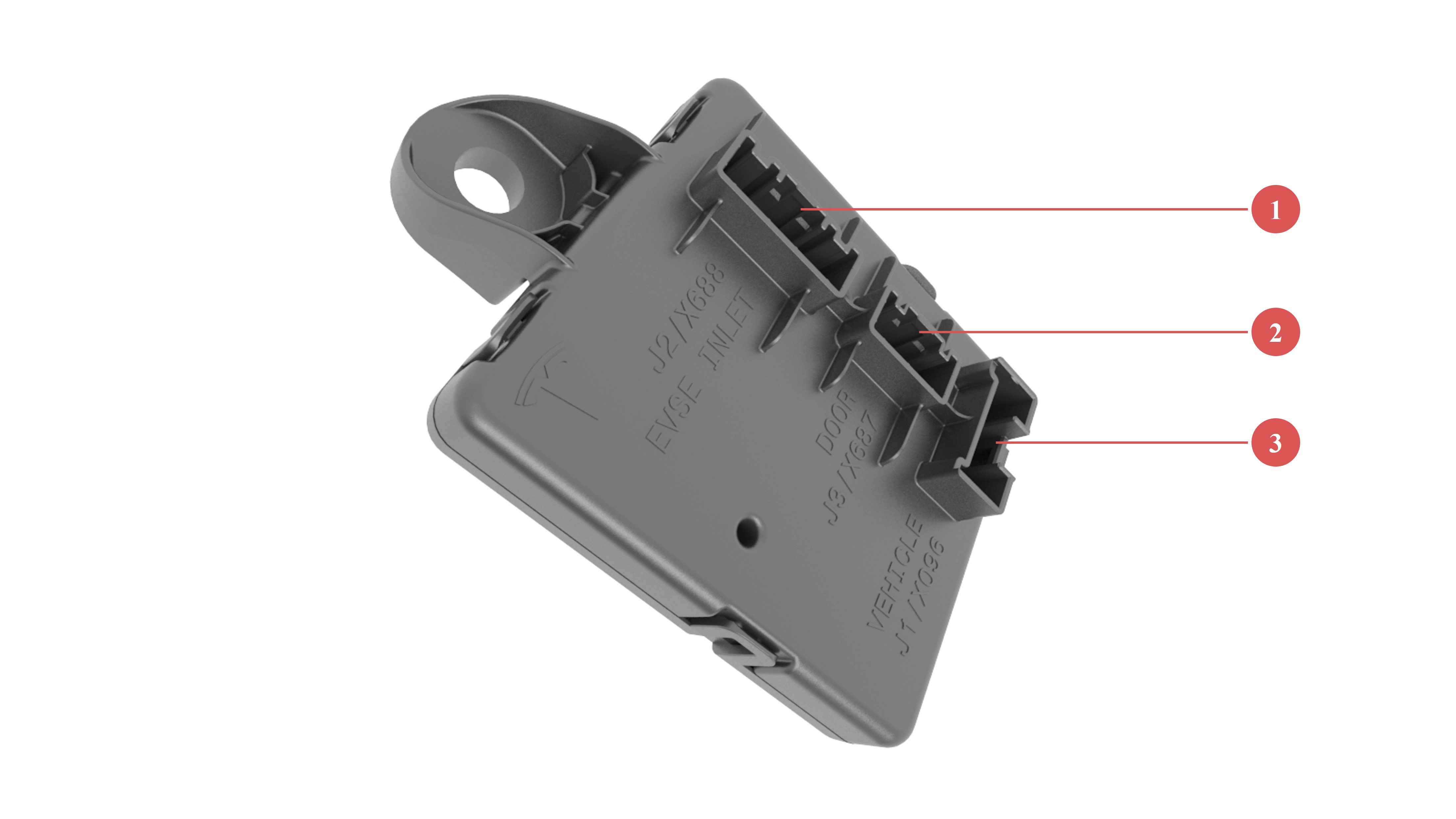
The charge port ECU connects to external charge equipment through pilot, proximity or dual wires CAN (only used in China market) pins in the charge inlet. In AC charging, pilot and AC proximity pins are used, while dual wires CAN and DC proximity pins are used in DC charging. The charge port ECU is not connected to high voltage power. The charge port ECU enclosure is similar across multiple regions, and can house different internal hardware, resulting in different connector pinout. Therefore, in some cases it may be necessary to verify that the charge port ECU unit matches the vehicle it is being installed in.
 |
|---|
| 1. X688 24 pin male connector for inlet LV harness (proximity, Guobiao CAN, pilot, thermistors, latch drive, latch sense) 2. X 687 16 pin male connector for trim LV harness (LEDs, hall effect sensor, door sense, door drive) 3. X096 vehicle interface connector (HVS CAN, power, latch enable signal, Bidirectional hardware fault line) |
| Charge Port ECU |
A 5V source connected to a 330 Ohm resistor supplies the proximity pin. This allows detecting the presence of a charge handle, and the button press state on the handle. For Guobiao charge handles the proximity pin is also used for identifying cable current in AC charging, so the charge port knows the ampere capacity of the connected cable and can adjust max charge rate accordingly.
The pilot pin detects the duty cycle of a 1 kHz PWM signal sent from external charge equipment. The duty cycle indicates the max allowable current draw from the charging station. The positive amplitude of the pilot signal indicates vehicle readiness for charging (see Gen 2 UMC Theory of Operation for more details). In China market, 1 kHz analog communication is the most common way in third-party AC charging. If vehicle is connected to Tesla Wall Connector, the communication method could be in single wire CAN.
Additionally, For Guobiao DC charging, the charge port ECU controls Dual Wire CAN (DWCAN) communication, which means the charge port ECU has the DWCAN relay and transceiver to communicate with external DC charging products. The charge port sends relevant CAN messages from the DWCAN bus to the HVS bus where the BMS, PCS, and HVP are connected.
The charge port ECU connects to the HVP with two hardware lines through connector X096:
- The charge port fault line
- Bidirectional active-low signal used by HVP to disallow charging and door opening.
- It is used to prevent HV exposure when, for instance, the fast-charge contactors are welded or assumed welded.
- The signal can also be set low by the charge port when there are risks of HV exposure.
- The fault line immediately stops charging (via hardware and software) if charging is active.
- The charge port latch enable line
- Unidirectional active high signal used by HVP to allow the charge port to drive the latch into disengaged state for cable insertion.
- Latch driving in engaged direction is not impacted by this hardware line.
Since there is thermal sensing of the charge port inlet power pins, the charge port ECU can read temperatures while charging.
Note
Always consult the circuit diagram and connector reference for the vehicle being diagnosed to confirm which connector is used.
Charge Port Doorlink
The charge port door can be opened five different ways:
- A request by the user interface (UI)
- Pressing the charge port door
- Pressing the button on a Tesla charge handle
- Open with mobile app
- Long-pressing the trunk button on a key fob
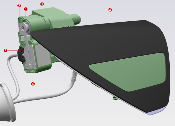
When the charge handle is pressed, a radio frequency signal is sent to rear Bluetooth Low Energy (BLE) UHF antenna. Once BLE detects radio frequency signals, it sends the request signal to security controller, which then forwards the charge port door request to open via CAN to charge port ECU. A potentiometer mounted to the door driveshaft senses the door position. The charge port ECU uses the hall effect sensor to determine door closed/open/press states. Since the hall effect door position sensor is located on the lower right of the charge port door, it is easiest for the hall effect sensor to detect door press when pushing at this location. The charge port ECU measures the door motor current for accurate control during door actuation, and stall current detection when reaching fully closed/open positions.
 |
|---|
| 1. Door Motor Enclosure 2. Potentiometer and Motor PCBA 3. Charge Port Trim 4. Door 5. Door Drive and Sense Harness 6. Door Motor |
| Charge Port with Charge Port Door Motor |
 |
|---|
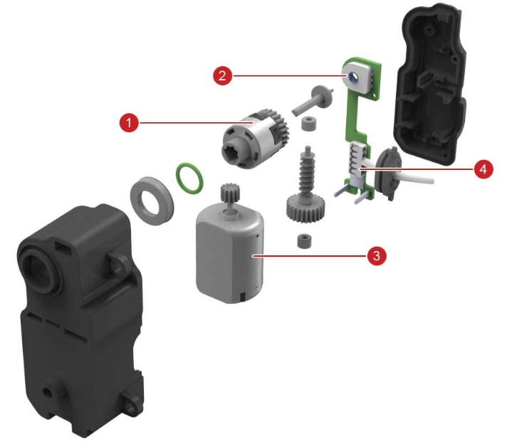
| 1. Door clutch 2. Potentiometer 3. Door motor 4. 5 wire door drive and sense harness |
| Charge Port Door Motor (without Motor Top Housing) |
Charge Port Inlet Latchlink
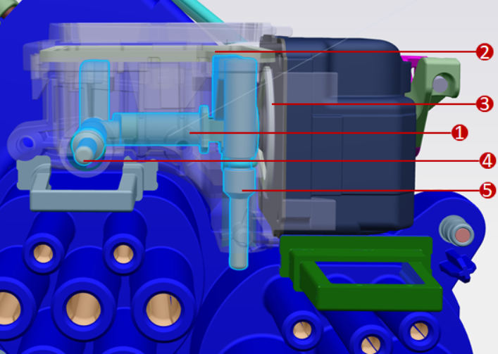
The charge port latch locks the charge handle in place when charging and current is flowing to prevent live disconnect. The charge port latch is actuated by a cam for converting rotational movement into linear movement. The below picture shows an overall view from Latch Actuator going through Release Cable, Latch Actuator, Latch Housing to motivate AC/DC Latch pin, and further from Latch Release Handle if the latch is engaged/disengaged manually.
 |
|---|
| 1. Latch Cam 2. Top Latch Gasket 3. Side Latch Gasket 4. AC Latch Pin 5. DC Latch Pin |
| Inlet Latch Detail with Transparent Latch Housing |
In Guobiao charge port, AC and DC inlet are separated and each inlet has its own latch. But the two latches belong to one mechanical part and are driven by one motor. That means AC and DC inlet latches are driven into engaged or disengaged positions simultaneously.
The latch uses binary position sensing to report engaged or disengaged. There is no continuous position sensing, which means there is no need for calibration either. The latch needs to be driven by the charge port ECU into engaged and disengaged positions. For example, there is no spring to force it into engaged state if latch is not driven. The charge port drives the latch at low voltage in the engaged direction every 2 seconds when the vehicle is in charging state. This is done to confirm that the latch is connected by sensing the latch motor current, since a disconnected latch looks electrically identical to an engaged latch. This can cause a quiet “ticking” noise that is noticeable when listening closely.
Charge Port Latch Manual Release Cablelink
The charge port latch manual release cable is used in emergency situations where the latch or low voltage support is not operating as expected while a charge cable is plugged in. This is the only situation the latch release cable should be used. The latch release cable should never be used to disengage the latch to force insert a charge cable because if the latch does not disengage the inlet could still have power flowing. The latch release handle is accessible by users from the left-hand trunk area. The below picture illustrate the inside latch cam:
Serviceabilitylink
Calibrationslink
The latch does not need calibration. The door potentiometer, the hall effect door closed sensor, and motor stall current measurements should allow the charge port to operate without need of door calibration.
Diagnosis Methodslink
If the charge port does not operate as expected, it is important to determine if another condition prevents the charge port from operating.
For example, the two hardware signals from HVP can prevent the latch from being driven, or the door from opening, for instance in case a fast charge (FC) contactor has welded or is assumed welded. The FC contactor can be assumed welded if the FC contactor logic harness in the HVC is disconnected or damaged. In this case, alerts from HVP will be present, so generally it is a good idea to resolve all HVP alerts prior to resolving charge port issues.
Additionally, as shown in the charge port LED state table, whenever the BMS is in a faulted state the charge port LED will show red LEDs, so any BMS alerts should be diagnosed before suspecting issues with charge port.
The latch does not have a position sensor, only a closed/open binary state signal.
The door potentiometer gives a position value for the door which can be used for diagnosing charge port door issues.
If the hall effect door position sensor is not operating as expected the door may not open when pressing the door, or it may open when not pressing the door. In the former case, the door could be opened by using charge handle or UI. The door will never open when the vehicle is in Drive.
- If the vehicle is in Drive, the door will not open using the UI, charge handle button, or press-to-open.
- If the drive rail is enabled but the vehicle is in Park, and either a UI or charge handle open request is received, the Front Vehicle Controller (VCFRONT) will attempt to disable the drive rail. The drive rail will not be disabled with a push-to-open request.
If the latch fails to engage, the vehicle will not allow DC charging, but will be able to AC charge at up to 16A. This is usually sufficient for emergency charging so that the vehicle can drive to a Service Center. If a handle does not latch when inserted in the charge port, inspect the charge port inlet and handle for any signs of obstruction, try a different handle, or very gently wiggle the handle.
Partslink
These are the only parts that can be replaced:
- HV busbar for DC charging (also for AC in single-phase market)
- HV AC harness for AC charging (only exists in 3-phase market)
- HV busbar back cover
- Charge port door
- Charge port carrier
- Charge port ECU