Second Row - Monopost 6 Seaterlink
Last updated: September 18, 2024
Overviewlink
2021+ Model X has 3 different seating capacities:
-
A standard 5 person seating capacity with a driver and passenger seat in the front row and a three passenger bench seat with backrests that fold flat in the rear. The second row bench seat comes in two pieces, the 60% which is the left and center seating positions and the 40% which is the right seating position.
-
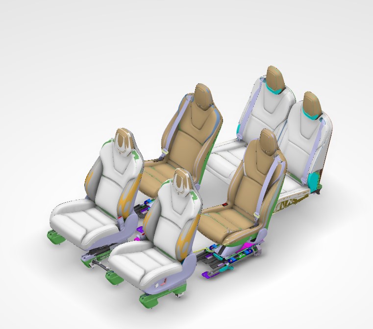
A 6 person seating capacity with a driver and passenger seat in the front row, two independent monopost seats in the second row and two bench type seats in the third row.
-
A 7 person seat capacity with a driver and passenger seat in the front row, a three person passenger bench seat in the second row and a two bench type seats in the third row.
2021+ Model X seats come with 3 different color options, black, white, and cream. The second row and third row seats do not have ventilation, but do have seat heating.
 |
|---|
| Second Row Seats |
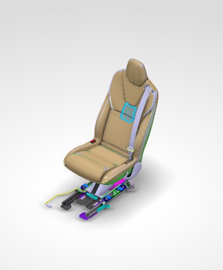
The second row rear seats are a unique minimalist monopost design made to move independent of each other. The monopost sits on a seat track assembly which sits below the floor and is covered by the "magic carpet" so that it remains out of view when the rear doors open.
Coverslink
Component Descriptionlink
2021+ Model X seats are available in cream, white, and, black polyurethane (PUR). This material is a leather alternative. When surfaces of the seat back contact one another, one side is a cloth material, while the other side is PUR. This is to reduce noise issues that are typical when PUR rubs against itself. Along with 3 colorways, there is an option between covers for a long range variant, and covers for a performance variant. The second row seats are perforated on the centermost panels. Performance variant second row seats have also have perforation on the inner bolsters, where the inner bolster meets the outer bolster, there is a piping for added detail and luxury.
Theory of Operationlink
2021+ Model X second row seat covers are secured to the foam with a combination of hog rings and hook-and-loop fastening strips. Then sandwiching the foam, the cover is attached to the upholstery support allowing the seatback to maintain shape prior to attachment to the seat frame. There is also stitch detailing within the seat to help form the shape around the foam.
Serviceabilitylink
Cleaninglink
Cleaning PUR seats with some conventional cleaners (especially alcohol-based) can cause performance and appearance degradation. Do NOT use products containing bleach (sodium hypochlorite). It is therefore important to clean seats with only approved cleaners. Below is a list of approved cleaners:
- Clorox NON Bleach Disinfecting Wipes
- Formula 409
- Seventh Generation NON Bleach Disinfecting Wipes
For CREAM PUR ONLY, isopropyl alcohol is the strongest solvent that can be used without damaging the seat material. Moisten a soft cloth with warm water and isopropyl alcohol and gently wipe the stain in a circular motion.
Warning
Isopropyl alcohol should not be used on Black or White PUR.
Servicing Coverslink
Hog rings must be installed using hog ring pliers to crimp the ring in order to securely fasten the cover to the foam.
Hog rings are a consumable part, as with every removal they need to be cut.
Craftsmanship is extremely important when dealing with and installing covers to ensure that there are no wrinkles or puckers in the material.
Foam/Padlink
Component Descriptionlink
The seat foam, also referred to as the seat pad, provides comfort and stability to occupants.
Serviceabilitylink
If the seat foam and covers have not been installed appropriately it can feel or look as if the seat is missing foam or that the foam has collapsed. Because the foam is sandwiched between the cover and upholstery support, it is possible that it could have been misaligned during installation. In some rare cases, the way in which a customer ingresses or egresses from the vehicle can apply pressure on the outmost edge of the cover and foam, causing the foam to get caught on the upholstery support and not maintain it's full shape. This can be resolved by refitting the cover and foam.
Controllerlink
Component Descriptionlink
Located in the seat back of each of the monopost seats is a Tesla seat controller that controls all electromechanical functions. This includes the seat buckle, occupancy sensors, and heating pad. The 60% controller is the Body Controller Seat 2nd Row Left (BCS2L) and the Body Controller Seat 2nd Row Right (BCS2R).
 |
|---|
| Body Controller Seat 2nd Row |
Theory of Operationlink
The second row seat controllers communicate via Body Bus. These controllers exhibit load ramping. Load ramping is a system behavior where the seat controller loads are not enabled instantaneously. All loads are ramped up to full-on using a gradually increasing duty cycle, starting with a low duty cycle and increasing to 100%. For example, when enabling the seat heaters to maximum heat, the seat controller starts by applying a low duty cycle and slowly ramps up the duty cycle to the requested duty cycle over a few seconds in order to prevent a sudden spike in current draw and strain the low voltage system or exceed the current limitations.
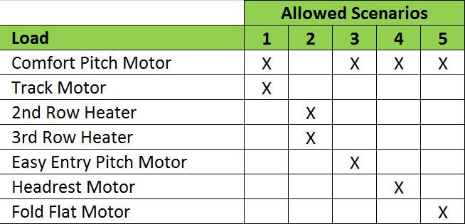
The load balancing restriction is due to the fact that the combined current consumption of all loads exceeds standard fuse ratings. Supporting maximum simultaneous loads across all seats may exceed the maximum power allotted for each seat controller and the power of the vehicle’s DC-DC converter. In Figure 4, the allowed scenarios of loads for each seat controller is shown.
 |
|---|
| Figure 4: Seat controller load restrictions (X = Load activated) |
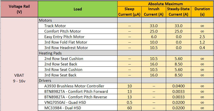
Figure 5 shows the maximum inrush and steady-state current draws for each of the loads on the seat controllers. If all the loads on a seat controller were to be turned on at the same time, the power demand would be too high for the rating of the fuse for each seat controller. By carefully balancing the loads and load ramp up, the seat controller is able to keep its current demand within the power specifications and still efficiently use all seat functions as needed.
 |
|---|
| Figure 5: Seat controller maximum loads |
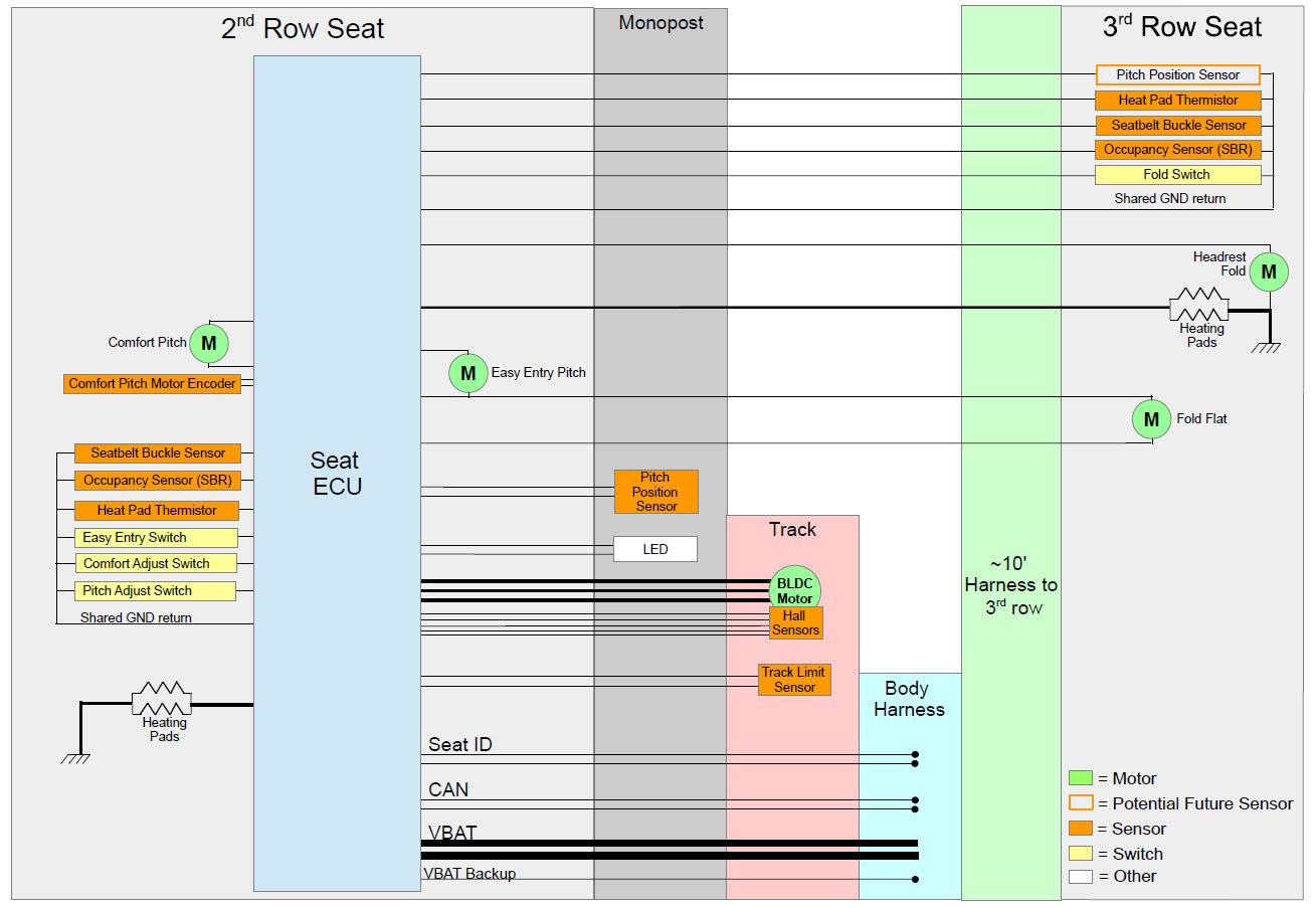 |
|---|
| Rear seats wiring block diagram |
Seat Heatlink
Component Descriptionlink
2021+ Model X second row has heating elements in each of the cushion seating positions as well as the backrests.
The seat heater is made up of the following components:
- High side driver
- Pulse width modulation (PWM)
- Negative temperature coefficient (NTC) thermistors
- Resistive pad
The heating element, or resistive pad, is located only in the center panels of the seat back and seat cushion, the heating element is not located in the side bolsters.
Theory of Operationlink
There are 3 heating temperature targets for the seats (low, medium, and high). Target temperatures for both the cushion and the backrest are:
- Low (Setting 1): 28°C or 82°F
- Medium (Setting 2): 44°C or 111°F
- High (Setting 3): 60°C or 140°F
The seat heaters utilize PWM at 1Hz in order to reach the desired target temperature. This means pulsing the voltage at a controlled frequency. The duty cycle (width of the pulses) will be increased if the temperature read by the NTC is below the target temperature, the duty cycle can be increased all the way up to 100%, providing up to 16V. When the temperature read by the NTC is higher than the target temperature, the duty cycle can be decreased all the way to 0% providing no voltage. Due to this PWM, the voltage at the seat heater is constantly changing and varies due to ambient temperature and heat setting level.
Current travels through the resistive pad generating the heat. This resistance remains constant with a functioning seat heater.
The NTC is located only in the seat cushion, not the seat back. It is connected to 5V through a resistor on the body controller. As the temperature of the seat increases, the resistance on the NTC lowers and the voltage read at the controller goes down. If the thermistor is disconnected, the voltmeter will read 5V or 0V depending on where the disconnect occurs. At around room temperature, the voltage at the NTC should be around 3.6V.
Serviceabilitylink
The seat heater resistive pad is integrated into the seat cover and is therefore not serviceable.
The temperature felt at the surface of the seat, depends on an occupant sitting in the seat. Compressing the foam and trim with an occupant sitting in the seat allows for the occupant to fully feel the temperature provided by the seat. Factors such as a heat soaked interior, body heat from someone sitting in the seat, direct sunlight and ambient air temperatures can play a big role on the temperature readings at the surface of the seat cover.
Occupancy Sensinglink
Component Descriptionlink
Each seat in the second row contains an occupancy sensor, resistive pad, also referred to as the seat belt reminder (SBR). The occupancy sensors are located in the seat cushion. The occupancy sensors are switches distributed throughout the cushion connected in both parallel and series.
Theory of Operationlink
Occupancy sensing for the second row communicates to VCLEFT. The sensor itself is a simple resistive pad that can be tested with a multimeter. Occupied, the resistance should read 1kOhm. Unoccupied, the resistance should read 11kOhm.
The SBRs always actuate for 5th percentile occupants and larger, but may actuate for other smaller occupants or objects below this weight. The second row outboard seat controllers (BCS2R & BCS2L) handle signals from the 2nd and 3rd row SRB and seat belt buckle switches on their respective sides and broadcast the status over Body CAN. The Restraint Control Module uses these signals, together with information from each seat belt buckle, to display an indicator light and sound an audible warning if an occupant has not fastened a seat belt. The SBR status is also used to alert the driver when a seat heater is turned on in an unoccupied seat.
Serviceabilitylink
Occupant sensors distributed throughout the cushion help to prevent situations where small items might trigger the seat belt reminder indicator. At the time of publishing this document, the resistive pad, or seat belt reminder, located in the second row cushion is not a serviceable component. This is due to the infrequency of which this part needs to be replaced as well as current production capability.
Frame and Baselink
Component Descriptionlink
Each seat in the second row is one individual frame. The seat back is not independent of the seat cushion. The motion of the second row seats comes from the base, also referred to as the whale tail.
 |
|---|
| Frame |
 |
|---|
| Whale Tail |
Theory of Operationlink
For monopost seats, the frame sits on top of the whale tail and all pivoting motion comes from the interaction between the whale tail and the frame.
Motorslink
Component Descriptionlink
Monopost seats have 3 motors.
The Fore/Aft track motor is a three phase brushless DC motor located between the 2 tracks of each second row seat under the monopost. This motor is what drives the seat track forward and backward, also known as Comfort Adjust. Located along the tracks is the track position sensor. The track position sensor is a Hall Effect sensor used to detect when the seat track position is at its rear most position and forward most position. The Hall sensor is attached to the moving track and moves along a small metal plate that is attached to the fixed track, and detects when it has gone past the end of the plate.
The pitch comfort adjust motor is located on the lower front section of the seat and is used to control the pitch of the seat.
The pitch latch actuator is used to release the pitch latch during an easy entry position request, to allow the seat to pitch down 20°. This is the only time that the pitch latch actuator is used.
Theory of Operationlink
The motors in the seat allow for the seat to be in various zones.
Comfort Adjust/Pitchlink
The comfort adjust button is located just below the outer shoulder of the seat back. These buttons are 4-way switches that allow movement of the seat in the forward and backward direction. The comfort adjust position can be adjusted up to 100 mm from its rear most position.
- Comfort adjust fore and aft is accomplished using the Track Motor.
- While undergoing comfort fore/aft adjust the controller shall drive the track motor at 3,000 RPM.
- The comfort adjust range is 100mm forward from the most rearward position permitted by the tracks.
- The comfort pitch motor is driven at a frequency of 5 kHz.
- Comfort adjust pitch allows for fine adjustment of the 2nd row seat pitch by ± 3 degrees and requires PWM control.
- The PWM duty of the comfort pitch motor is controlled to not exceed 13 A current draw.
- The comfort pitch motor position is given by an encoder which is active at 5V and inactive at 0V.
- If an obstacle is detected via overcurrent event the motor stops immediately
For the comfort adjust movements the track motor moves at 6000 RPM and the pitch motor moves at 3,000 RPM.
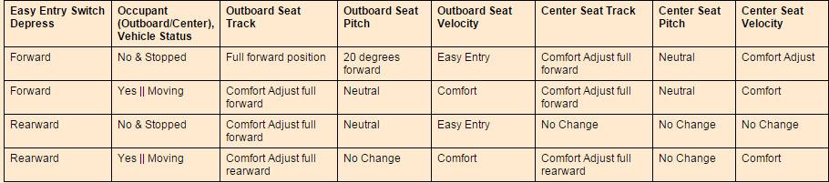
Easy Entrylink
The easy entry position is meant to allow easy entry into the 3rd row seats. The monopost seat will pitch down 20 degrees and move forward 320 mm from the rear most position. In order to allow the seat to fully pitch down, the pitch latch is released by the pitch latch actuator as the seat is pitching down. If an occupant is detected on the seat that is requested to move to easy entry position, the seat will not move.
The easy entry function requires that the seat move to the full forward position and pitch down fully in a short period of time. That means that the seat controller needs to run each of the motors at the highest motor speed possible without exceeding the current limitations. For the comfort adjust function, fast motor movement is not necessary, so the seat controller can use a slower motor speed to accomplish this seat movement. For easy entry the motor moves at the easy entry speed, which is 10,800 RPM for the track motor and 5,000 RPM for the pitch motor. In this speed, the full easy entry position movement takes about 5 seconds to complete. While the seat is in the easy entry range of the seat track, which starts as soon as it leaves the comfort adjustment range in the rear part of the track, the comfort adjustment switches will be disabled. To enable the switches again, the seat must be moved backwards using the easy entry switch.
 |
|---|
Cargo Modelink
A mode that moves the second row seats to the easy entry position (full pitch down and full forward), and folds down the third row seats to allow maximum cargo space in the rear. In this mode the third row headrests are folded 90 degrees down to allow the seats to fold flat forward. This mode can be requested from a button on the touchscreen.
Serviceabilitylink
Second Row Seat Calibrationlink
Each of the second row seats need to be calibrated upon installation or when replacing the seat controller. The calibration is primarily for calibrating pitch latch position for easy entry. This calibration function can be performed via Toolbox in service.
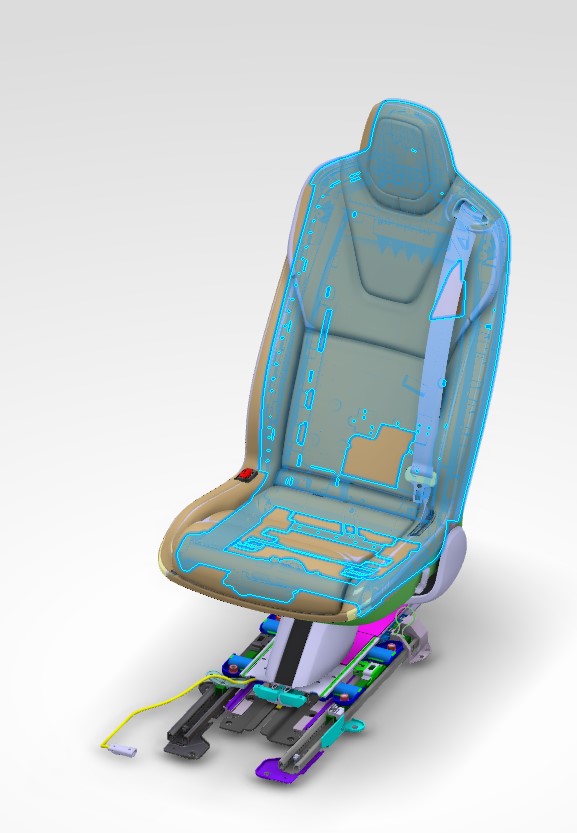
 |
|---|
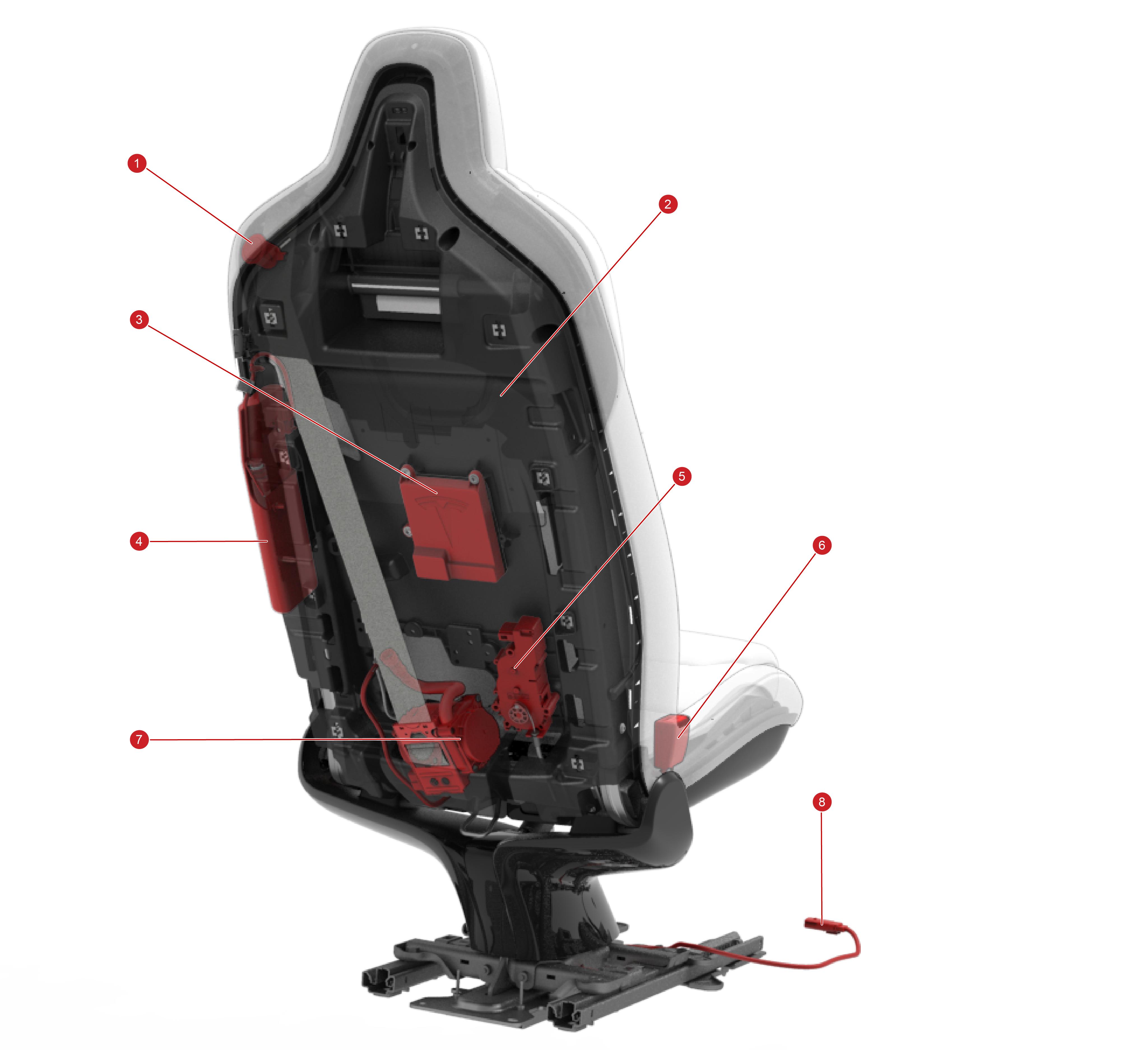
| 1. Easy Entry switch 2. Seat back heater mat 3. Controller 4. Side airbag 5. Pitch latch actuator 6. Buckle sensor 7. Retractor pretensioner 8. Harness to body |
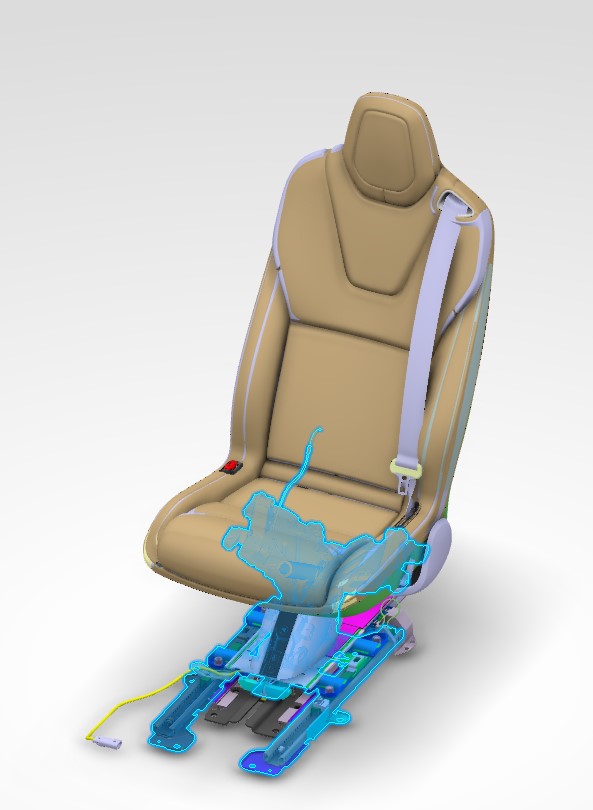
 |
|---|
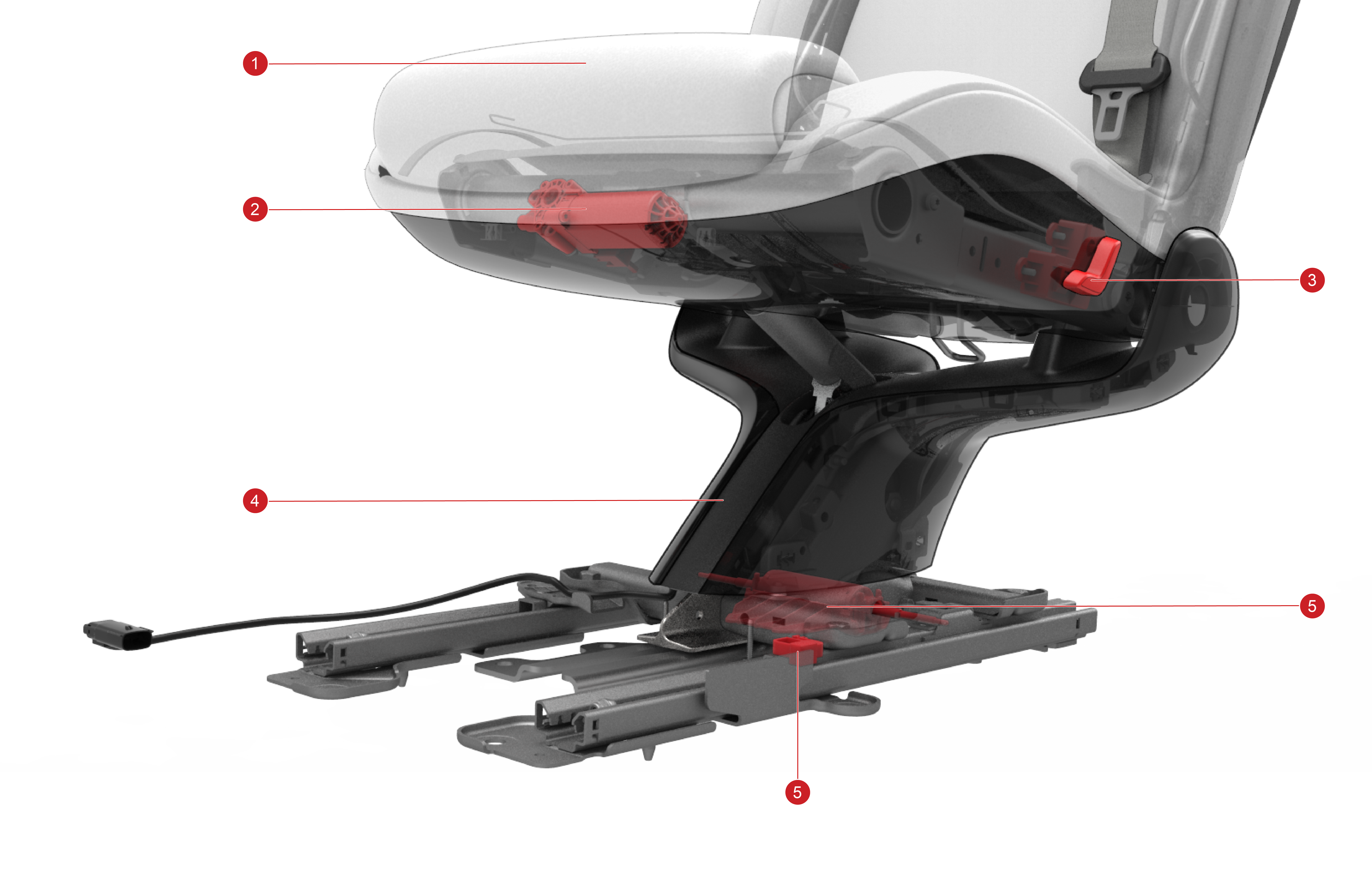
| 1. SBR sensor and seat cushion heater mat 2. Pitch comfort adjustment motor 3. Fore/aft and pitch comfort adjustment switch 4. Monopost (whale tail base) 5. Track position sensor 6. Fore/aft motor (brushless) |
 |
|---|
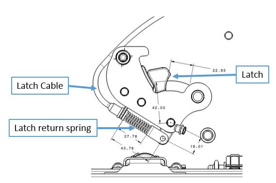
| 1. Latch 2. Latch return spring 3. Latch cable |
The two outboard seats have integrated side airbags, which are controlled by the Restraints Control Module (RCM). The outboard second
row seats each have a single shoulder seat belt pretensioner attached to the lower rear section of the seat. See details in the Theory of Operation.