Shutdown and Recoverylink
Last updated: November 21, 2023
Overviewlink
Cybertruck introduces various new systems to the vehicle architecture that require extra steps to perform and verify a successful vehicle shutdown and recovery. The new systems that affect the shutdown and recovery of Cybertruck are:
- Mid-Voltage (MV) primary bus, which operates at a nominal voltage of 43-48V.
Caution
All electrical buses need to be treated with appropriate caution. However, because Mid Voltage circuits operate at a higher potential than traditional low voltage (9V-16V), they carry an increased risk of component damage, harness damage, or personal injury when misused.
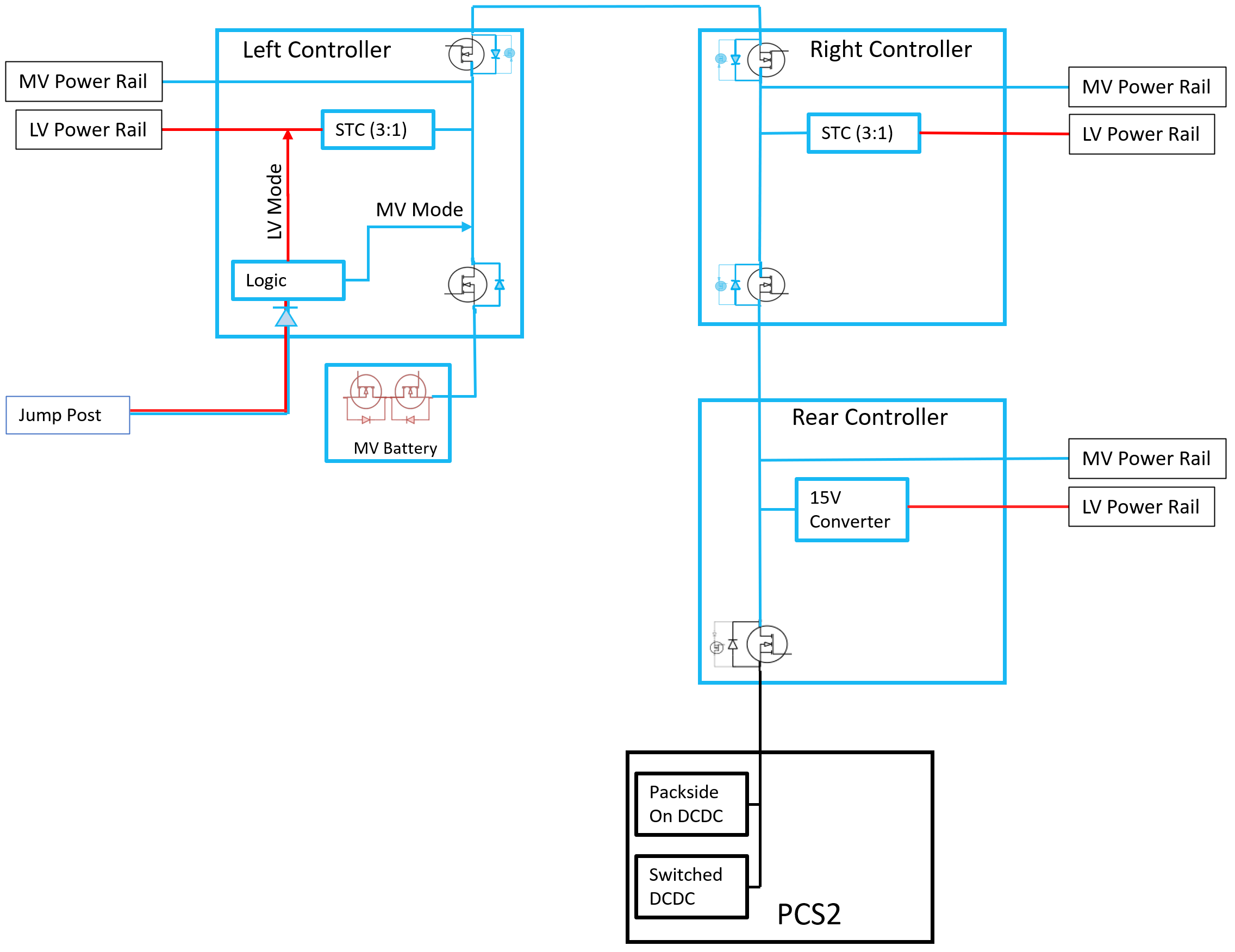
- Two DCDC converters:
- Packside DCDC:
- Permanently connected to the High-Voltage (HV) battery.
- Can provide support to MV bus when pack contactors are open.
- Switched DCDC:
- Connected to the HV battery through HV pack contactors.
- Packside DCDC:
- Steer-by-wire:
- There is no mechanical linkage between steering wheel and steering rack.
- Turning the steering wheel will not move the vehicle’s wheels without power.
Shutdown procedurelink
To fully shutdown the vehicle, disable and disconnect all possible sources of low/mid voltage power sources. There are three (3) internal and two (2) external power sources that are able to support the low/mid voltage system:
-
Internal:
- Mid Voltage Battery
- Packside DCDC
- Switched DCDC
-
External:
- External power source connected to Jump Post
- External power source connected Frunk access cables
The shutdown procedure for Cybertruck when no external power source is connected:
- Open the frunk.
- How – Release via center display or button at front of vehicle.
- Why – This provides access to MV battery and the first responder loop area.
- Lower the Driver and Passenger side windows.
- How – Use the window switches.
- Why – To gain access to the vehicle after powering it down.
- Place the vehicle in service mode by using the touchscreen.
- How – Select Controls > Software, Touch and hold "Cybertruck" for 2 seconds then release. Use the screen keyboard to type "service" into the dialog box and select OK. Select "X" in the upper left corner to exit the 'Service Settings' dialogue box.
- Why – This will put the vehicle in service mode. It also turns off HVAC if it was on.
- Verify vehicle is in Park gear and Transport mode is not engaged.
- How – Verify the UI shows Park gear and that Transport mode is not active.
- Why – If the above conditions are not met, the MV battery self-protection mechanism is prevented from activating when its Electrical Connector Position Assurance (ECPA) is opened. This could result in arcing when disconnecting the battery connector.
- Verify vehicle is not in drive state.
- How – Click the charge port button on UI to exit drive state.
- Why – If the vehicle is being shut down directly from the drive state, there is a risk of a vehicle fault on the next power up.
- Power down vehicle through center display.
- How – Select Controls > Safety. Scroll all the way down and select “Power Off”. Click "Power Off" again in the pop-up window.
- Why – This will cause the vehicle to turn off high load features.
- Remove the rear underhood apron.
- How – It is attached with 7x clips and 3x datums. Pull to unclip.
- Why – To gain access to the MV battery and first responder loop connector.
-
Disconnect the first responder loop connector.
-
How – Disconnect the connector. Slide back the red locking tab. Then, separate the two halves of the connector.
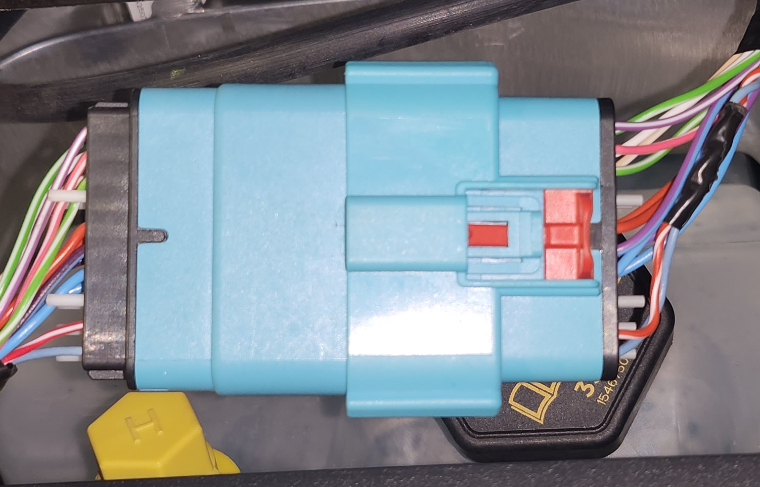
First Responder Loop Connector -
Why – It removes power to the HV pack contactors. It disables switched DCDC directly, and controller logic disables Packside DCDC as power sources.
-
-
Disconnect the MV battery
-
How –
- Release and slide the red locking tab: This opens the MV battery ECPA circuit. The MV battery has a self-protection mechanism (referred to as the ‘MOS’), which can open the circuit between the cells and the battery terminals, interrupting the flow of current to the vehicle. Opening the ECPA triggers the MOS to open and internally disconnects the MV battery from the vehicle.
- Open the swing arm fully. Pull the connector off of the battery.
-
Why – It disconnects the Mid Voltage battery as a power source from the vehicle.
Note
MOS will not open if vehicle is not in Park Gear or Transport Mode is engaged.
-
-
Verify the vehicle has powered down.
- How – Two methods:
- If access to the car computer is available, confirm the lights on the car computer have turned off.
- Press the interior door open button of Front Right (Passenger side) door and verify the latch does not actuate.
- Why – This makes sure that packside DCDC turned OFF and vehicle is safe to work on.
- How – Two methods:
Important
It is recommended to wait at least 60 seconds between Mid-Voltage power cycles. If the vehicle is powered off in Power State DRIVE the Rear controller will keep some of its outputs enabled until 40 seconds after loss of MV power. On boot up, when the Right controller attempts to turn on the Rear controller, the precharge may fail, resulting in the Rear controller not receiving power.
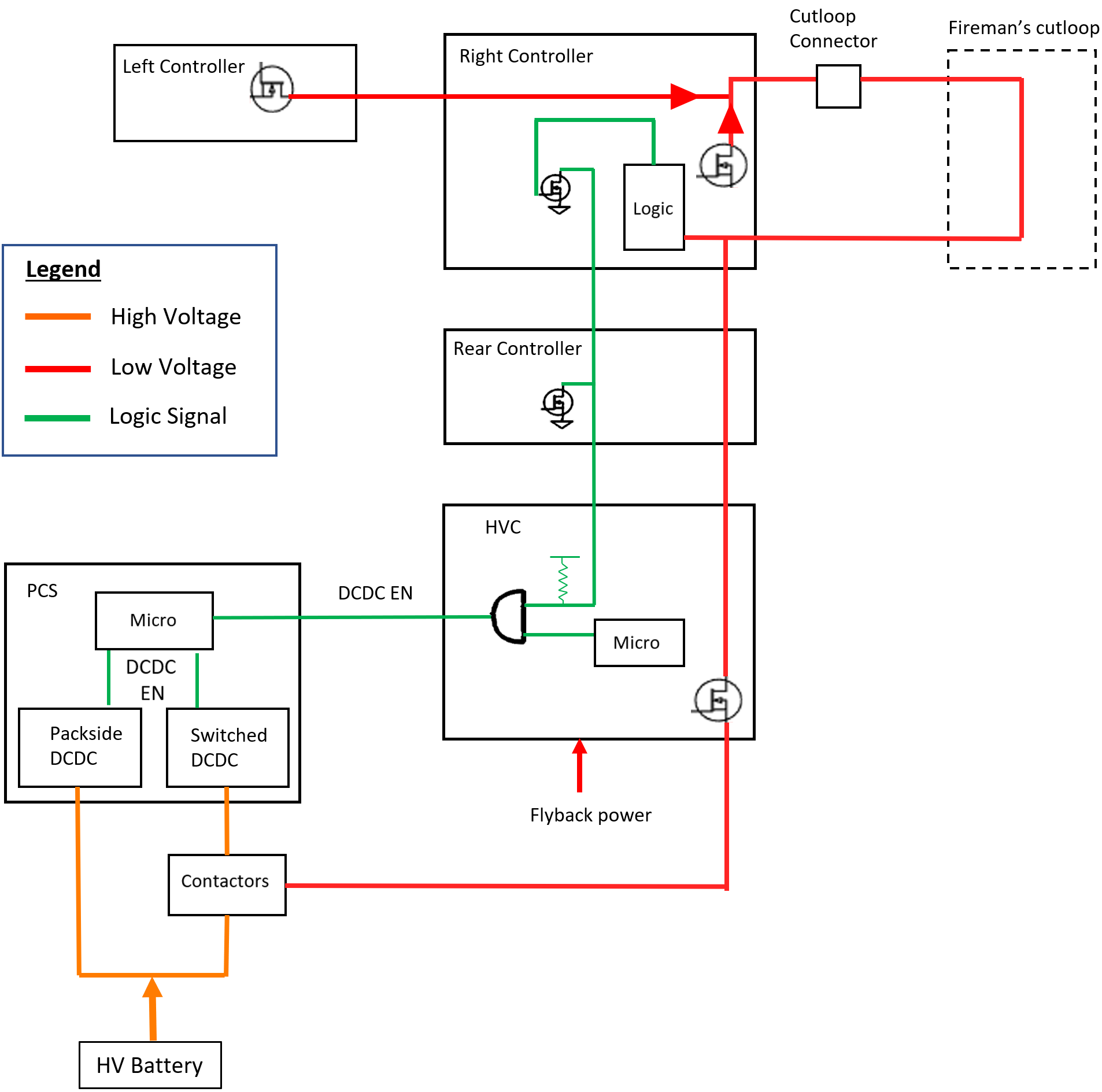
First Responder Looplink
Power wires for the high voltage pack contactors and restraint control module are routed throughout the vehicle into two loops of wire. After a crash event, first responders can cut these wires to disconnect the high voltage battery pack from the vehicle and disable airbags. Since Cybertruck has a packside DCDC that can still support the MV system regardless of high voltage pack contactor status, when the first responder loop is cut/disconnected, the Right Controller pulls the packside DCDC enable line low to disable packside DCDC.
 |
|---|
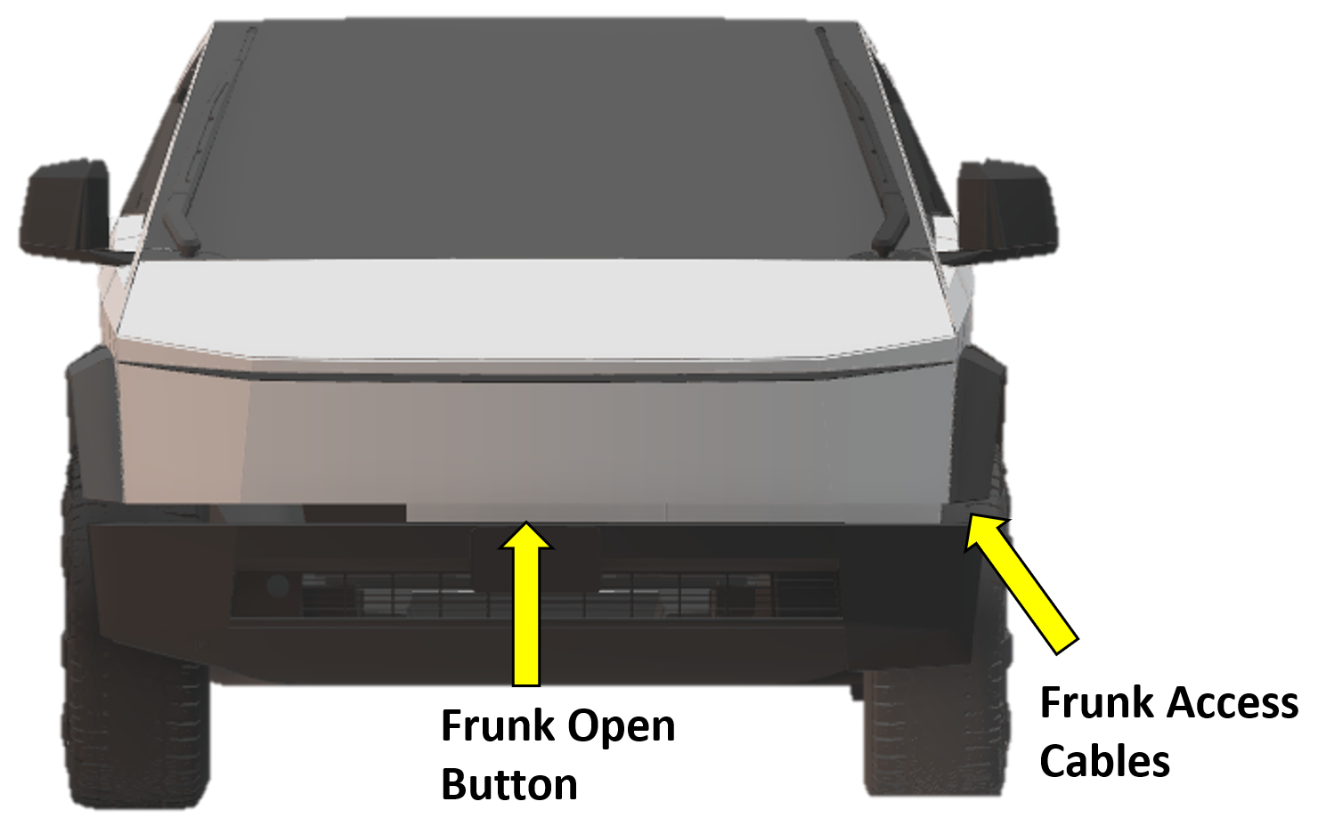
Frunk Access Postlink
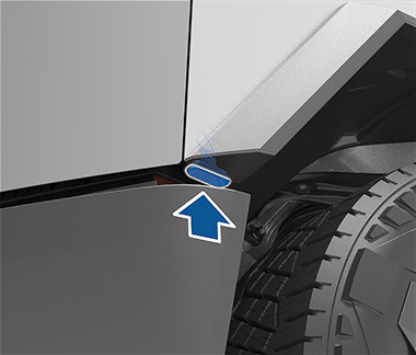
In the unlikely event that Cybertruck has no mid voltage power, users will be unable to open the front trunk (hood) using the touchscreen, mobile app, or front trunk button. In such events, the front trunk can be opened using the frunk access post. The frunk access post location on Cybertruck is different from other platforms. The frunk access cables are located at the corner near the front left (driver side) wheel well and front bumper.
 |
|---|
Note
The vehicle will not open the frunk if frunk access is used when the vehicle is already powered ON and is not authenticated to unlock.
To access the frunk when the MV battery is no longer supporting the vehicle:
- Peel and pull the Grommet out.
-
Once the grommet is out, guide the frunk harness wires out with a finger.
-
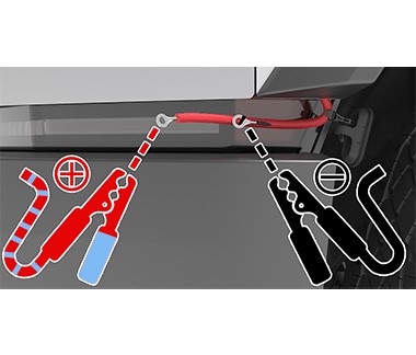
Connect the external power supply to the frunk access cables in this order:
- If possible, turn the external power supply OFF.
- Connect the external power supply leads to frunk access cables.
- Check polarity before connecting.
- Verify set voltage. The following voltage ranges are supported:
- Low Voltage: 9V to 16.5V
- Mid Voltage: 30V to 50V
- If possible, turn external power supply ON.
- The frunk latch should actuate to unlatch the frunk.
-
Try lifting the frunk if the latch is not fully released.
- Wait 10 seconds and press the frunk open button while lifting frunk up.
Note
The 10-second delay is needed to allow the latch positioning to update and the jump pack voltage to stabilize.
- If still does not open,
- Turn OFF external power supply if possible.
- Disconnect the leads.
- Wait 10 seconds.
- Repeat steps 3 to 4.
-
Open the frunk and disconnect the jump pack.
- If possible, turn OFF external power supply.
- Disconnect the leads.
-
Replace the cover.
- Push the frunk access cables into the cavity they were removed from.
- Securely install the cover.
Note
Frunk access post will be inactive in the 16.5V to 30V range.
Note
Standard PP3 9V batteries do not have enough power to open the frunk of a Cybertruck.
Warning
Connecting Mid-Voltage external power supply leads to frunk access cables with power supply powered ON can cause arcing.
Warning
Disconnecting Mid-Voltage external power supply leads to frunk access cables with power supply powered ON can cause arcing.
Jump Postlink
System overviewlink
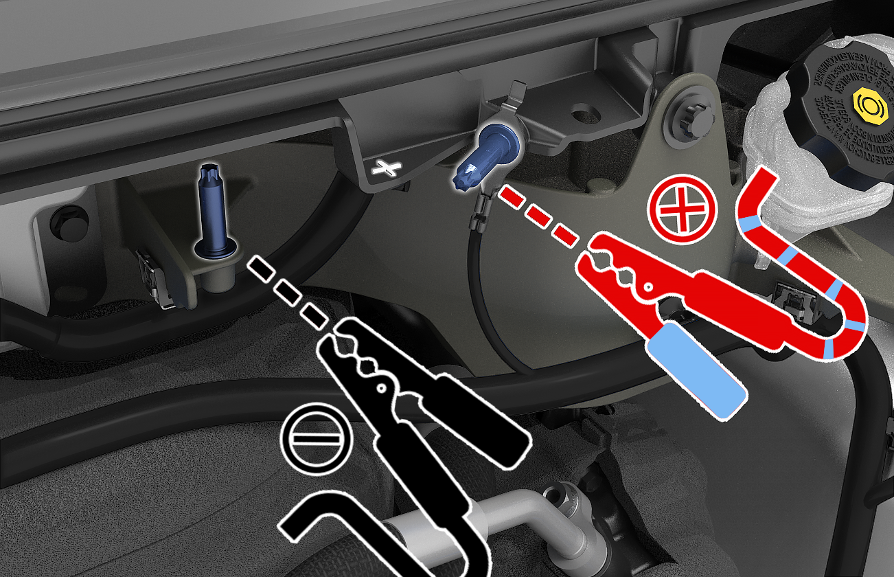
The Cybertruck has a jump post where external power supply can be attached to supply low to mid voltage power to the vehicle in the event that the high voltage system is not able to support the vehicle, or the vehicle has run out of range. The jump post is located underneath the rear underhood apron, centrally, and next to the MV battery. Roadside teams (tow providers) can use this jump post to power certain components of the vehicle, such as:
- Doors: This allows customers to get into the cabin and roadside personnel can access the display.
- Car computer: The center display is used to enable “Transport Mode”, to release the Electronic Parking Brake (EPB), so the vehicle can free roll.
- Steering: The Steer-by-wire system needs to be powered for the truck to be steered.
- Brakes: It provides some assisted braking.
 |
|---|
The jump post is capable of accepting both Low Voltage (LV) and Mid Voltage (MV) as input. The capabilities and intended use of the jump post when using a LV or MV source is different.
Capabilities of each mode:
| Jump Post Mode | Low Voltage | Mid Voltage |
|---|---|---|
| Use Case | Jump-start/ Roadside Recovery | Jump-start/ Roadside Recovery/ Service Work/ Engineering Testing |
| Voltage Range | 12-16.5V (12V) | 30-50V (48V) |
| Jumper cable length | No limit | Maximum 30ft |
| MV Battery Recovery | Unrecoverable | Unrecoverable |
| PCS Recovery | • Attempt Immediately • Periodic retries |
• Attempt Immediately • Periodic retries |
| Supported Functionality High Level |
• Reduced Power Steering • Reduced Power Assist Braking • Parking Brakes • Closures • Doors • Tailgate • Windows • Glovebox • Display and connectivity • Security and authentication • Hazard lighting |
• Reduced Power Steering • Reduced Power Assist Braking • All loads expect the below |
| Unsupported Functionality | • High Level HVAC Blower • Coolant pumps and radiator fans • Autopilot • Suspension • Active cooling and heating elements • Device charging • Auxiliary power |
• HVAC blower at high power • Radiator fans at high power • Auxiliary power |
Note
Jump post will be inactive in the 16.5V to 30V range.
Warning
Jumper cable length when using a mid voltage external power source should be less than 30ft. Using longer cables can cause damage to Cybertruck and the external power source.
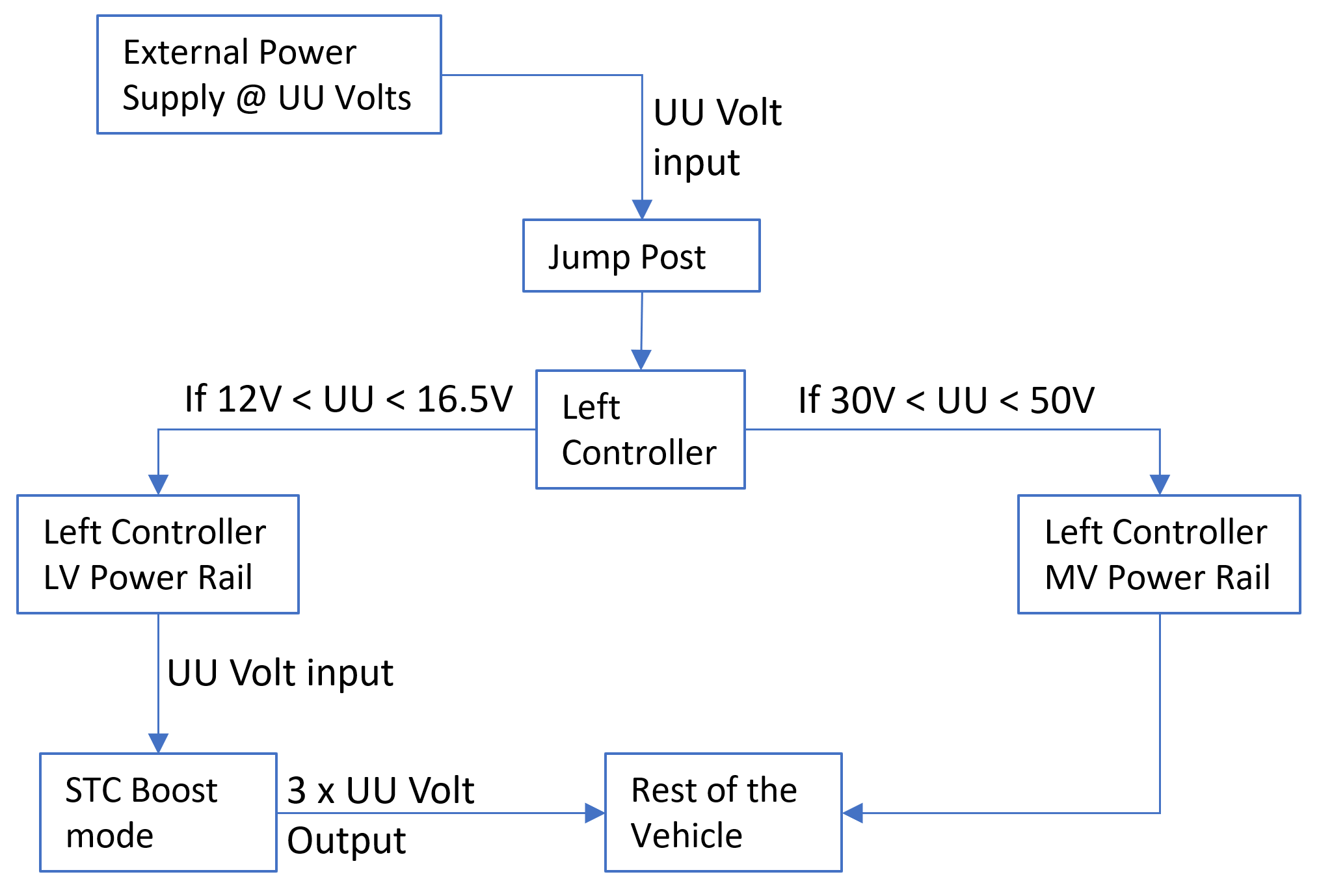
Jump post connects directly to the Left Controller, which has an internal logic check on jump post voltage to decide if the vehicle needs to be in LV or MV jump post mode. This dual voltage support is possible due to the Switched Tank Converter (STC) in Left Controller. STC is a DCDC converter that is able to convert input DC voltage to a higher (boost mode) or lower (buck mode) output voltage in a fixed ratio.
 |
|---|
- If MV voltage input is detected on jump post logic:
- Input voltage is connected directly to MV power rail inside Left Controller.
- Power limits for MV jump post mode are followed.
- If LV voltage input is detected on jump post logic:
- Input voltage is connected to the LV power rail inside Left Controller.
- STC works in boost mode, where it converts voltage with a 1:3 ratio.
- If input voltage is 12V, STC will boost it to 12 x 3 = 36V.
- This boosted voltage is sent to the MV power rail inside Left Controller.
- The rest of the vehicle consumes this boosted voltage.
- Power limits for LV jump post mode are followed.
 |
|---|
Note
Cybertruck cannot provide power output to the jump post; it can only receive power.
Warning
If using a variable power supply, do not transition from LV voltages to MV voltages while the power supply is connected to the vehicle. It can cause extensive damage to the vehicle and external power supplies.
Warning
Do not connect a LV and MV external power supply to the vehicle at the same time; it can cause extensive damage to the system.
Connection Procedurelink
Warning
When using a jump post on a vehicle with inoperative high voltage system, external power supply will be the only power source that will be supporting the vehicle. It is paramount that the connection to the jump is verified to be secure. If the connection is lost at any point, the vehicle will:
- Not have the ability to apply parking brakes.
- Not be able to drive electrically operated closures.
- Not move the vehicle’s wheels when the steering wheel is turned.
How to connect to Cybertruck Jump Post:
- Open the frunk
- If the vehicle still has power, use the UI to open frunk.
- If the vehicle does not have power, use steps listed in the frunk access section.
- Remove rear underhood apron, its attached via 7x clips, and 3x datums. Pull to unclip.
- Verify external power supply is powered OFF if possible.
- Verify the polarity before connecting.
- Connect leads to the jump post.
 |
|---|
Warning
Jumper cable length when using a mid voltage external power source should be less than 30ft. Using longer cables can cause damage to the Cybertruck and the external power source.
Warning
Avoid short circuits when jump-starting the Cybertruck. Connecting cables to the wrong jump post, touching leads together, etc., can damage the Cybertruck and the external power source.
Important
Make sure connections to the jump post are secure, position the external power source stably, and route wires to prevent any potential snags.
- Verify the voltage setting on jump pack/power supply.
- The recommended external MV support voltage is 43V.
- Turn the jump pack/ power supply ON.
- If the HV system is able to support the Cybertruck, or if the task for the jump post was connected is complete, turn the jump pack/power supply OFF.
- Remove the jump post leads.
Warning
When using a MV source, there is high risk for arcing when connecting live connection. Make sure the system is OFF before connecting.
Warning
When using a MV source, there is high risk for arcing when disconnecting live connection. Make sure to power OFF before disconnecting.
Important
It is recommended to not close and latch the front trunk (hood) with an external power supply connected.