High Voltage Distributionlink
Last updated: December 11, 2024
Overviewlink
This document focuses on the distribution of high voltage power among all HV components. Each high voltage component that is not directly used for HV distribution is detailed in other Theory of Operation documents.
The HV distribution architecture is influence by the powertrain configuration of the vehicle. Plaid is the performance-oriented model, and Long Range is the Dual Motor configuration, both part of the Model S (2021+) program.
- All configurations have the high voltage (HV) battery located in the chassis of the vehicle, between the 4 wheels of the car.
-
Long Range configuration has one front drive and one rear drive unit:
- The front drive unit is located on the front subframe, between each front wheel.
- The rear drive unit is located on the rear subframe, between each rear wheel.
-
Plaid (Tri-motor) has one front drive unit and two rear drive units, one for each rear wheel:
- The front drive unit is located on the front subframe, between each front wheel.
- Both rear drive units are located next to each other on the rear subframe, between each rear wheel.
For cabin and powertrain thermal heating / cooling , the HV system uses a heat pump. The HV system does not use a PTC heater (dedicated cabin heater), nor does it use a coolant battery heater. The HV system uses the heat pump to generate heat in the cabin and uses waste heat mode in the drive inverter, along with the heat pump to generate heat for the HV battery. For more details, refer to the section 'High Voltage Battery Thermal Management' in the Non-Structural High Voltage Battery Theory of Operation.
The HV distribution design minimizes complexity, cost, and weight, with most connections consolidated within the HV battery and no separate HV connection components. The HV system includes the following components:
- High voltage battery serves as the primary energy source for the vehicle.
- Drive inverter(s) featuring waste heat mode, which heats the coolant and eliminates the need for a dedicated coolant heater component.
- The Power Conversion System (PCS), located in the HV battery ancillary bay, which supports
- DCDC conversions
- LV to HV conversion for precharging the DC link bus before closing pack-contactors.
- HV to LV conversion once contactors are closed to power the LV bus and manage LV battery state of charge.
- AC to DC conversion for charging vehicle on AC power.
- Cabin heating, ventilation, air conditioning (HVAC) system.
- High Voltage Devices to manage high voltage distribution
- Battery pack contactors manage the energy transfer from the HV battery to the DC link, supplying power to other high voltage components.
- Fast charge contactors used to facilitate direct current charging.
- Pyro disconnects to interrupt the HV loop when necessary
- Shunts to measure current flow
- Charge port assembly and charging harness for charging.
- The High Voltage Junction Box (HVJB), Front Junction Box (FJB), and rapid splitter have been removed, with all HV connections consolidated within the HV battery.
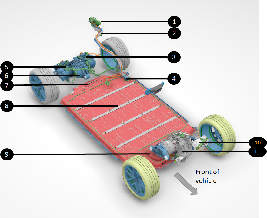
The illustration below provides a general overview of how the HV is distributed from the HV battery to all HV components, which creates the powertrain of the vehicle. The representation shows a Plaid configuration with three drive units .
 |
|---|
 |
| 1. Charge port 2. Charge port busbars 3. Left rear performance drive unit 4. HV battery inlet charge port busbar connector 5. Right rear performance drive unit 6. Rear gearbox 7. HV battery rear service access panel 8. High voltage battery 9. HV battery front ancillary bay 10. Heat pump compressor 11. Front drive unit |
| HV Distribution Overview (Plaid Configuration) |
Most of the HV connections and branching are located inside the ancillary bay of the HV battery.
Location of High Voltage Componentslink
Location of High Voltage Batterylink
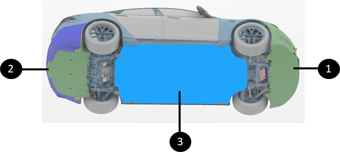
The HV battery is located between the rear and front subframes of the vehicle. The high voltage battery is mounted to the chassis of the vehicle, from underneath. This gives easy access to removal and installation from the bottom of the vehicle and gives the vehicle exceptional performance due to the lower center of gravity.
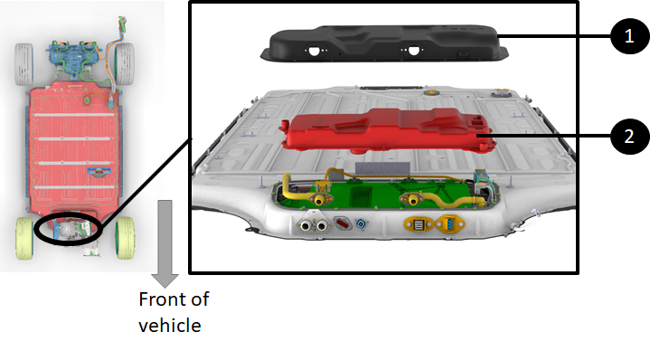
The front ancillary bay of the HV battery, which contains most of the HV devices of the HV battery, is located at the front of the HV battery on top of the modules. For more details, refer to the .
Note
There are no fasteners to be removed from the cabin to drop the HV battery.
 |
|---|
| 1. Front of vehicle 2. Rear of vehicle 3. HV battery |
| Non-Structural HV Battery Location |
Location of Drive Unitslink
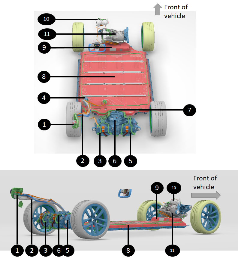
The Model S (2021+) Plaid configuration has three drive units in total. The Long Range configuration has two drive units, and there is no Rear Wheel Drive (RWD) version with a single drive unit.
For Plaidconfigurations, there are two drive units located in the rear subframe between the two rear wheels and one front drive unit located in the front subframe between the two front wheels.
Note
The two rear drive units come as a single assembly in service. The rear and right inverters can be serviced as independent parts, but the drive units come as a single unit with both drive units.
For Long Range/Dual Motor configurations, the rear drive unit is located in the rear subframe between the two rear wheels and the front drive unit is located in the front subframe between the two front wheels.
See the Drive Unit Theory of Operation for more details.
 |
|---|
| 1. Front drive unit 2. Rear right performance drive unit 3. Rear left performance drive unit |
| Drive Unit Locations (Plaid Configuration) |
Location of HV A/C Compressorlink
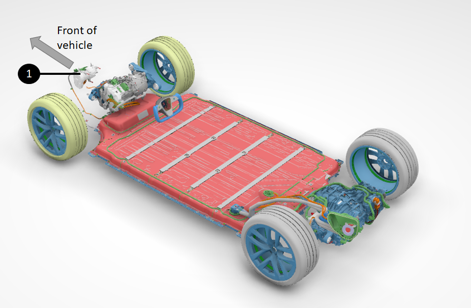
The HV A/C compressor is located between the firewall and the front trunk of the vehicle. The location of the heat pump compressor is behind the firewall for both the structural and non-structural HV battery vehicles. However, the firewall is located in different places in each variant.
 |
|---|
| 1. HV A/C compressor |
| HV A/C Compressor Location |
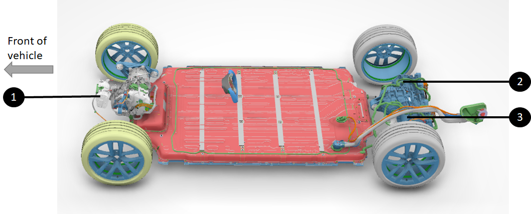
Location of Power Conversion Systemlink
The functions of AC charging and DCDC conversions are handled by the Power Conversion System (PCS). There is no dedicated AC charger or DCDC device in the vehicle.
The PCS (highlighted in red) is located on the front of the ancillary bay of the HV battery. For more details, refer to the Non-Structural High Voltage Battery Theory of Operation.
 |
|---|
| 1. Front ancillary bay access cover 2. PCS directly underneath |
| Location of the PCS |
High Voltage Build Up in the High Voltage Batterylink
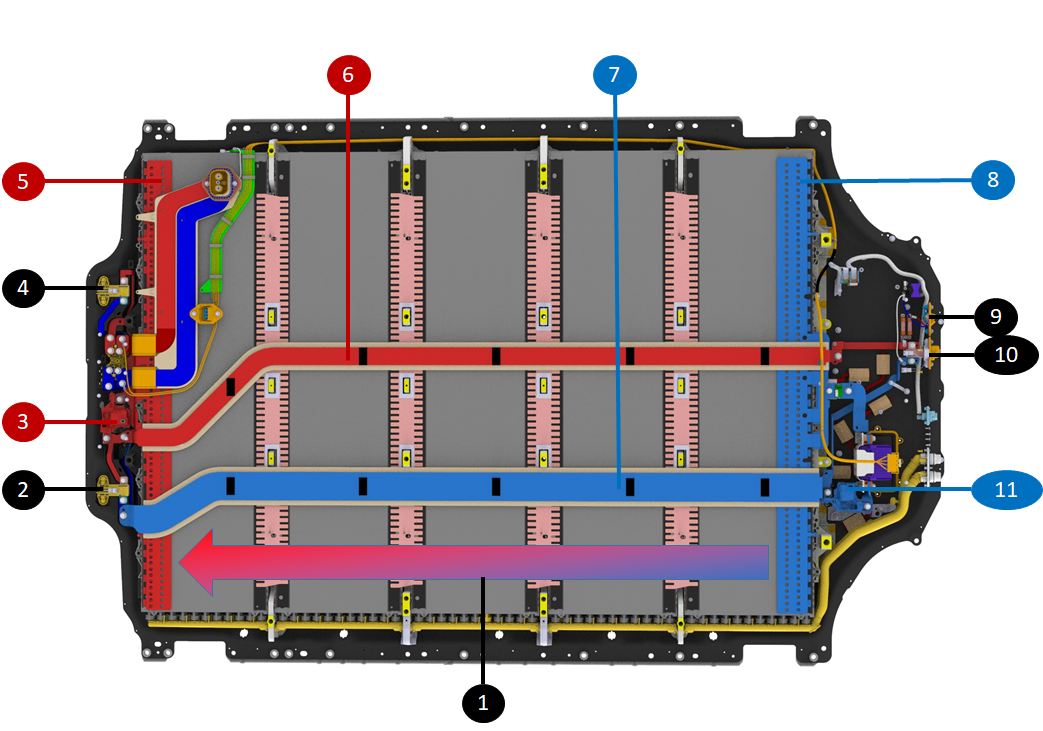
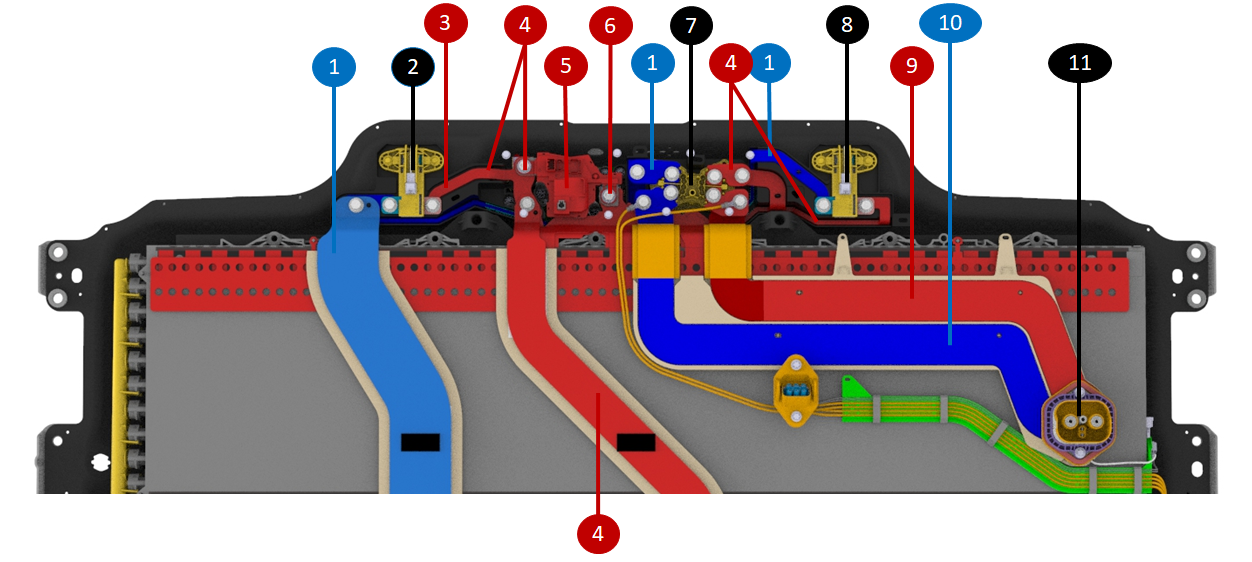
High voltage is generated by building up voltage from each brick of each module. Voltage build up starts at the first brick of module 1 at the front of the HV battery where there is the most negative HV battery terminal.
The full pack voltage is acquired on the last brick of module 5 at the rear of the HV battery where there is the most positive HV battery terminal.
Between the most positive and most negative terminals (rear and front of HV battery), two longitudinal busbars bring the most negative terminal to the rear and most positive to the front.
 |
|---|
| 1. Voltage built up from most negative to most positive terminal via each brick, each module 2. Rear drive unit #1 HV connector 3. Positive contactor 4. Rear drive unit #2 HV connector 5. Most positive terminal 6. Positive busbar bringing DC link positive to the front of the HV battery 7. Negative busbar bringing DC link negative to the rear of the HV battery 8. Most negative terminal 9. Heat pump HV connector 10. Front drive unit HV connector 11. Negative contactor |
| HV Built Up and Distribution in HV Battery |
The longitudinal busbars are after the pack-contactors, meaning that they only have high potential when the contactor on that busbar is closed.
There ends up being switched high voltage, commonly referred to as Direct Current (DC) link, at the front and rear of the HV battery which is convenient to power the rear of the vehicle (one or two drive units) and the front (one drive unit and the heat pump compressor). This is achieved without using external HV cables and having the most negative and most positive HV terminals on the opposite ends of the HV battery reduces risk of HV shorts. For more details, see Non-Structural High Voltage Battery Theory of Operation.
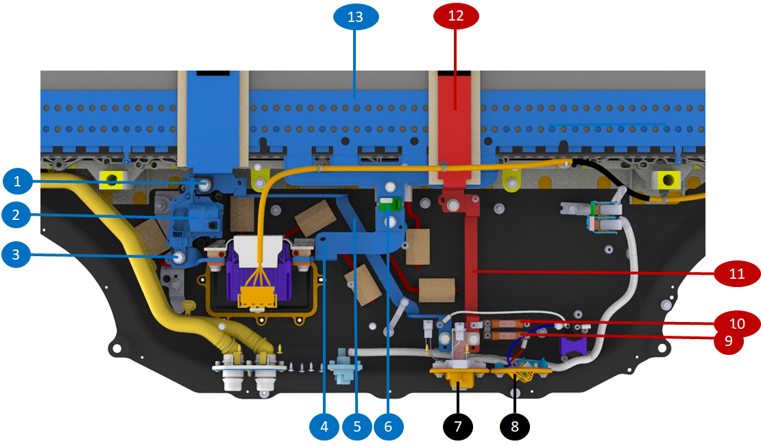
The high voltage at the front of the ancillary bay is directly distributed to the shunt, the pyrotechnic fuse disconnect, and the front rear drive unit. The high voltage at the rear of the HV battery connects to fast charge contactors and rear drive units. The two diagrams below help visualize those connections within the front ancillary bay and the rear of the HV battery.
 |
|---|
| 1. DC link negative (after contactor, only with HV when the contactor is closed) 2. Negative contactor 3. Pack side of negative contactor (HV is present even with the contactor open) 4. Negative busbar from most negative to pyro-disconnect (HV is always present) 5. DC link busbar to front drive unit and compressor HV connectors 6. Shunt on most negative terminal 7. Front drive unit HV connector 8. HV A/C compressor HV connector 9. 63 A fuse for compressor HV feed 10. 63 A fuse for PCS HV feed 11. Only positive DC link busbar in front ancillary bay , to front drive unit HV connector, HV A/C compressor connector via 63A fuse and PCS via 63A fuse 12. Positive DC link coming from rear of HV battery |
| **HV Distribution in Front Ancillary Bay ** |
 |
|---|
| 1. Negative DC link longitudinal busbar brings switched negative to rear of HV battery and distributes DC link negative in the rear (after contactor, only with HV when contactor closed) 2. Rear drive unit HV connector #1 3. Positive DC link busbar to drive unit connector #1 4. Positive DC link busbar (only with HV when contactor closed) 5. Positive contactor 6. Most positive terminal (always hot, has HV even when contactor is open) 7. Fast charge contactors 8. Rear drive unit HV connector #2 9. Positive fast charge busbar (only with HV when positive contactor and fast charge contactor closed)0. Negative fast charge busbar (only with HV when negative contactor and fast charge contactor closed) 11. HV battery inlet charge port busbar connector |
| HV Distribution in Rear of HV Battery |
High Voltage Battery and High Voltage Component Interfaceslink
DC Link to Power Conversion Systemlink
Although the PCS is not used when fast charging, it is connected to the DC link of the HV battery for the following functions:
- Precharging the DC link but to pack voltage before closing contactors.
- Stepping down high voltage from the HV battery to lower voltage to support the low voltage bus of the vehicle.
For more details, see Non-Structural High Voltage Battery Theory of Operation.
The DC side of the PCS DC is connected as follows to the HV battery DC link:
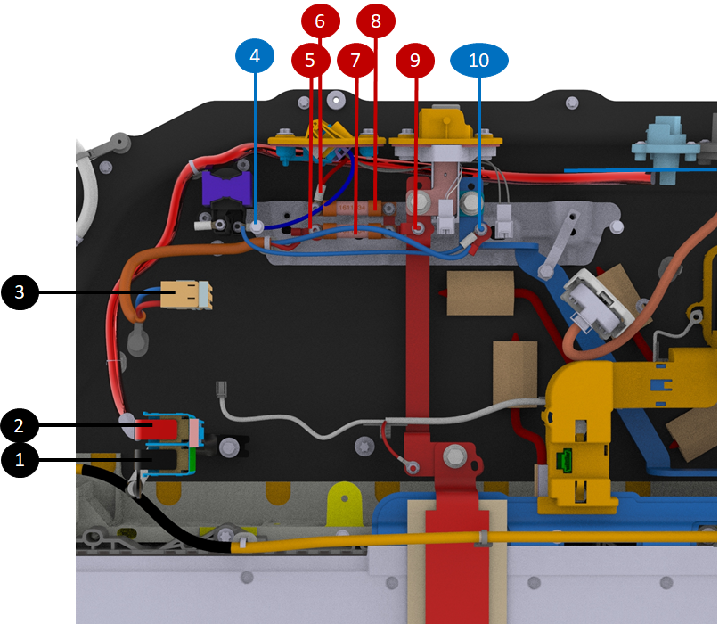
The HV positive terminal of the PCS is connected to the positive DC link busbar, which is supplied by the positive pack-contactor. A 63A fuse is installed between the PCS HV connection and the busbar to provide overcurrent protection. The PCS HV negative connection is made via a cable that is bolted to the main DC link negative busbar using a round terminal, which in turn connects to the negative pack-contactor. The negative link from the DC link to the PCS is not fused, unlike the positive link.
 |
|---|
| 1. DCDC 12V negative (directly bolted down to enclosure) 2. DCDC 12V positive (route to single pole connector at front of HV battery) 3. HV connector to PCS (connect DC link to PCS) 4. DC negative cable to/from HV A/C compressor connector 5. DC link positive to PCS 6. DC positive to HV A/C compressor connector 7. 63A fuse on PCS DC link positive 8. 63A fuse on HV A/C compressor DC link positive 9. DC link positive tap for HV A/C compressor, PCS, and Electromagnetic Interference (EMI) filter 10. DC link negative tap for HV A/C compressor, PCS and EMI filter |
| Connection of PCS to DC Link HV |
AC Input to Power Conversion Systemlink
The PCS converts AC input from wall power through the charge port to DC voltage when charging the HV battery.
The PCS has a dedicated connection to the HV battery inlet charge port busbar connector for this. The HV battery accommodates both single-phase and three-phase charging without hardware differences, using a 6-pole AC connector with 4 pins for Europe, Middle East, and Africa (EMEA) and Asia-Pacific (APAC) markets, and 2 pins for North America (NA) market
Note
The NA HV battery needs a dummy jumper plug on the 6 pin connector to connect the DC busbar to the PCS harness.
- Three-phase markets: AC charging through AC harness and 6P connector with 4 pins populated (L1, L2, L3, N) directly into the PCS harness.
- Single-phase markets: AC charging through DC busbar with 6P "jumper plug" to jump connection AC header pins from DC busbar to PCS harness.
Note
The dedicated AC charge connector was not populated directly at start of production. At start of production and only for NA market, the DC charge inlet had connections directly to the PCS AC inlet.
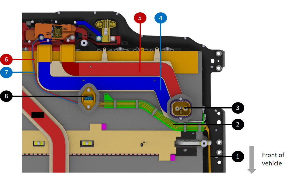
The image below shows the AC connections are at the rear of the battery.
 |
|---|
| 1. Harness bundle taking AC signals from the rear of the HV battery to PCS at the front ancillary bay 2. Same harness spread under the HV battery enclosure 3. HV battery inlet charge port busbar connector 4. Single busbar to charge port (negative when DC charging, single-phase when AC charging in NA) 5. Single busbar to charge port (positive when DC charging, single-phase when AC charging in NA) 6 & 7. Charge port to DC link connections for single-phase AC charging in NA (different routing at start of production - straight from DC charge port inlet to PCS) 8. (Not present at start of production) - AC charge connector for three-phase markets - Connected to a jumper dummy plug for single-phase market |
| Connection of PCS to AC Input |
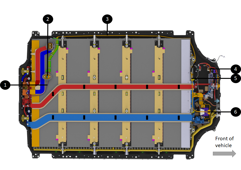
The image below shows an overview at the HV battery level and shows how AC signals travel from rear to front of HV battery to reach the PCS.
 |
|---|
| 1. Charge port to DC link connections for single-phase AC charging in NA (different routing at start of production - straight from DC charge port inlet to PCS) 2. (Not present at start of production) - AC charge connector for three-phase markets - Connected to a jumper dummy plug for single-phase market. 3. Harness bundle taking AC signals from rear of HV battery to PCS at front ancillary bay 4. HV connector to PCS (connect DC link to PCS) 5. Harness bundle taking AC signals from rear of HV battery to PCS at front ancillary bay . PCS AC input connector |
| The Two Styles of Charge Port Inlets |
Charge Port to DC Linklink
Fast Charge (FC), also known as Direct Current (DC) charging, involves the vehicle receiving DC voltage directly into the HV battery without any internal conversion system. The conversion from Alternating Current (AC) to DC occurs outside the vehicle, like in Supercharger or CHAdeMO stations. The HV battery uses FC contactors to connect each side of the DC link to the charge port cables.
The DC Connection to the PCS section describes the charge port busbar route from the HV battery charge port inlet to the FC contactors assembly, which closes during Fast Charge, allowing a direct connection between the HV battery DC link and the HV battery inlet charge port connector.
Front Drive Unit and HV A/C Compressorlink
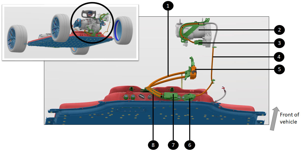
The front drive unit and HV A/C compressor are both located in the front of the vehicle, between the firewall and the front trunk (or frunk).
The HV routing for the front drive unit and HV A/C compressor starts from two of the high voltage connectors at the front ancillary bay of the HV battery. The HV A/C compressor and front drive unit have their dedicated short HV harnesses.
 |
|---|
| 1. Front drive unit HV harness 2. HV A/C compressor 3. HV connector at HV A/C compressor 4. HV A/C compressor HV harness 5. HV connector at front drive unit 6. HV A/C compressor HV connector at front ancillary bay 7. Front drive unit connector at front ancillary bay 8. Bracket guiding front drive unit HV harness |
| Front Drive Unit and HV A/C Compressor HV Connections |
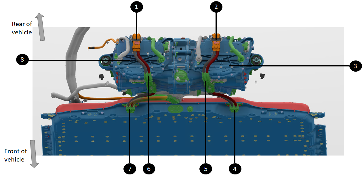
High Voltage Battery to Rear Drive Unitlink
The HV routing for the rear drive units originate from the high voltage connectors located at the rear of the HV battery.
- The Tri-motor configuration has two harnesses going to each drive unit.
- The Long Range configuration has one harness going to the single drive unit.
The same HV battery is used for Long Range and Plaid (Tri-motor) configurations. For the Long Range configuration, a dummy plug is installed on the HV connector of the HV battery intended for the second drive unit of Plaid (Tri-motor) configurations.
 |
|---|
| 1. Left rear drive unit HV connector 2. Right rear drive unit HV connector 3. Right rear drive unit 4. Right HV battery connector to right rear drive unit 5. Bracket holding HV harness to right rear drive unit 6. Bracket holding HV harness to left rear drive unit 7. Left HV battery connector to right rear drive unit 8. Left rear drive unit |
| HV Connections to Rear Drive Unit (Plaid Configuration) |
 |
|---|
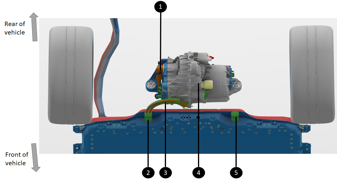
| 1. Single long range drive unit HV connector 2. HV battery HV connector to single long range drive unit 3. Single long range drive unit HV harness and bracket 4. Single long range drive unit 5. Dummy plug sealing spare HV connector and closing high voltage interlock loop (HVIL) (which would connect to second rear drive unit for Plaid configurations) |
| HV Connections Routing to Rear Drive Unit (Long Range Configuration) |
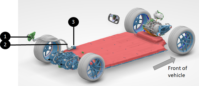
Charge Port Connectionslink
The high voltage routing for the charger port starts from the high voltage connector at the front of the HV battery. From there, refer to the section on Alternating Current (AC) and Direct Current (DC) connection to Power Conversion System (PCS) internally to the HV battery.
 |
|---|
| 1. Charge port 2. Charge port harness to HV battery 3. HV battery inlet charge port busbar connector CP-HV-AT-HVBATT |
| Charge Port HV Connections |